Rack and Pinion Installation: Alignment and Backlash
10 min
- Key Takeaways
- How to Set the Rack and Pinion Mounting Distance
- How to Align the Rack with the Linear Guide
- Check Fit Using CAD Models
- How to Check Two Opposed Racks Driven by One Pinion
- How to Check Tooth Face Overlap and Contact
- How to Measure Rack and Pinion Backlash
- How to Check Full Travel After Tightening
- Common Installation Problems and What to Check
- FAQs About Rack and Pinion Installation
Key Takeaways
- Use the component drawings to set the nominal mounting distance from the rack datum to the pinion axis.
- Check carriage travel with the pinion disengaged, then align the rack to the carriage’s actual direction of travel.
- For two opposed racks, check both mounting distances and verify that both racks mesh at the specified jaw opening.
- Check tooth contact and measure backlash at several points. After tightening, cycle the mechanism slowly through its full stroke without a workpiece.
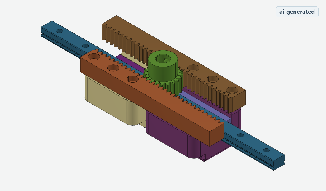
This rack and pinion installation guide uses a manual gripper with two straight racks on a shared linear guide rail. Each rack is attached by a bracket to its own carriage. As the pinion turns, the racks move in opposite directions to open or close the jaws. Once you’ve selected the components, check the rack dimensions in the straight rack drawings before setting the nominal mounting distance. Then verify that the distance stays consistent over the full stroke. The same mounting and alignment checks apply to single-rack mechanisms.
How to Set the Rack and Pinion Mounting Distance
Figure 1 illustrates the nominal geometry of a standard spur pinion with no profile shift and a mating straight rack. The mounting distance is measured perpendicular to the rack back face, from that datum to the pinion axis. On the rack drawing, find the height from the back face to the pitch line. At the nominal position, the pinion axis is one reference pitch radius from the rack pitch line, measured perpendicular to the line. The overall rack height extends to the tooth tips. Use the pitch-line height when locating the pinion axis.
If a shoulder on the bracket locates the rack, show the offset from that shoulder to the rack back-face datum in the assembly section. Account for the offset along the direction of the mounting dimension. Use the specified mounting distance or adjustment if the manufacturer provides one for the mating components. For the nominal geometry of a standard pair, see the rack assembly notes.
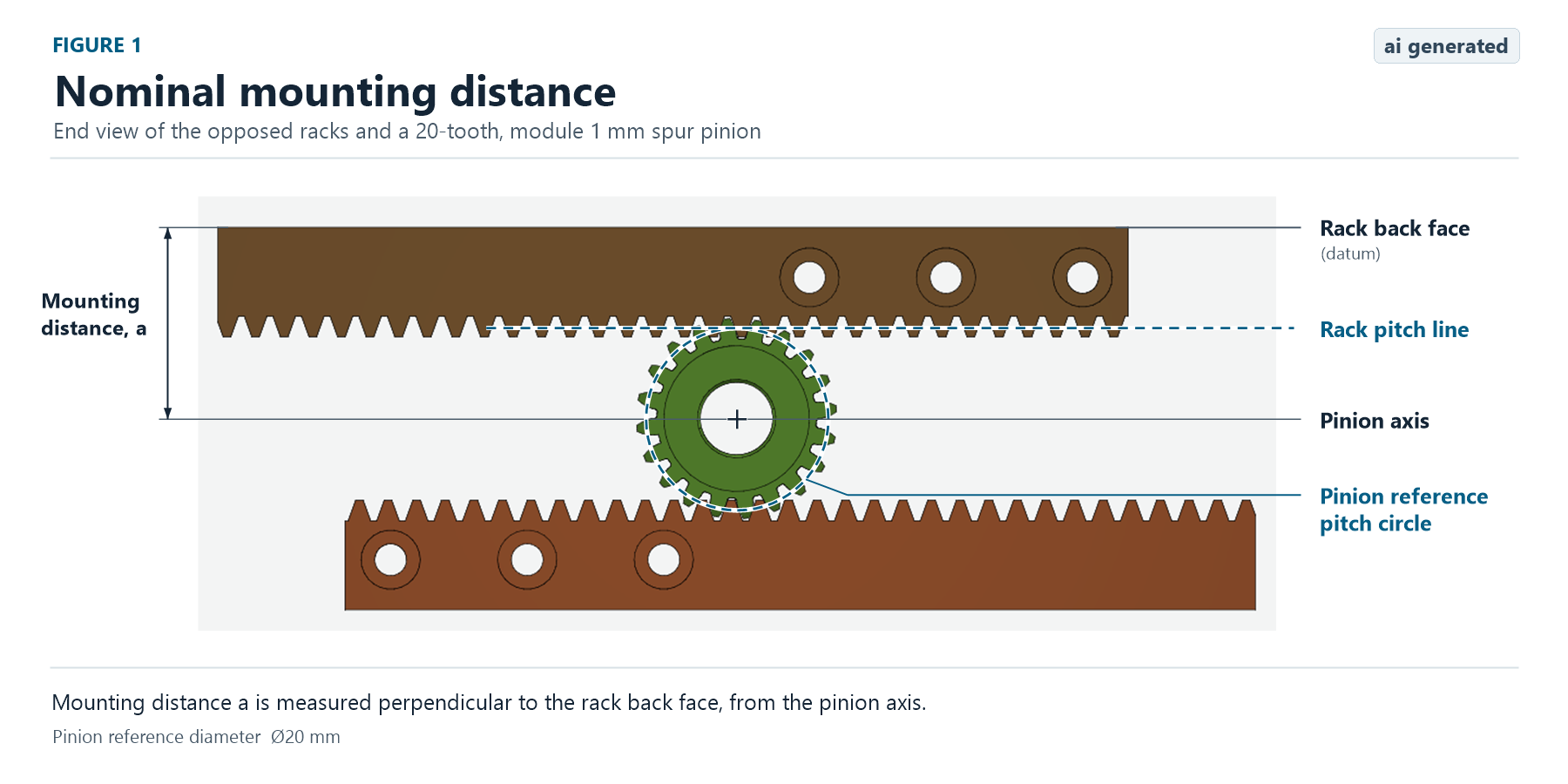
Figure 1. Rack and pinion mounting distance.
How to Align the Rack with the Linear Guide
With the pinion disengaged, slowly move the carriage through its intended stroke. If the carriage binds, check how the rail seats on its mounting surface, whether tightening the fasteners has distorted the rail, and whether a bracket or travel stop is interfering with movement. See the linear guide overview for more on mounting surfaces and rail fasteners.
Once the carriage moves freely, identify a rack datum surface on the drawing that is parallel to the pitch line and has a known offset from it. For a fixed rack, mount the dial indicator on the carriage. For a rack that moves with the carriage, mount the indicator on the frame. Place the indicator tip against the datum surface. Set its measuring direction perpendicular to both rack travel and the pinion axis. Compare readings near both ends and at mid-stroke.
If the rack is skewed in the plane of mesh, the engagement depth changes over the stroke. A mechanism that runs freely at mid-stroke can bind near one end and have excess clearance near the other. If the mounting arrangement allows adjustment, secure the rack temporarily, align it, then tighten to specification and measure again.
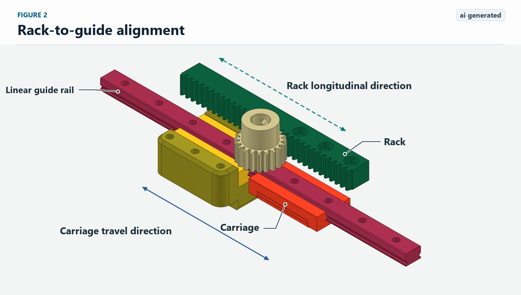
Figure 2. Use the carriage’s actual direction of travel as the reference for rack alignment.
Check Fit Using CAD Models
Check the fit before you drill mounting holes. Follow the CAD download guide to get models for the parts you’ve selected, then check the rack and rail mounting holes and carriage clearance in your assembly.
How to Check Two Opposed Racks Driven by One Pinion
With the racks fixed in their transverse positions, shifting the pinion axis toward one rack reduces the mounting distance on that side and increases it on the other. If one side feels tight and the other loose, check both mounting distances. Then verify the pinion axis and each rack location against their assembly datums.
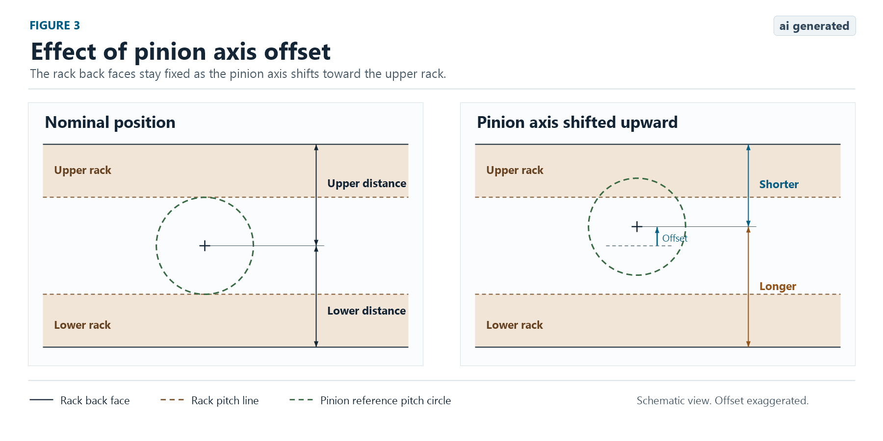
Figure 3. Both racks stay in place. The exaggerated pinion offset shows how the two mounting distances change.
-
Check one side at a time. If the design allows it, engage only one rack. Run it through its working stroke and note any tight spots. Repeat on the other side.
-
Set both jaws to the specified opening. Position the two carriages and jaws as shown on the assembly drawing. Check the longitudinal position of each rack relative to its bracket. At the specified opening, verify that both racks can mesh at the same pinion angle. If you have to move one jaw to engage its rack, check that rack’s position along the direction of travel.
-
Run both racks together at low speed. From the reference opening, move the jaws slowly in both directions. Check that both racks stay in mesh throughout the working stroke and note which side reaches its stop first. If the mechanism binds with both racks engaged, stop and record the position for the full-travel check.
How to Check Tooth Face Overlap and Contact
In an orthographic view looking along the rack travel direction, compare the axial span of the pinion teeth with that of each rack. The shared span is the geometric tooth face overlap for that side. The v9 CAD model in Figure 4 shows 10 mm on each side at the position illustrated. Check the actual contact pattern during trial assembly.
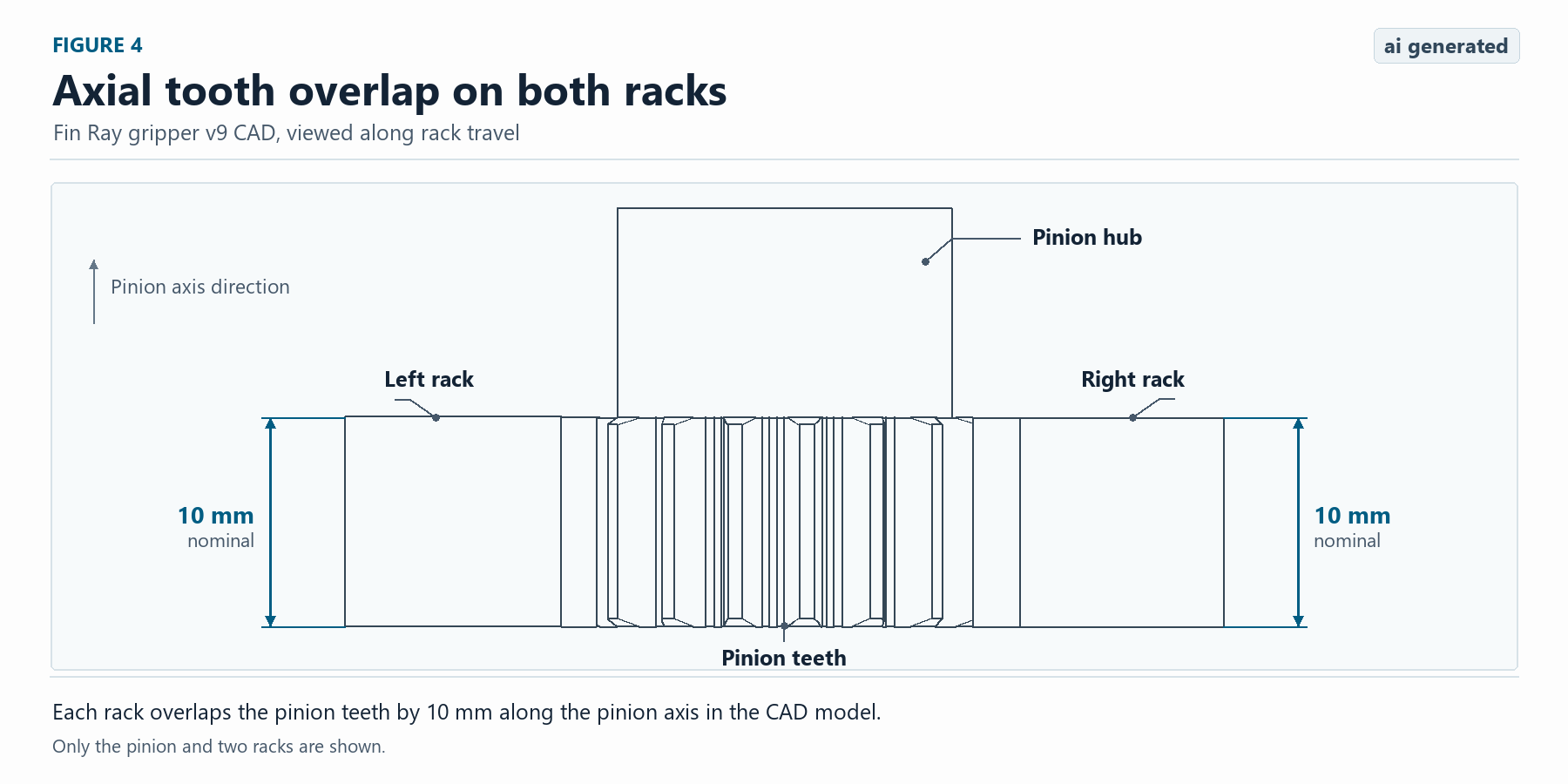
Figure 4. The v9 CAD model shows 10 mm of nominal axial overlap on each side.
During trial assembly, apply a thin layer of gear marking compound to several pinion tooth flanks. Follow the component instructions and turn the pinion slowly to bring the marked teeth through mesh at the inspection positions. Inspect the contact marks on each rack. If the marks consistently concentrate at one end of the tooth face, check the pinion’s axial position, whether its axis is parallel to the rack tooth traces across the face width, and how the rack seats on its mounting surface. See tooth contact patterns for examples.
How to Measure Rack and Pinion Backlash
With the pinion held against rotation, measure linear backlash as the distance the rack travels between contact on one set of tooth flanks and contact on the opposite set. Lost motion during reversal can also come from looseness between the pinion and shaft, play in the shaft support, or movement at a bracket.
Use the following method if the rack can move, each side can be checked separately, and the pinion can be held against rotation in its installed position.
-
Leave only the rack under test in mesh. At the measurement position, hold the pinion against rotation without shifting its axis or changing the mounting distance.
-
Mount a dial indicator on the frame. Set its probe parallel to the direction of travel against the rack end face or a measurement surface rigidly attached to the rack. Push lightly along the travel direction until the tooth flanks just make contact and zero the indicator. Push in the opposite direction with a similar light force until the opposite flanks just make contact. Record the change in reading.
-
Release the rotational restraint before moving to the next measurement point, then restrain the pinion again at that point. Repeat near both ends of the usable stroke, at mid-stroke, and at any tight spots that can be reached freely. If the reading changes noticeably with the applied force, check the indicator mount, the pinion restraint, the pinion-to-shaft connection, the shaft support, and the brackets. Then measure again.
Keep measurement points clear of mechanical stops and any position where the pinion starts to run off the end of the rack. Before comparing readings with a specified limit, confirm that the measurement direction and setup match the conditions in the component manual. The backlash measurement uses two indicators to measure relative motion. The single-indicator method above applies when the pinion can be held against rotation in place and the rack can move.
How to Check Full Travel After Tightening
Tighten the fasteners to specification, then run one full opening and closing cycle at low speed without a workpiece. If the mechanism binds, stop and record the position and direction of travel. Compare that point with your earlier single-rack checks. If the design allows the same single-rack setup, recheck backlash at that point using the procedure above. If the design allows you to disengage the pinion, move the carriage through the same point to check for resistance in the guide or interference at a travel stop.
Common Installation Problems and What to Check
| Error or symptom | What to check first |
|---|---|
| The overall rack height was used to set the mounting distance | Check the drawing for the height from the rack back-face datum to the pitch line. |
| The mechanism runs freely at mid-stroke but binds near one end | Compare resistance at the same point with the mesh engaged and disengaged. Check the mounting distance along the stroke and look for local interference. |
| Each side runs freely on its own, but the assembly binds with both racks engaged | Return to the reference jaw opening. Check both mounting distances and each rack’s position along the direction of travel. |
| The handwheel moves before the jaws respond on reversal | Check the handwheel and pinion connections to the shaft, shaft support play, and bracket movement. Then measure backlash on one side at a time. |
FAQs About Rack and Pinion Installation
Q: Why can the assembly bind even when the rack and pinion have the same module and pressure angle?
Installation errors can still make the mesh tight at certain points. Check the datums and mounting distance, then look for rack skew along the stroke.
Q: Why does the mechanism run freely in the middle but bind near one end?
If the design allows it, disengage the pinion and move the carriage through the tight spot. If resistance remains, inspect the guide and look for local interference. If it goes away, check the mounting distance and tooth contact at that position. See the full-travel check above.
Q: Should a rack and pinion be adjusted to zero backlash?
For a standard spur mesh, keep the backlash specified for the mating parts and check it at several points. If the application calls for less lost motion on reversal, consider a purpose-built anti-backlash or preloaded drive and follow its setup procedure.
Q: Why do both racks run freely on their own but bind when assembled together?
Check the mounting distance on both sides. Then set the carriages to the positions for the specified jaw opening and verify that both racks can engage at the same pinion angle. See the opposed-rack checks above.
Keep Learning
Rack and Pinion Installation: Alignment and Backlash
Key Takeaways Use the component drawings to set the nominal mounting distance from the rack datum to the pinion axis. Check carriage travel with the pinion disengaged, then align the rack to the carriage’s actual direction of travel. For two opposed racks, check both mounting distances and verify that both racks mesh at the specified jaw opening. Check tooth contact and measure backlash at several points. After tightening, cycle the mechanism slowly through its full stroke without a workpiece. This ra......
Timing Belt and Pulleys: Precision Matching and Replacement Guide
Introduction Timing belts and pulleys play a very important role in the precise and complex transmission system. They are the key medium for power transmission and the core components for coordinating the precise operation of various mechanical parts according to the predetermined time and sequence. As the core component of power transmission, the rationality of its design and the quality of its material will directly affect the stability and service life of the entire transmission system. Therefore, ......
How to Use and Install a Cotter Pin
I. Introduction Cotter pins are essential mechanical fasteners used to secure parts in place, preventing unintended movement or loosening. They are widely used in machinery, automotive, and industrial applications due to their simple yet effective locking mechanism. This guide will provide an in-depth look at cotter pins, their types, usage, and installation process, making it a valuable resource for mechanical enthusiasts and professionals. II. What is a Cotter Pin? A cotter pin is a metal fastener, ......
Top 3 Types of Shaft Couplings and How to Install Them Like a Pro
Alt: A picture of Rigid Couplings When it comes to industrial machinery, the smallest connection can make the biggest impact. Shaft couplings might not look like much, but they're responsible for transferring torque, compensating for misalignment, and reducing vibration between rotating components. From motor shaft couplings to drive shaft couplers, getting this component right is critical. The wrong coupling—or one installed carelessly—can mean early pillow block bearing wear, shaft damage, or even t......
How to Use and Install T-Nuts in T-Slot Aluminum?
When working with modular framing systems like T-slot aluminum, securing components reliably is critical. That’s where T-nut hardware comes in. T-nuts provide a sturdy, adjustable fastening solution that works seamlessly within the channels of T-slot aluminum profiles. In this guide, we’ll cover what T-nuts are, how to install them correctly, and how to overcome common issues—like dealing with a T-nut bolt budge or how to loosen a nut that won't budge. What Is a T-Nut Hardware? T-nut hardware refers t......
Perfect Door Installation: How to Install Hinges on a Door
Installing door hinges is a fundamental skill for any DIYer or professional carpenter. Whether you're installing a new door or adjusting existing hinges, understanding the correct way to install, adjust, and maintain your door hinges will ensure a smooth and secure operation. This guide will cover how to put hinges on a door, how to adjust door hinges, and more, with a special focus on the right door hinges for various applications. Choosing the Right Hinges for Your Door Before installing door hinges......