NEMA Stepper Motor Sizes, Specifications, and Frame Size Chart Explained
10 min
- What Does NEMA Mean?
- NEMA Stepper Motor Sizes
- Typical NEMA Stepper Motor Dimensions Reference Chart
- How to Measure Stepper Motor Dimensions
- Why Do Motors with the Same NEMA Size Differ?
- FAQs
- Conclusion
NEMA stepper motor sizes standardize the mechanical interface—faceplate width, bolt pattern, and pilot diameter—but leave torque, thermal behavior, and high-speed performance to the manufacturer's design choices. Conflating frame size with motor capability is a frequent source of integration failure.
The following sections detail the exact dimensions of each NEMA frame and explain how to read the specifications that actually determine whether a motor will work in your application.
What Does NEMA Mean?
Before explaining NEMA stepper motor sizes, we first need to understand what NEMA is.
NEMA stands for the National Electrical Manufacturers Association, a U.S.-based organization that defines standards for electrical equipment. In the context of stepper motors, "NEMA size" refers specifically to the faceplate mounting standard—not the motor's electrical performance, torque output, or shaft configuration.
The NEMA standard governs three critical mechanical interfaces:
- Mounting hole pattern: Center-to-center distances and thread specifications
- Pilot diameter: The diameter of the locating boss used to align the motor concentrically with the mounting surface.
- Mounting Hole Pattern: The standardized hole spacing used for mounting compatibility.
The NEMA designation system for stepper motors is primarily a mechanical mounting standard. It defines key interface dimensions such as the faceplate size, mounting hole pattern, and pilot diameter, but does not specify performance characteristics like torque, current, inductance, or step angle.
A "NEMA 17" motor does not indicate a dimension of 17 inches or 17 millimeters. Instead, it refers to a standardized frame size used to ensure mounting compatibility across manufacturers.
Originally developed in North America, NEMA frame sizes have become the industry standard for stepper motors used in automation, CNC machinery, robotics, and 3D printing. While IEC standards are common for larger industrial motors, they are rarely applied to the stepper motor sizes covered in this guide.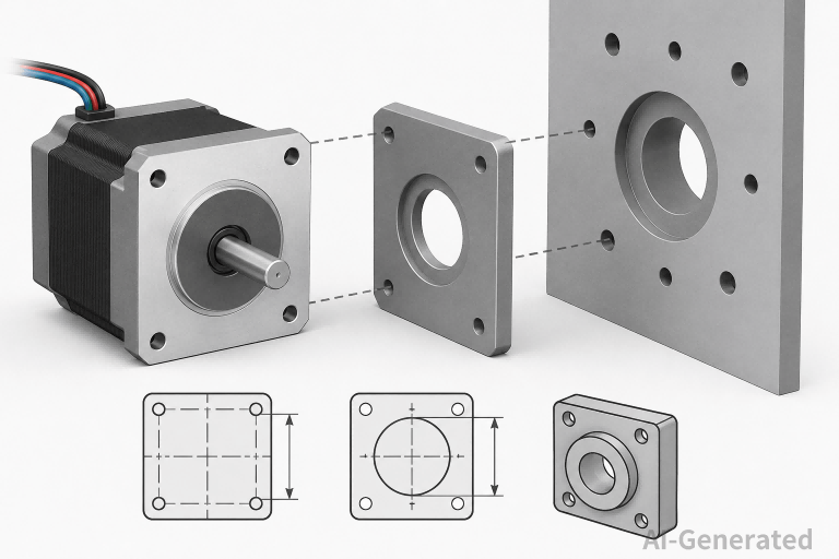
NEMA Stepper Motor Sizes
Key Physical Dimensions
The NEMA number roughly correlates with the motor's faceplate width in tenths of an inch. A NEMA 17 motor has a faceplate approximately 1.7 inches (43.2 mm) wide. This is a rough correlation, not an exact measurement.
The critical dimensions for each frame size are:
| Dimension | Description | Why It Matters |
| Face width | The square (or sometimes round) front face of the motor | Determines if the motor fits your mounting bracket |
| Mounting hole spacing | Distance between diagonal mounting holes | Must match your plate drilling pattern exactly |
| Pilot diameter | The raised circular boss on the faceplate | Ensures shaft concentricity with your load |
| Shaft diameter | Output shaft size | Coupler, pulley, or gearbox selection depends on this |
| Shaft length | Exposed shaft beyond the faceplate | Affects belt tensioning and coupling engagement |
| Body length | Total motor depth | Clearance in compact assemblies; correlates with torque |
Units and Conversions
NEMA standards originate in imperial units, but most modern datasheets list both imperial and metric. Key conversions to remember:
- 1 inch = 25.4 mm
- NEMA 23 = 2.3 inches ≈ 57 mm face width (not 58 mm, though some manufacturers round this)
- NEMA 34 = 3.4 inches ≈ 86 mm face width
Engineers working in metric environments should verify actual mounting dimensions rather than relying on the NEMA number conversion. Some Asian manufacturers produce "NEMA 17" motors with 42 mm face widths (slightly under true 1.7 inches), and they fit standard NEMA 17 mounts without issue. The tolerance band in the standard allows this.
Typical NEMA Stepper Motor Dimensions Reference Chart
The dimensions below represent commonly used industry reference values. Actual dimensions may vary slightly among manufacturers. Always verify critical dimensions using the official datasheet before finalizing a design.
| NEMA Size | Face Width (in) | Face Width (mm) | Mounting Hole Spacing (mm) | Pilot Diameter (mm) | Shaft Diameter (mm) | Typical Body Length Range (mm) | Common Applications |
| NEMA 8 | 0.8 | 20.3 | 16 | Ø16 | 3 | 20 – 30 | Medical devices, micro-positioning, optics |
| NEMA 11 | 1.1 | 28 | 23 | Ø22 | 4 | 28 – 40 | Semiconductor handling, small pumps |
| NEMA 14 | 1.4 | 35 | 26 | Ø22 | 5 | 20 – 48 | Compact CNC, instrumentation |
| NEMA 17 | 1.7 | 43.2 | 31 | Ø22 | 5 | 25 – 60 | 3D printers, desktop CNC, automation |
| NEMA 23 | 2.3 | 57 | 47.1 | Ø38.1 | 6.35 (1/4") or 8 | 41 – 112 | CNC mills, laser cutters, medium automation |
| NEMA 34 | 3.4 | 86 | 69.6 | Ø73 | 9.5 (3/8") or 14 | 66 – 156 | Industrial machinery, large format CNC |
| NEMA 42 | 4.2 | 110 | 89 | Ø55.5 | 16 or 19 | 100 – 200+ | Heavy industrial, large positioning tables |
How to Measure Stepper Motor Dimensions
When replacing a motor or designing a new mount without a datasheet, measure in this order:
- Face width: Measure the square faceplate across the flats. Round to the nearest standard NEMA size.
- Mounting hole spacing: Measure center-to-center on diagonal holes. This is the most reliable identifier.
- Pilot diameter: Check if a raised boss exists. Measure its diameter with calipers.
- Shaft diameter: Measure across the flats if the shaft is D-cut; otherwise measure full diameter.
Body length: Measure from faceplate to rear cap. Do not include the connector or cable exit.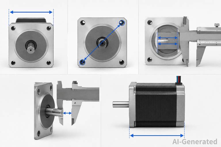 Common measurement errors:
- Measuring hole spacing edge-to-edge instead of center-to-center
- Confusing the pilot diameter with the bolt circle
- Measuring body length including the rear shaft (if present) or connector housing
- Assuming shaft diameter from NEMA size alone—always verify
If the motor has a rear shaft extension (for encoder mounting), that length is not part of the NEMA standard. Account for it separately in your clearance checks.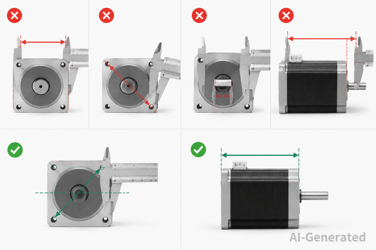
Why Do Motors with the Same NEMA Size Differ?
Two NEMA 17 motors can produce dramatically different torque, run at different temperatures, and require different drive currents. The NEMA standard only fixes the mounting interface. Everything else is manufacturer-specific.
Stack Length and Torque
The most significant variable is rotor and stator stack length—the depth of the laminated steel core inside the motor. A "long-body" NEMA 17 (55–60 mm) typically delivers 2–3× the holding torque of a "pancake" NEMA 17 (25–30 mm).
| Body Length Category | Typical Holding Torque (NEMA 17) | Thermal Considerations |
| Short (25–34 mm) | 13–18 N·cm | Low thermal mass; heats quickly under load |
| Standard (40–48 mm) | 40–59 N·cm | Balanced thermal performance |
| Long (55–60 mm) | 70–85 N·cm | Higher thermal mass; requires better cooling |
Longer stacks increase winding resistance and inductance. A long NEMA 17 may need 24V or higher drive voltage to achieve the same step rate as a short NEMA 17 on 12V. Do not assume higher torque means better performance in high-speed applications.
Winding Variants
Manufacturers offer multiple winding configurations within the same frame:
- Resistance: 0.5 Ω to 50 Ω windings exist for NEMA 17
- Inductance: Determines current rise time; critical for high-speed performance
- Rated current: From under 0.5A to over 2A per phase
A low-resistance, high-current winding on a long NEMA 23 can deliver high torque but requires a powerful driver. Swapping in a motor with the same frame but different winding specs without recalibrating the drive current will cause missed steps or overheating.
Shaft and Bearing Options
Same NEMA size, different mechanical configurations:
Single shaft vs. dual shaft: Dual-shaft versions add 10–20 mm to overall length
- D-cut vs. full round: D-cut prevents coupler slippage but limits pulley bore options
- Flat machined on shaft: Alternative to D-cut for set-screw retention
- Bearing type: Standard sleeve bearings vs. ball bearings; ball bearings handle higher radial loads and last longer in belt-drive application
Connector and Lead Wire Variations
The NEMA standard does not specify electrical termination. Motors ship with:
- Bare leads (various gauge and length)
- JST connectors (common in 3D printer markets)
- Molex or AMP connectors (industrial preference)
- Integrated terminal boxes (NEMA 34 and larger)
Lead wire gauge matters for high-current windings. Thin 26 AWG leads on a 2A NEMA 23 motor will heat up and create a voltage drop. This is a hidden reliability issue not captured in the NEMA frame designation.
FAQs
What is the exact width of a NEMA 17 stepper motor?
Approximately 43.2 mm (1.7 inches). In practice, most motors labeled NEMA 17 measure 42 mm face width. The 0.3 mm difference is within manufacturing tolerance and does not affect mounting compatibility.
Can I replace a NEMA 17 with a NEMA 14 or NEMA 23?
No, not without changing the mounting plate. The bolt patterns are incompatible. NEMA 14 uses 26 mm diagonal spacing; NEMA 17 uses 31 mm; NEMA 23 uses 47.1 mm. Adapters exist but add stack height and compliance
Why does my NEMA 23 motor have an 8 mm shaft instead of 6.35 mm?
High-torque NEMA 23 variants often use larger shafts to handle higher radial loads. Check your coupler or pulley bore before ordering. A 6.35 mm bore coupler will not fit an 8 mm shaft.
Does a longer NEMA 17 motor always have more torque?
Generally yes, but only at low to moderate speeds. At high step rates, a shorter motor with lower inductance may outperform a longer motor driven at the same voltage. Check the torque-speed curve, not just the holding torque specification.
Are NEMA 17 and 42 mm motors the same thing?
Effectively yes in the current market. Most manufacturers label 42 mm face-width motors as NEMA 17. The 0.3 mm difference from true 1.7 inches (43.2 mm) is negligible for mounting purposes.
How do I identify a stepper motor size if the label is missing?
Measure the diagonal mounting hole spacing. This is the most reliable identifier. Compare against the chart above. Face width alone can be misleading if the motor has a non-square faceplate.
What is the difference between NEMA 34 and 86 mm motors?
They are the same frame size. NEMA 34 (3.4 inches) converts to 86.36 mm. "86 mm" is simply the metric designation used by many Asian manufacturers.
Can I use a NEMA 23 motor in a NEMA 23 mount from a different brand?
Usually yes, but verify three things: the diagonal hole spacing, the pilot diameter (if your mount uses it for location), and the shaft diameter. Some low-cost mounts have loose tolerances that accommodate minor variations.
Why do some NEMA 17 motors have different shaft lengths?
Shaft length is not standardized. Standard lengths are 20–24 mm, but custom lengths exist. If your pulley or coupler needs more engagement, order a long-shaft variant rather than shimming a short shaft.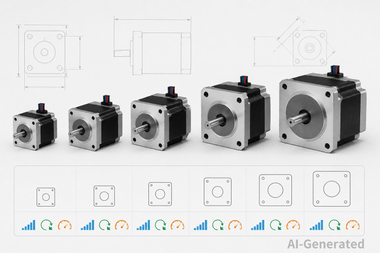
Conclusion
NEMA sizing is a mechanical mounting standard, not a performance specification. The number indicates faceplate dimensions and bolt patterns, leaving torque, speed, electrical characteristics, and thermal behavior to the manufacturer's design choices.
For engineering work, the critical takeaway is this: verify the mounting interface first, then evaluate electrical and mechanical variants within that frame. Two motors with identical NEMA numbers can require different drives, deliver different torque curves, and exhibit different thermal limits.
When selecting a stepper motor, use the NEMA chart to ensure physical fit, then dig into stack length, winding resistance, inductance, and shaft configuration to match the motor to your motion profile. The frame size gets you in the right category; the detailed specifications determine whether the motor actually works in your application.
Keep Learning
Closed Loop Stepper Motor: How It Works, Benefits, and Applications
Stepper motors have long been a go-to solution for precise positioning in industrial automation. But traditional open-loop stepper systems come with a well-known limitation: they have no way of knowing whether the motor actually reached its commanded position. If steps are lost due to a sudden load change or mechanical jam, the system carries on, unaware of the error. Closed loop stepper motors solve this problem by adding an encoder and a feedback-capable driver to the system. The result is a motor t......
Unipolar vs Bipolar Stepper Motor: Key Differences and How to Choose
You're looking at two NEMA 23 stepper motors with similar torque ratings on paper and a price difference that doesn't quite make sense. One is listed as bipolar, the other unipolar. The datasheet tells you the holding torque, rated current, and step angle, but it doesn't explain why the winding configuration matters — or whether it matters for your application. It does, but not always in the way most comparisons suggest. The performance difference between unipolar and bipolar motors starts with a simp......
Permanent Magnet Stepper Motor: How It Works and How to Choose the Right One
Introduction Permanent magnet stepper motors are widely used in applications such as printers, HVAC actuators, ticket dispensers, and laboratory devices, where reliable incremental motion is more important than ultra-high positioning accuracy. Unlike variable reluctance designs, PM stepper motors use a permanent magnet rotor that interacts directly with stator-generated magnetic fields to produce discrete movement. This design provides useful low-speed torque, straightforward control, and cost-effecti......
NEMA Stepper Motor Sizes, Specifications, and Frame Size Chart Explained
NEMA stepper motor sizes standardize the mechanical interface—faceplate width, bolt pattern, and pilot diameter—but leave torque, thermal behavior, and high-speed performance to the manufacturer's design choices. Conflating frame size with motor capability is a frequent source of integration failure. The following sections detail the exact dimensions of each NEMA frame and explain how to read the specifications that actually determine whether a motor will work in your application. What Does NEMA Mean?......
How to Select a Stepper Motor: Step-by-Step Guide
Introduction Proper stepper motor sizing is essential for achieving reliable positioning performance. Selecting the wrong stepper motor usually shows up as missed steps, excess heat, or stalled motion mid-cycle. The root cause is rarely the motor itself—more often, the selection process skipped load verification or assumed catalog torque ratings apply directly to the application. This guide breaks down a practical sizing workflow. It covers torque calculations, motion profile definition, and the drive......
Optimizing Stepper Motor Speed: Factors, Dynamics, and Control Strategies
Introduction Stepper motor speed optimization is where electrical drive design meets mechanical dynamics. Push too hard without voltage margins, and mid-band resonance stalls the rotor. Run overly conservative profiles on a high-inertia gantry, and cycle times suffer. The real challenge isn't hitting a datasheet RPM—it's maintaining positional accuracy as load, driver, and thermal conditions shift. Understanding stepper motor speed limits, measurement methods, and control strategies is essential for b......