How to Select a Stepper Motor: Step-by-Step Guide
9 min
- Introduction
- Key Factors in Stepper Motor Sizing
- Defining Motion Requirements
- Load and Torque Calculations
- Motor Selection
- Driver and Power Supply Selection
- Quick Selection Guide
- Common Sizing Mistakes
- FAQs
- Conclusion
Introduction
Proper stepper motor sizing is essential for achieving reliable positioning performance. Selecting the wrong stepper motor usually shows up as missed steps, excess heat, or stalled motion mid-cycle. The root cause is rarely the motor itself—more often, the selection process skipped load verification or assumed catalog torque ratings apply directly to the application.
This guide breaks down a practical sizing workflow. It covers torque calculations, motion profile definition, and the driver/power supply pairing that actually determines whether a motor delivers its rated performance. The focus is on actionable criteria rather than theoretical completeness.
Key Factors in Stepper Motor Sizing
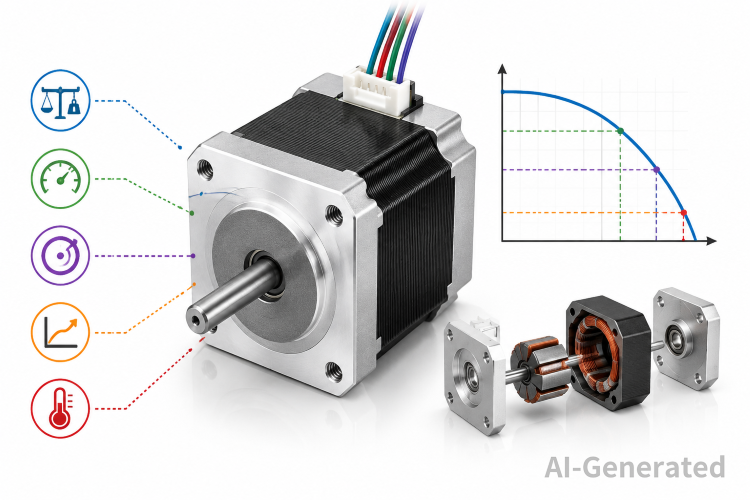
Five variables drive the decision. Ignore any one of them and the system may work in testing but fail under production conditions.
| Factor | What It Determines | Common Oversight |
| Load Torque | Continuous torque the motor must overcome | Underestimating friction in leadscrew or belt systems |
| Acceleration Torque | Peak torque during speed changes | Treating peak torque as the only torque that matters |
| Inertia Ratio | How responsive the system feels | Ignoring rotor inertia in high-speed indexing |
| Speed Range | Whether torque is available where needed | Assuming holding torque applies at 500 RPM |
| Duty Cycle | Thermal limits and current derating | Running 100% duty at peak current without heatsinks |
Motor frame size (NEMA 17, 23, 34) only indicates mounting dimensions. Two NEMA 23 motors can differ by 50% in torque output. The critical document is the torque-speed curve, not the frame designation.
Defining Motion Requirements
Start with the move profile, not the motor catalog.
Required parameters:
- Move distance per cycle (mm, degrees, or steps)
- Move time or throughput requirement (parts per minute)
- Positioning accuracy (±0.1 mm vs ±0.01 mm changes microstepping and feedback strategy)
- Load mass and geometry (affect reflected inertia)
- Transmission type (leadscrew pitch, pulley diameter, gearbox ratio)
A fast, short move with frequent direction changes needs high acceleration torque. A slow, continuous rotation needs sustained torque at low speed with thermal headroom. These two cases select completely different motors even if the load weight is identical.
Practical tip: Define the worst-case move first. If the motor handles the heaviest acceleration segment, it will handle everything else. Do not average the duty cycle across the entire day—size for the peak repeating cycle.
Load and Torque Calculations
Total required torque splits into two components:
Friction Torque (T_f): The torque needed to maintain constant velocity against bearing friction, screw resistance, and preload.
Acceleration Torque (T_a): The torque needed to change velocity, determined by load inertia and acceleration rate.
Load Inertia Reflection
For a leadscrew system:
Jref = mp2 /4 π2
Where:
- m = mass of linear load
- p = screw lead (meters per revolution)
The total inertia seen by the motor is:
Jtotal = Jmotor + Jref
Where:
- Jmotor=motor rotor inertia (from datasheet)
- Jref =reflected load inertia
- For a belt/pulley system:
- Jref =mr2
Where:
r = pulley radius (m)
m=linear load mass (kg)
The same total inertia relationship applies:
Jtotal = Jmotor + Jref
Acceleration Torque
Tα= ( Jmotor + Jref )α
Where α = angular acceleration (rad/s²).
Total Torque Requirement
Trequired= Tf +Tα
Apply a safety factor of 1.5 to 2.0 for unmodeled friction, voltage sag, and temperature effects. A motor running at 90% of its rated torque continuously will overheat. A motor running at 50% leaves margin for mechanical wear over time.
Critical distinction: Catalog torque ratings are typically holding torque (motor stationary, full current). Running torque at speed can be 30–60% lower depending on driver voltage and winding inductance. Always compare required torque against the torque-speed curve at your target RPM, not the holding torque number.
Motor Selection
Torque-Speed Curve Verification
Plot or tabulate your required torque at each phase of the move:
| Move Phase | Speed (RPM) | Required Torque (Nm) | Motor Available Torque (Nm) | Margin |
| Acceleration | 0–300 | 0.45 | 0.80 | 78% |
| Constant Speed | 300 | 0.15 | 0.55 | 267% |
| Deceleration | 300–0 | 0.40 | 0.80 | 100% |
If any phase drops below 30% margin, reconsider the motor or the motion profile.
Step Angle and Microstepping Reality
- 1.8° Stepper (200 steps/rev): The most common choice for motion-control applications, offering a good balance of torque, speed, and positioning performance.
- 0.9° Stepper (400 steps/rev): Provide higher native resolution, smoother motion, and reduced resonance. For the same frame size, they generally deliver lower torque than comparable 1.8° motors, making them suitable for precision positioning applications.
Microstepping (1/8, 1/16, 1/32) improves smoothness and resolution but does not proportionally increase torque. At 1/16 microstepping, the motor still produces roughly the same torque as full-step; it just divides the step into smaller increments. Do not select a smaller motor assuming microstepping compensates for mechanical load.
Winding Configuration
Bipolar motors with lower inductance (e.g., 2–4 mH) maintain torque better at high speed when driven by sufficient voltage. High-inductance windings (10+ mH) work for slow, high-torque applications but torque drops sharply above a few hundred RPM unless driven by very high voltage.
Driver and Power Supply Selection
The motor does not operate in isolation. Driver voltage and current control determine how much of the motor's torque curve is usable.
Driver Voltage
Rule of thumb:
Vsupply ≈32·√L
Where L = winding inductance in mH.
Examples:
| Winding Inductance | Suggested Voltage | Typical Application |
| 1–2 mH | 24–36 V | High-speed pick-and-place |
| 3–5 mH | 36–48 V | CNC milling, general automation |
| 8–12 mH | 60–80 V | Low-speed, high-torque loads |
Higher voltage pushes current into the windings faster during each step, extending usable torque to higher RPMs. A 24 V supply on a high-inductance motor will severely limit top speed.
Current Setting
Set the driver current to the motor's rated current (per phase), not higher. Modern chopper drivers regulate current, but if the driver setting exceeds the motor rating, continuous operation causes thermal damage. If the application requires more torque, use a bigger motor—not a higher current setting.
Power Supply Sizing
Do not size the supply by multiplying motor rated current by phase count. A chopper driver draws current in pulses, and two motors rarely peak simultaneously.
Conservative estimate:
Isupply = 0.7 (Imotor1 + Imotor2 + ...)
For a single NEMA 23 motor rated at 2.8 A/phase, a 4 A 48 V supply is typically sufficient. Add 20% headroom for supply aging and input voltage variation.
Quick Selection Guide
Use this sequence to avoid backtracking:
- Define peak load torque (friction + worst-case acceleration)
- Add 1.5× safety factor → target torque
- Check torque-speed curve at maximum operating RPM
- Verify inertia ratio (load inertia / motor inertia < 10:1 for open loop; < 3:1 for aggressive acceleration)
- Select driver voltage based on winding inductance
- Size power supply at ~70% of summed motor currents
- Test thermal rise after 30 minutes of production cycling
If any step fails, the cheapest fix is usually a mechanical change (lighter carriage, coarser screw pitch, pulley ratio) rather than jumping to a larger motor frame.
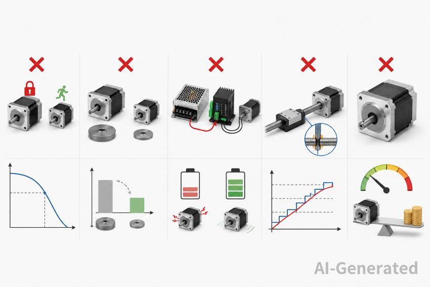
Common Sizing Mistakes
Assuming holding torque equals running torque
Holding torque is measured at zero speed. At 500 RPM, available torque may drop to 40% of that value. Always reference the speed-specific torque curve.
Ignoring rotor inertia in high-indexing applications
A small motor with low torque but very low rotor inertia can out-accelerate a larger motor in short, fast moves. Inertia matching sometimes matters more than peak torque.
Selecting voltage based on controller convenience
Using a 24 V supply because it matches the PLC voltage is a common shortcut. If the motor inductance demands 48 V, the system will stall or skip steps at speed regardless of how convenient the wiring is.
Over-relying on microstepping for precision
Microstepping improves smoothness but mechanical backlash and leadscrew error often dominate positioning accuracy. A 1/32 microstep on a 5 mm leadscrew yields ~8 µm theoretical resolution; mechanical compliance may consume half of that.
Oversizing "just to be safe"
A motor with 3× required torque runs cooler but has higher rotor inertia, may exhibit more resonance, and costs more to drive. Size for 50–70% utilization at peak load, not 10%.
FAQs
What is the most critical parameter in stepper motor sizing?
Available torque at the application's maximum operating speed. Holding torque is irrelevant if the motor cannot deliver sufficient torque during the actual move.
Does microstepping increase motor torque?
No. Microstepping improves resolution and reduces resonance. Torque per microstep is lower; the motor's maximum usable torque remains essentially the same as in full-step mode.
Can I run a stepper motor without a gearbox?
Yes, if the reflected load inertia is within 10:1 of the motor rotor inertia and the required speed falls within the motor's torque curve. Gearboxes solve inertia mismatch and multiply torque, but introduce backlash.
How do I know if my power supply is undersized?
Voltage sag during acceleration causes missed steps or erratic noise. Measure supply voltage under load; if it drops more than 5–10%, increase supply capacity or reduce acceleration.
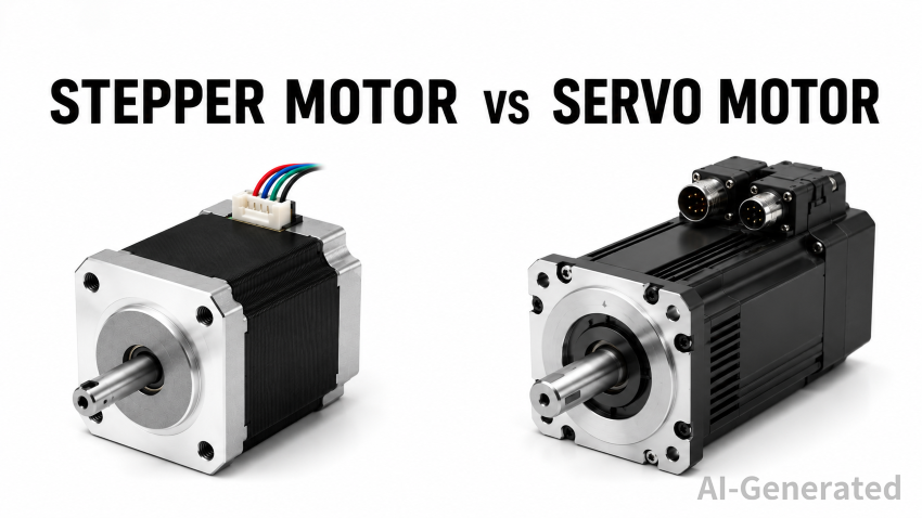
When should I choose a servo motor instead?
If the application requires closed-loop positioning at high speed, variable load conditions, or continuous operation where stepper overheating is unavoidable. Steppers excel in fixed-profile, moderate-speed positioning where cost and simplicity matter.
Conclusion
Proper stepper motor sizing is a matching exercise between mechanical load, motion profile, and electrical drive capability. The motor datasheet provides a starting point, but the torque-speed curve under actual driver voltage defines real-world performance. Verify torque at speed, check inertia ratios, and size the power supply for peak demand—not nominal averages. Getting these three elements right eliminates most field failures without requiring larger or more expensive hardware.
Keep Learning
Closed Loop Stepper Motor: How It Works, Benefits, and Applications
Stepper motors have long been a go-to solution for precise positioning in industrial automation. But traditional open-loop stepper systems come with a well-known limitation: they have no way of knowing whether the motor actually reached its commanded position. If steps are lost due to a sudden load change or mechanical jam, the system carries on, unaware of the error. Closed loop stepper motors solve this problem by adding an encoder and a feedback-capable driver to the system. The result is a motor t......
Unipolar vs Bipolar Stepper Motor: Key Differences and How to Choose
You're looking at two NEMA 23 stepper motors with similar torque ratings on paper and a price difference that doesn't quite make sense. One is listed as bipolar, the other unipolar. The datasheet tells you the holding torque, rated current, and step angle, but it doesn't explain why the winding configuration matters — or whether it matters for your application. It does, but not always in the way most comparisons suggest. The performance difference between unipolar and bipolar motors starts with a simp......
Permanent Magnet Stepper Motor: How It Works and How to Choose the Right One
Introduction Permanent magnet stepper motors are widely used in applications such as printers, HVAC actuators, ticket dispensers, and laboratory devices, where reliable incremental motion is more important than ultra-high positioning accuracy. Unlike variable reluctance designs, PM stepper motors use a permanent magnet rotor that interacts directly with stator-generated magnetic fields to produce discrete movement. This design provides useful low-speed torque, straightforward control, and cost-effecti......
NEMA Stepper Motor Sizes, Specifications, and Frame Size Chart Explained
NEMA stepper motor sizes standardize the mechanical interface—faceplate width, bolt pattern, and pilot diameter—but leave torque, thermal behavior, and high-speed performance to the manufacturer's design choices. Conflating frame size with motor capability is a frequent source of integration failure. The following sections detail the exact dimensions of each NEMA frame and explain how to read the specifications that actually determine whether a motor will work in your application. What Does NEMA Mean?......
How to Select a Stepper Motor: Step-by-Step Guide
Introduction Proper stepper motor sizing is essential for achieving reliable positioning performance. Selecting the wrong stepper motor usually shows up as missed steps, excess heat, or stalled motion mid-cycle. The root cause is rarely the motor itself—more often, the selection process skipped load verification or assumed catalog torque ratings apply directly to the application. This guide breaks down a practical sizing workflow. It covers torque calculations, motion profile definition, and the drive......
Optimizing Stepper Motor Speed: Factors, Dynamics, and Control Strategies
Introduction Stepper motor speed optimization is where electrical drive design meets mechanical dynamics. Push too hard without voltage margins, and mid-band resonance stalls the rotor. Run overly conservative profiles on a high-inertia gantry, and cycle times suffer. The real challenge isn't hitting a datasheet RPM—it's maintaining positional accuracy as load, driver, and thermal conditions shift. Understanding stepper motor speed limits, measurement methods, and control strategies is essential for b......