Explore Different Types of Gears and Their Applications
6 min
- Introduction
- The Simplest Form: Gears with Teeth
- Parallel Axis Gears: The Most Common Configurations
- Cross-Axis Gear Types: 90-Degree Drive – Various Gear Types
- Non-Intersecting, Non-Parallel Axis Gear Types
- Specific Gear Styles and Application of Gears in the Real World
- Conclusion
- FAQs
Introduction
The gear is the basis of mechanical power transmission. Gears are like wheels with teeth, and they have two special features: They form a relationship between the speed of things (typically an engine and wheels). They change the direction of something. Virtually every mechanical device utilizes some type of gear, and gears are modified for a multitude of specialized applications.
This guide provides a comprehensive breakdown of common and specialized gear types, exploring their unique functional advantages to help you make informed design decisions. However, the performance of any gear type is ultimately dictated by the precision of its manufacture. To understand how the subtle geometry of individual teeth influences system noise and efficiency, we recommend exploring our detailed analysis of [Gear Toothing] and its role in high-performance tooth profile design.
The Simplest Form: Gears with Teeth
One fundamental characteristic of gears is that they have teeth, which are essential to their function. In fact, the definition of a gear lies in its toothing. A rotating component can only be considered a gear if it has teeth specifically designed to mesh with the teeth of another gear.
So, do gears have teeth? Yes, always. These teeth mesh with the teeth of another gear, thereby transmitting mechanical power from one shaft to another. The number, profile, pressure angle, pitch, and spacing affect the performance, efficiency, and load capacity of a gear pair.
Why Gear Sizes and Shapes Vary: Functionality Explained
Gears of varying sizes and shapes are employed to produce various mechanical results. When it comes to gear sizes, their manipulation allows engineers to:
- Increase or reduce rotational speed
- Multiply torque
- Reverse the direction of motion
- Change the motion type of rotation into the motion type of translation.
Gears are the flexible links that help us control mechanical systems, from conveyor belts to car drivetrains.
Parallel Axis Gears: The Most Common Configurations
The parallel axis gear is the most prevalent type of gear. The input and output shafts of such systems are coextensive.
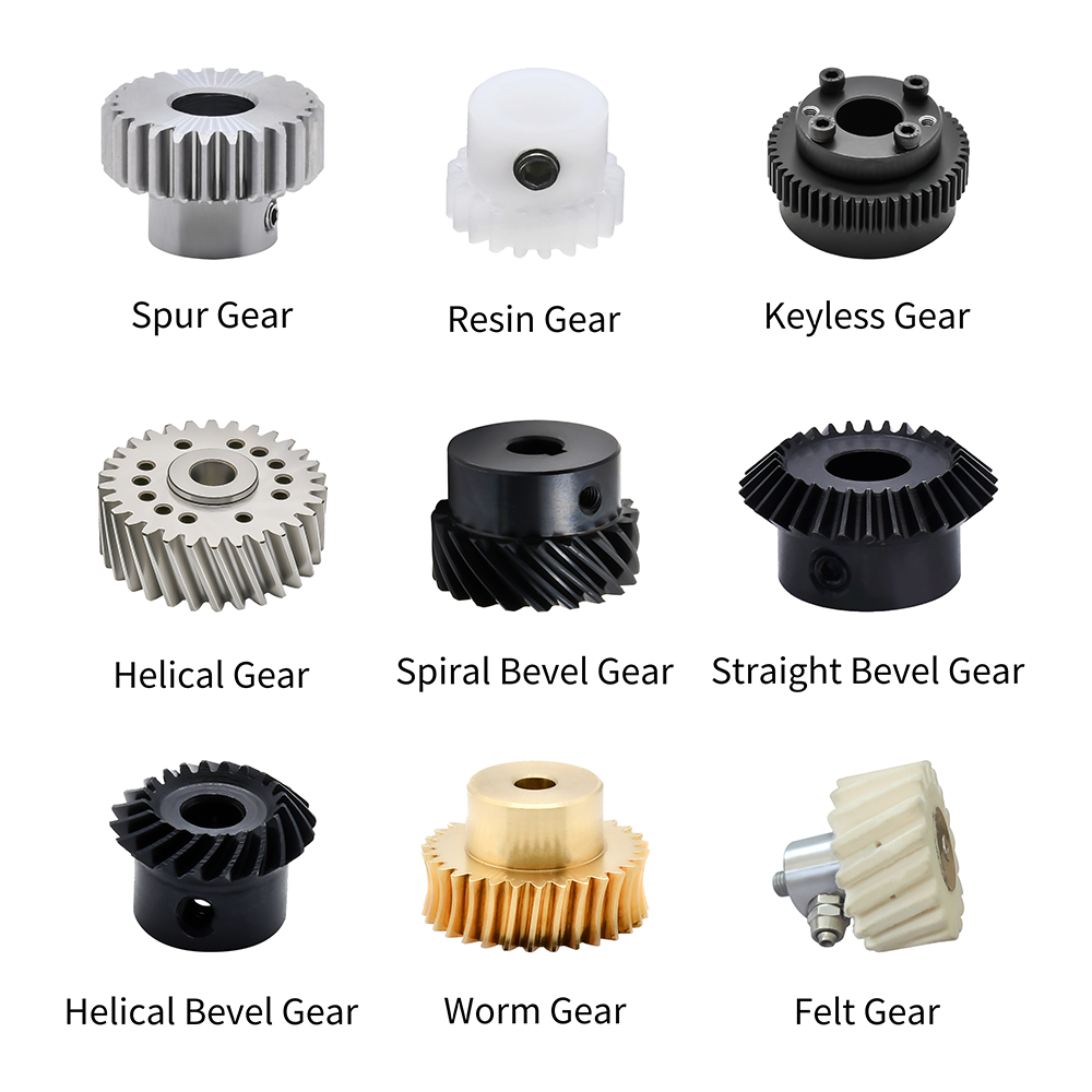
Spur Gears: The Most Straightforward Gear and Its Variants
Spur Gears are the simplest and probably most common type of gear found in mechanical systems. Their teeth are straight and parallel to the rotation axis of the gear.
Key characteristics:
- Simple design
- High efficiency
- Easy to manufacture
- For low to med speed only
Applications:
Spur gears are used in mechanisms such as pedal bicycles and many types of simple machinery.
Helical and Double Helical Gears
The teeth of helical gears are slanted, so the engagement takes place little by little. The result is a smoother and quieter operation than spur gears.
Advantages of helical gears:
- Reduced noise
- Higher load capacity
- Better performance at high speeds
Herringbone gears or double helical gears have a pair of helices having the same sense of rotation. This design naturally eliminates axial thrust and is therefore suited for predominantly high-pressure pulsating loads such as actuation, wear parts, and landing gear struts.
Cross-Axis Gear Types: 90-Degree Drive – Various Gear Types
When there is a power transmission requirement between intersecting shafts (commonly at right angles), bevel gear types are utilized.
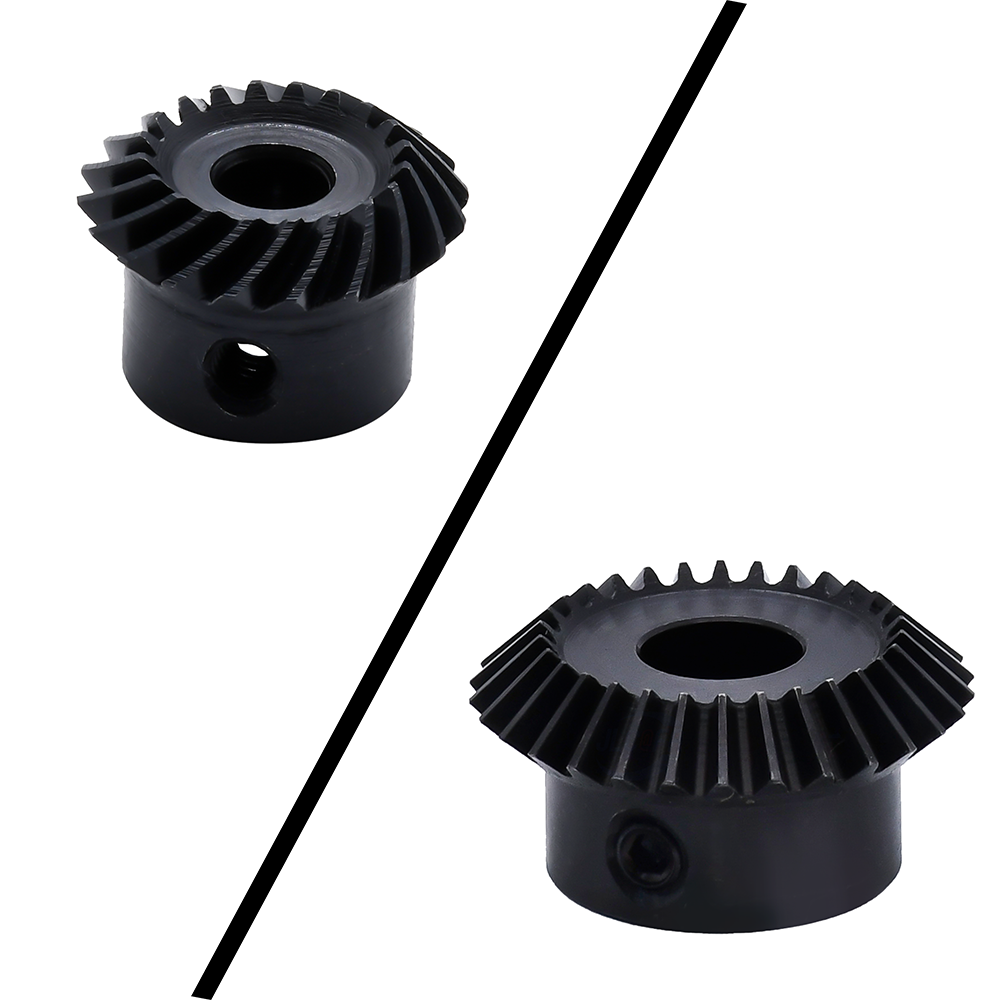
Bevel Gears: Classification and Subtypes
Conical / Bevel Gears are a process of transmitting power between two shafts that intersect at one point.
Common types include:
- Straight bevel gears
- Spiral bevel gears
Gears that are straight up are simple, but howl at higher speeds. Instead of straight teeth, which both involute and cycloidal gears use to transfer power as efficiently as possible, spiral bevel gears have curved teeth.
Applications:
- Differentials
- Power tools
- Printing machinery
- Industrial gearboxes
Hypoid Gear and Some Special Applications Thereof
Hypoid gears have a near resemblance to spiral bevel gears but work between non-intersecting axes. This compensatory construction finds an increase in torque transmission.
Common use:
Automotive rear drive axles require durability and smooth operation.
Non-Intersecting, Non-Parallel Axis Gear Types
Certain gear systems work with shafts that aren’t parallel or intersecting.
Worm Wheel Gears Types
Worm and worm wheel systems are used in a variety of ways.
Key features:
- Very high reduction ratios
- Compact design
- Self-locking capability in many cases
Worm gear types are highly self-locking and generally found in elevators, screw jack and conveyors where the backdriving is undesirable.
Rack and Pinion – Rotary Becoming Linear
Rack and pinion systems are, in fact, a special "gearless" type of gearing.
Applications include:
- Steering systems
- CNC machines
- Automated gates
- Linear actuators
The system described here is an interesting illustration of the way in which two different types of gear can fulfill separate mechanical roles.
Specific Gear Styles and Application of Gears in the Real World
Gears and Planetary Gear Arrangements
Inside the transmission enclosure, an internal gear, depending on its size, may be received.
Internal gear teeth are cut into the inside surface of a hollow cylinder. These gears are frequently related to planetary arranged gear systems, such as:
- Sun gear
- Planet gears
- Ring (internal) gear
Planetary systems have high torque density (torque delivered per unit volume), making them a great fit for robotics, wind turbines, and automatic transmissions, among other applications.
Conclusion
It is this versatility in gear type that is the basis of the mechanical transmission. From basic spur gears to more advanced planetary assemblies, every gear design has a purpose and was developed to solve an engineering problem.
Knowing all about the characteristics, advantages, and limitations of various types of gears is very important for an engineer, designer, and end user. If you are looking for maximum torque, speed control, or need to change the direction of rotation on a gearmotor, then selecting the proper gears is key for long-lasting operation.
To help you make the best choice, we offer a variety of gear types to meet different application needs. We invite you to explore JLCMC's diverse gear series to find the solution that best fits your project.
FAQs
How To Select The Appropriate Gear Type For Your Application?
Gear selection is based on the load, speed, shaft position, space limitations, and noise requirements. Parallel-axis gears are designed for simple or flange-mounted configurations, while planetary sets or worm-and-worm gear trains provide high torque density and significant reduction ratios within a compact footprint.
What Are Gears Typically Made From?
Gears are generally made from steel, alloy steels, cast iron, brass, bronze, or various engineering plastics. Material selection will be influenced by load, environmental, and wear conditions.
Why Do Some Gears Make More Noise Than Others?
Due to the gradual engagement of teeth and a higher contact ratio, helical gears offer much smoother and quieter operation compared to spur gears.
Keep Learning
Servo Motor Control System: A Complete Guide to Components, Working Principles, and Selection
Every axis of motion in a modern factory — from a CNC spindle interpolating a contour to a robotic arm placing a chip on a PCB — depends on a servo motor control system doing its job in the background. The system coordinates a motor, a drive, a feedback device, and a controller in a continuous closed loop, correcting position errors thousands of times per second. This guide breaks down how a servo motor control system works, what each component does, how the three control modes differ in practice, and......
Closed Loop Stepper Motor: How It Works, Benefits, and Applications
Stepper motors have long been a go-to solution for precise positioning in industrial automation. But traditional open-loop stepper systems come with a well-known limitation: they have no way of knowing whether the motor actually reached its commanded position. If steps are lost due to a sudden load change or mechanical jam, the system carries on, unaware of the error. Closed loop stepper motors solve this problem by adding an encoder and a feedback-capable driver to the system. The result is a motor t......
Unipolar vs Bipolar Stepper Motor: Key Differences and How to Choose
You're looking at two NEMA 23 stepper motors with similar torque ratings on paper and a price difference that doesn't quite make sense. One is listed as bipolar, the other unipolar. The datasheet tells you the holding torque, rated current, and step angle, but it doesn't explain why the winding configuration matters — or whether it matters for your application. It does, but not always in the way most comparisons suggest. The performance difference between unipolar and bipolar motors starts with a simp......
Permanent Magnet Stepper Motor: How It Works and How to Choose the Right One
Introduction Permanent magnet stepper motors are widely used in applications such as printers, HVAC actuators, ticket dispensers, and laboratory devices, where reliable incremental motion is more important than ultra-high positioning accuracy. Unlike variable reluctance designs, PM stepper motors use a permanent magnet rotor that interacts directly with stator-generated magnetic fields to produce discrete movement. This design provides useful low-speed torque, straightforward control, and cost-effecti......
NEMA Stepper Motor Sizes, Specifications, and Frame Size Chart Explained
NEMA stepper motor sizes standardize the mechanical interface—faceplate width, bolt pattern, and pilot diameter—but leave torque, thermal behavior, and high-speed performance to the manufacturer's design choices. Conflating frame size with motor capability is a frequent source of integration failure. The following sections detail the exact dimensions of each NEMA frame and explain how to read the specifications that actually determine whether a motor will work in your application. What Does NEMA Mean?......
How to Select a Stepper Motor: Step-by-Step Guide
Introduction Proper stepper motor sizing is essential for achieving reliable positioning performance. Selecting the wrong stepper motor usually shows up as missed steps, excess heat, or stalled motion mid-cycle. The root cause is rarely the motor itself—more often, the selection process skipped load verification or assumed catalog torque ratings apply directly to the application. This guide breaks down a practical sizing workflow. It covers torque calculations, motion profile definition, and the drive......