Stepper Motor Noise: Causes, Diagnosis, and Reduction Strategies
6 min
- Anatomy of Stepper Motor Noise
- Causes and Mechanisms
- Measurement and Diagnostics
- Practical Noise Reduction Strategies
- Maintenance and Longevity
- FAQ
- Conclusion
Stepper motor noise is a system-level problem. It emerges from the interaction between electromagnetic excitation, mechanical structure, and control strategy. Eliminating it requires distinguishing whether the root cause sits in the drive waveform, the mechanical assembly, or the resonance characteristics of the full system.
Anatomy of Stepper Motor Noise
Stepper motor noise splits into three categories with distinct spectral signatures.
| Noise Type | Primary Source | Frequency Range | Tonal Quality |
| Mechanical | Bearings, gears, couplings | Broadband, >1 kHz | Harsh, irregular |
| Electromagnetic | Torque ripple, cogging | Step frequency + harmonics | Whining, humming |
| Aerodynamic | Rotor ventilation | >3 kHz | Air rush |
Torque ripple generated by discrete phase commutation is the dominant source of electromagnetic noise in most hybrid stepper motors. It arises from rotor-stator slot interaction, creating periodic disturbances that drive structural vibration at low speeds.
Bearing condition affects high-frequency noise; worn bearings produce impulsive spikes distinguishable from sinusoidal torque ripple.
Mounting rigidity determines transmission efficiency—a motor bolted to thin sheet metal radiates significantly more stepper motor noise than one on a damped frame.
Full-step drive produces a characteristic "wailing" sound at low speeds. Microstepping shifts energy toward higher frequencies; At very high microstepping resolutions such as 1/128 or 1/256, tonal noise is often significantly reduced, although PWM switching noise and mechanical vibration may still remain.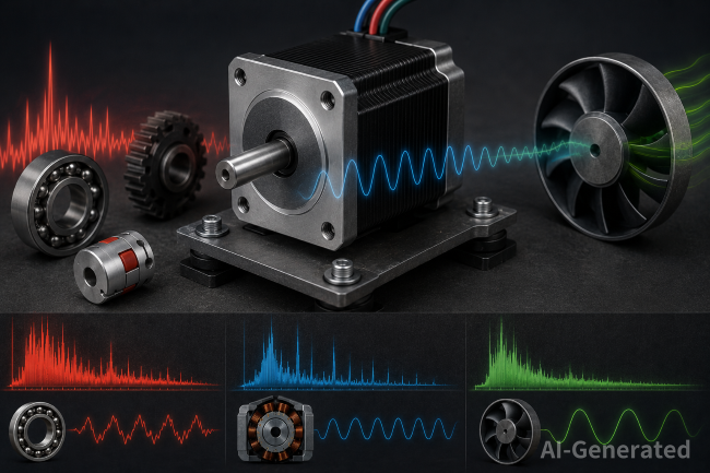
Causes and Mechanisms
Drive Mode Determines Excitation
The control algorithm is the largest controllable variable in stepper motor noise generation.
| Drive Mode | Torque Ripple | Vibration Level | Best Speed Range |
| Full-step | Highest | High | Very low speed |
| Half-step | High | Medium–High | Low speed |
| 1/4–1/8 microstep | Medium | Medium | General purpose |
| 1/16 microstep | Low | Low | Low-to-mid speed |
| 1/64–1/256 microstep | Very low | Very low | Mid-to-high speed Start at 70–90% of rated current |
Current and Resonance
Current setting is frequently overlooked. Overcurrent drives magnetic saturation, increasing vibration and heat. Start at 70–90% of rated current, then tune downward if torque margin allows.
Resonance appears between 50–200 RPM for most hybrid motors. At these speeds, vibration amplitude spikes and the motor may stall even under no load. Load inertia and coupling type determine severity:
- Rigid couplings: Transmit vibration directly; high precision, high noise
- Jaw couplings: Damp high-frequency content; slight backlash
- Bellows couplings: Maintain precision while absorbing minor misalignment
Measurement and Diagnostics
Effective diagnosis of stepper motor noise requires quantification, not guesswork.
| Tool | Measures | Use Case | Accessibility |
| Sound level meter | dB(A) | Overall level, compliance | Low |
| Triaxial accelerometer | g RMS | Vibration magnitude, directionality | Medium |
| FFT analyzer | Frequency spectrum | Tonal vs. broadband separation | Medium–High |
| MEMS IMU | Accel + gyro | Motor-mounted resonance detection | Low |
FFT interpretation rules:
- Step-frequency fundamental: Electromagnetic, drive-related
- Harmonics at integer multiples: Current distortion or PWM artifacts
- Broadband >2 kHz: Bearing wear or gear meshing
- Narrowband at structural frequency: Mounting or frame coupling issue
Diagnostic sequence:
- Run at constant speed in full-step. Note dominant tonal frequency.
- Switch to 1/16 microstepping at same mechanical speed. If tone drops significantly, root cause is drive excitation.
- If high-frequency noise persists across all modes, inspect bearings and alignment.
- Apply light load manually. Noise that changes with load direction indicates coupling or gearbox issues.
Practical Noise Reduction Strategies
Drive Optimization
- Microstepping: Start with 1/16 for low speed. Higher microstepping resolutions may help distribute excitation energy over a broader frequency range and reduce audible tonal components, although results depend on the driver architecture and mechanical system.
- Current tuning: Set to 70% rated current; increase in 5% increments until missed steps disappear; back off 10% for thermal margin.
- Motion profiling: Use S-curve or trapezoidal ramps. Jerk limitation prevents impulse loading that triggers resonance.
Mechanical Improvements
- Vibration isolation: Rubber dampers or elastomer washers between motor face and mounting plate reduce structure-borne transmission by 5–15 dB.
- Fastener discipline: Torque to spec, use thread-locking compound, inspect after 50 hours. Loose hardware converts vibration into panel-radiated stepper motor noise.
- Lubrication: PTFE-impregnated grease for light loads; lithium-complex for moderate loads. Re-lubricate every 500–1000 hours.
Environmental Containment
- Acoustic foam lining absorbs 500 Hz–5 kHz content
- Mass-loaded vinyl barriers block low-frequency rumble
- Sealed cable glands prevent leakage through openings
Implementation example: A desktop CNC mill producing 68 dB(A) during rapids achieved 54 dB(A) through sequential changes: 1/32 microstepping drivers (–6 dB), S-curve firmware (eliminated resonance growl), rubber isolation washers (–4 dB), and 25 mm melamine foam lining (–4 dB).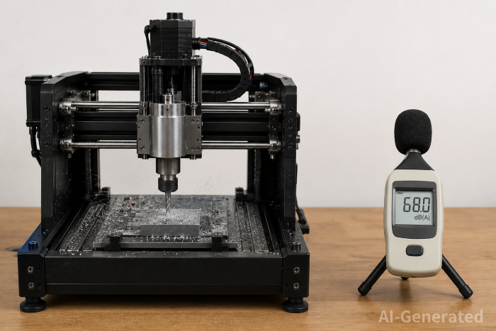
Maintenance and Longevity
Bearing life decreases exponentially with vibration amplitude. Motors running at higher microstepping resolutions experience lower cyclic stress, extending service intervals. Inspect and re-torque mounting hardware every six months in industrial environments.
Resonance avoidance tactics:
- Shift operating speed by 20% or more from resonant band
- Add viscous damper to shaft extension
- Use closed-loop control with encoder feedback
Overload protection: Running above rated torque forces repeated missed-step recovery, producing a distinct "grinding" sound and accelerating wear. Size motors with at least 30% torque margin.
Trend monitoring: Establish baseline vibration signatures at commissioning. Track overall g RMS, step-frequency harmoics, and bearing frequency bands. A 3 dB increase or new spectral peaks indicates degradation before it becomes audible.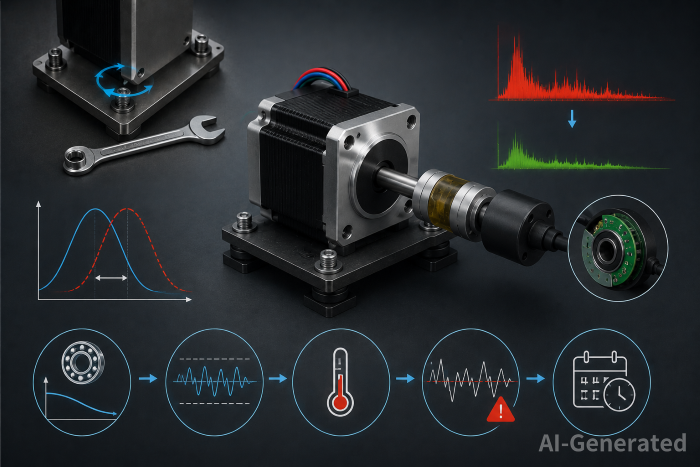
FAQ
Q: Does higher microstepping always reduce stepper motor noise?
A: In most applications, increasing microstepping up to 1/16 significantly reduces vibration and audible noise. Beyond 1/32 or 1/64, the improvement becomes increasingly application-dependent and often provides diminishing returns.
Q: Can stepper motor noise be eliminated entirely?
A: No. Even at 1/256, broadband noise from bearings and air turbulence remains. The goal is to push tonal electromagnetic noise out of the audible band.
Q: Why does my motor get louder at specific speeds?
A: Mechanical resonance, typically 50–200 RPM for hybrid steppers. Avoid continuous operation in that range or add damping.
Q: Cheapest first step to reduce stepper motor noise?
A: Reduce drive current to the minimum reliable level and increase microstepping to 1/16. Zero hardware cost.
Q: Is a noisy stepper motor a sign of failure?
A: Not necessarily. Electromagnetic noise is a normal characteristic of stepper motors. However, grinding, rattling, sudden increases in noise level, or vibration that changes significantly over time may indicate bearing wear, loose mechanical components, or alignment issues that require inspection.
Conclusion
Stepper motor noise is rarely a single-point failure. Electromagnetic excitation from torque ripple interacts with mechanical resonance and mounting dynamics to produce the final acoustic output. Effective control follows a sequence: optimize the drive, match the mechanics, contain what remains, and monitor over time. In most field implementations, moving from full-step to 1/16 microstepping with basic isolation hardware reduces noise by 10–15 dB—enough to move equipment from workshop-tolerable to office-compatible. Measurement is the critical enabler; without FFT-based diagnostics, noise reduction remains guesswork rather than engineering.
Keep Learning
Closed Loop Stepper Motor: How It Works, Benefits, and Applications
Stepper motors have long been a go-to solution for precise positioning in industrial automation. But traditional open-loop stepper systems come with a well-known limitation: they have no way of knowing whether the motor actually reached its commanded position. If steps are lost due to a sudden load change or mechanical jam, the system carries on, unaware of the error. Closed loop stepper motors solve this problem by adding an encoder and a feedback-capable driver to the system. The result is a motor t......
Unipolar vs Bipolar Stepper Motor: Key Differences and How to Choose
You're looking at two NEMA 23 stepper motors with similar torque ratings on paper and a price difference that doesn't quite make sense. One is listed as bipolar, the other unipolar. The datasheet tells you the holding torque, rated current, and step angle, but it doesn't explain why the winding configuration matters — or whether it matters for your application. It does, but not always in the way most comparisons suggest. The performance difference between unipolar and bipolar motors starts with a simp......
Permanent Magnet Stepper Motor: How It Works and How to Choose the Right One
Introduction Permanent magnet stepper motors are widely used in applications such as printers, HVAC actuators, ticket dispensers, and laboratory devices, where reliable incremental motion is more important than ultra-high positioning accuracy. Unlike variable reluctance designs, PM stepper motors use a permanent magnet rotor that interacts directly with stator-generated magnetic fields to produce discrete movement. This design provides useful low-speed torque, straightforward control, and cost-effecti......
NEMA Stepper Motor Sizes, Specifications, and Frame Size Chart Explained
NEMA stepper motor sizes standardize the mechanical interface—faceplate width, bolt pattern, and pilot diameter—but leave torque, thermal behavior, and high-speed performance to the manufacturer's design choices. Conflating frame size with motor capability is a frequent source of integration failure. The following sections detail the exact dimensions of each NEMA frame and explain how to read the specifications that actually determine whether a motor will work in your application. What Does NEMA Mean?......
How to Select a Stepper Motor: Step-by-Step Guide
Introduction Proper stepper motor sizing is essential for achieving reliable positioning performance. Selecting the wrong stepper motor usually shows up as missed steps, excess heat, or stalled motion mid-cycle. The root cause is rarely the motor itself—more often, the selection process skipped load verification or assumed catalog torque ratings apply directly to the application. This guide breaks down a practical sizing workflow. It covers torque calculations, motion profile definition, and the drive......
Optimizing Stepper Motor Speed: Factors, Dynamics, and Control Strategies
Introduction Stepper motor speed optimization is where electrical drive design meets mechanical dynamics. Push too hard without voltage margins, and mid-band resonance stalls the rotor. Run overly conservative profiles on a high-inertia gantry, and cycle times suffer. The real challenge isn't hitting a datasheet RPM—it's maintaining positional accuracy as load, driver, and thermal conditions shift. Understanding stepper motor speed limits, measurement methods, and control strategies is essential for b......