Optimizing Stepper Motor Speed: Factors, Dynamics, and Control Strategies
10 min
- Introduction
- Basic Concepts of Stepper Motor Speed
- Key Factors Affecting Stepper Motor Speed
- Dynamic Characteristics of Speed and Acceleration
- Speed Optimization Through Control Strategies
- Speed Measurement and Tuning Techniques
- FAQ
- Conclusion
Introduction
Stepper motor speed optimization is where electrical drive design meets mechanical dynamics. Push too hard without voltage margins, and mid-band resonance stalls the rotor. Run overly conservative profiles on a high-inertia gantry, and cycle times suffer. The real challenge isn't hitting a datasheet RPM—it's maintaining positional accuracy as load, driver, and thermal conditions shift.
Understanding stepper motor speed limits, measurement methods, and control strategies is essential for building reliable motion systems.
Basic Concepts of Stepper Motor Speed
Step Angle and Steps per Revolution
A 1.8° step angle equals 200 steps per revolution (SPR) in full-step mode. At 2000 steps per second, the shaft turns at 600 RPM. This relationship is linear until electrical and mechanical limits intervene. Microstepping divides full steps into smaller slices (16× or 32×), increasing smoothness without changing the fundamental stepper motor speed ceiling.
Speed Classification
Typical operating ranges for many NEMA 17 and NEMA 23 motors are shown below, although actual limits depend on motor design, voltage, and load conditions.
| Range | Typical RPM | Dominant Concern |
| Low-speed | 0–300 | Resonance, cogging, torque ripple |
| Mid-speed | 300–1000 | Back-EMF rise, current decay lag |
| High-speed | 1000+ | Inductive time constant, torque collapse |
Low-speed errors usually stem from resonance, not load. Mid-speed is the transition zone where winding L/R time constants fight the driver. High-speed stepper motor speed is almost always voltage-limited; the driver cannot force current fast enough against rising back-EMF.
Speed, Torque, and Inertia
Torque drops with speed due to electrical time constants and back-EMF. The pull-out torque curve defines the maximum torque available at a given stepper motor speed without losing synchronism. Acceleration demands torque following T = J × α. A motor holding 1 N·m statically might deliver only 0.3 N·m at 800 RPM. If the load needs 0.35 N·m to reach that stepper motor speed in time, the rotor stalls.
Key Factors Affecting Stepper Motor Speed
Supply Voltage and Current
Voltage is the primary enabler of stepper motor speed. A winding is an inductor; current rise follows I = V/R × (1 - e-t/T). At high speeds, step periods shrink. If supply voltage is too close to the motor's rated voltage, current never reaches target before phase switching.
Practical rule: run the driver at 5–10× the motor's rated voltage for high stepper motor speed. A 2 A, 3 V motor performs better at 24 V than 12 V, assuming the driver handles chopping regulation. Higher voltage allows faster current slew rates, directly improving torque at speed.
Current setting is equally critical. Overshoot the rating, and temperature rises with I2. Undershoot, and torque collapses. A common error is setting peak rated current without checking duty cycle.
Driving Modes
Driving mode changes the electrical signature of each mechanical step:
| Mode | Steps/Rev | Torque Ripple |
| Full-step | 200 | High |
| Half-step | 400 | Moderate |
| Microstep (16×) | 3200 | Very low |
Full-step excites resonance aggressively. Microstepping reduces torque ripple by energizing windings with sinusoidal current ratios. It does not increase absolute torque limits. At high stepper motor speed, the distinction between full-step and 16× narrows because the driver has less time per microstep to regulate current. For most high-speed applications, 8× or 16× is the sweet spot.
Load and Mechanical Resistance
The motor never drives an ideal inertia. Friction, belt tension, lead screw efficiency, and cable drag all consume torque. A ball screw at 90% efficiency demands less continuous torque than an ACME thread at 40%, but the reflected inertia of the screw itself can dominate. In CNC routers and 3D printers, cable drag chains are frequently underestimated—tight bend radii can add enough effective load to push a motor into stall during rapid traverses.
Internal Motor Parameters
Rotor inertia sets the acceleration bound. A high-torque motor with a large rotor often accelerates slower than a lower-torque, lightweight rotor when driving low-inertia loads. The torque-to-inertia ratio (T/J ) predicts acceleration capability better than raw holding torque.
Winding inductance determines current build speed. Low-inductance motors (1–2 mH) suit high stepper motor speed with voltage-limited drivers. High-inductance motors (5–10 mH) work at low speeds but torque drops rapidly above 500–800 RPM.
Dynamic Characteristics of Speed and Acceleration
Acceleration Profiles
Every motion segment has ramp-up, constant speed, and ramp-down phases. Linear (constant acceleration) profiles impose torque steps at boundaries, exciting mechanical resonance. S-curve profiles soften jerk—the rate of change of acceleration—reducing excitation of low-frequency resonant modes.
Typical starting points:
| Application | Starting Acceleration | Notes |
| 3D printer (direct drive) | 1500–3000 mm/s² | Limited by frame rigidity |
| CNC mill (light duty) | 500–1500 mm/s² | Prioritize surface finish |
| Pick-and-place | 3000–8000 mm/s² | Short moves, light heads |
The actual limit is found by increasing acceleration until missed steps occur, then backing off 20–30%.
Resonance Phenomena
Stepper motors have natural resonant frequencies, typically 50–200 Hz for NEMA 17 frames. At these speeds, the rotor oscillates around commanded position, causing rough sound, torque loss, or stall. Microstepping is the first line of defense—it reduces energy injected per step. The most effective electronic solution is closed-loop control with a fast servo loop that detects position deviation and compensates within microseconds.
On open-loop systems, accelerating through the resonant zone quickly often works better than dwelling there. If operation in that band is required, 16× microstepping is effectively mandatory.
High-Speed Constraints
Above 1000 RPM, back-EMF approaches supply voltage, current cannot be driven into windings, iron losses increase, and driver bandwidth limits PWM tracking. The practical stepper motor speed ceiling for most hybrid motors under standard drives is 1500–3000 RPM. Above this, servo or brushless DC motors with encoders are generally the better choice.
Speed Optimization Through Control Strategies
Open-Loop vs. Closed-Loop
Open-loop assumes the rotor follows commanded steps. It works until load transients, resonance, or voltage sag cause missed steps. Closed-loop adds an encoder and adjusts commutation in real time, enabling higher usable torque across the stepper motor speed range and recovery from transient overloads.
| Aspect | Open-Loop | Closed-Loop |
| Position certainty | Assumed | Verified |
| Torque utilization | ~50–70% of holding | Up to 100% of peak |
| Resonance handling | Poor | Actively damped |
| Failure mode | Silent position loss | Detectable fault alarm |
For applications where process interruptions carry significant production costs, closed-loop systems are increasingly being adopted to improve reliability.
Microstepping for Smooth Motion
Microstepping's primary benefit at high stepper motor speed isn't resolution—it's the reduction of current discontinuities between steps. Full-step mode creates hard current transitions and torque ripple. Microstepping spreads the transition across multiple microsteps, smoothing torque vector rotation. At very high speeds, inductance filters out microstepping detail anyway, but the entry and exit from high-speed segments benefit significantly from smoother acceleration ramps.
Trapezoidal vs. S-Curve Profiles
Trapezoidal profiles are computationally cheap but impose jerk at profile corners, exciting structural resonances visible as ringing in 3D prints. S-curve profiles limit jerk, reducing frame excitation and often improving effective settling time. Not all motion controllers support true S-curve planning; modern 32-bit ARM controllers handle the math without issue, while 8-bit controllers may approximate it with segmented linear pieces.
Speed Measurement and Tuning Techniques
Measurement Methods
Encoder feedback is the ground truth. Velocity is derived from position deltas. Resolution should be at least 4× the motor's step resolution to capture microstepping errors.
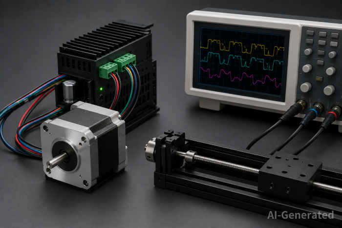
Oscilloscope measurement verifies electrical performance. Probe the driver's step input and one phase current. Compare commanded versus actual step frequency to isolate controller timing issues from motor problems.
Current waveform analysis shows whether the driver achieves target current within each step period. At high stepper motor speed, phase current becomes triangular rather than square. If average current collapses, the supply voltage is insufficient.
Practical Tuning Example
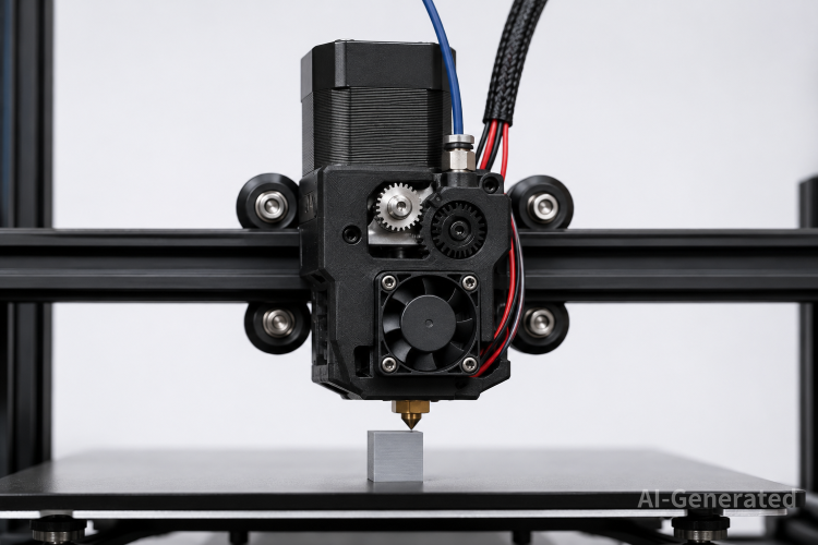
Consider a NEMA 17 direct-drive 3D printer extruder targeting 120 mm/s (roughly 800 RPM):
- Set 16× microstepping, 24 V supply, current at 70% of motor rating.
- Send a high-speed move command. Capture step frequency with a scope to verify it matches calculated steps/mm × speed.
- Start acceleration at 1000 mm/s². Print a test pattern with sharp corners. Listen for skipped steps or check for shifted layers.
- Increase acceleration by 200 mm/s² until artifacts appear, then back off 25%.
- Run a 30-minute continuous print. Check motor temperature with an IR thermometer. If >70°C, reduce current 10% and retest.
On a well-tuned system with a low-inductance motor and 24 V supply, accelerations of 2500–4000 mm/s² are achievable without compromising print quality.
Common Mistakes
| Symptom | Likely Cause | Fix |
| Stalls at 200–400 RPM | Mid-band resonance | Increase microstepping; accelerate through the zone |
| Torque collapse above 800 RPM | Insufficient voltage | Increase supply; select lower inductance motor |
| Overheating after 10 min | Current too high | Reduce to 60–80% of rated |
| Layer shifts | Mechanical binding | Check pulleys and rail alignment |
| Audible whine at specific speeds | Resonance | Change microstepping; add damping |
| Position drift over long runs | Missed steps accumulating | Implement closed-loop; reduce stepper motor speed |
Power supply sag is frequently overlooked. A 24 V supply might droop to 20 V under rapid acceleration when multiple axes demand current simultaneously. The motor needs voltage to recover between steps; poor transient response causes intermittent stalls that look mechanical.
FAQ
Q: Does increasing microstepping always improve accuracy?
A: No. Beyond 16× or 32×, mechanical system compliance usually dominates error. Electrical microstepping precision beyond mechanical resolution is wasted.
Q: Can I run a 12 V rated motor on 48 V?
A: Yes, with a current-limited chopper driver. Higher voltage improves high stepper motor speed performance. Ensure the driver's voltage rating exceeds 48 V.
Q: Why does my motor get louder at specific speeds?
A: Resonance. The step rate matches a natural frequency of the rotor-load system. Change acceleration, microstepping ratio, or add damping.
Q: Is closed-loop necessary for a 3D printer?
A: Not strictly, but it significantly reduces failed prints due to collisions or jams causing missed steps. The cost has dropped enough to make it sensible for production machines.
Q: How do I know if my power supply is the bottleneck?
A: Scope the supply rail during rapid direction changes. If droops exceed 10%, add bulk capacitance near the driver or upgrade the supply.
Conclusion
Stepper motor speed optimization is a system-level problem. The datasheet torque curve is only the starting point. Supply voltage, driver current control quality, acceleration profile shape, and load inertia collectively determine the real speed ceiling.
A low-inductance motor on 24 V with 16× microstepping and an S-curve profile will often outperform a higher-torque motor on 12 V with full-step control. The difference is in electrical dynamics: current rise time, back-EMF headroom, and resonance avoidance.
For engineers building motion systems, the actionable takeaway is to measure rather than assume. Scope phase current. Log encoder position error during acceleration. Test the supply under worst-case simultaneous axis load. Stepper motor speed is not just about how fast the rotor spins; it is about maintaining commanded position while it does.
Keep Learning
Closed Loop Stepper Motor: How It Works, Benefits, and Applications
Stepper motors have long been a go-to solution for precise positioning in industrial automation. But traditional open-loop stepper systems come with a well-known limitation: they have no way of knowing whether the motor actually reached its commanded position. If steps are lost due to a sudden load change or mechanical jam, the system carries on, unaware of the error. Closed loop stepper motors solve this problem by adding an encoder and a feedback-capable driver to the system. The result is a motor t......
Unipolar vs Bipolar Stepper Motor: Key Differences and How to Choose
You're looking at two NEMA 23 stepper motors with similar torque ratings on paper and a price difference that doesn't quite make sense. One is listed as bipolar, the other unipolar. The datasheet tells you the holding torque, rated current, and step angle, but it doesn't explain why the winding configuration matters — or whether it matters for your application. It does, but not always in the way most comparisons suggest. The performance difference between unipolar and bipolar motors starts with a simp......
Permanent Magnet Stepper Motor: How It Works and How to Choose the Right One
Introduction Permanent magnet stepper motors are widely used in applications such as printers, HVAC actuators, ticket dispensers, and laboratory devices, where reliable incremental motion is more important than ultra-high positioning accuracy. Unlike variable reluctance designs, PM stepper motors use a permanent magnet rotor that interacts directly with stator-generated magnetic fields to produce discrete movement. This design provides useful low-speed torque, straightforward control, and cost-effecti......
NEMA Stepper Motor Sizes, Specifications, and Frame Size Chart Explained
NEMA stepper motor sizes standardize the mechanical interface—faceplate width, bolt pattern, and pilot diameter—but leave torque, thermal behavior, and high-speed performance to the manufacturer's design choices. Conflating frame size with motor capability is a frequent source of integration failure. The following sections detail the exact dimensions of each NEMA frame and explain how to read the specifications that actually determine whether a motor will work in your application. What Does NEMA Mean?......
How to Select a Stepper Motor: Step-by-Step Guide
Introduction Proper stepper motor sizing is essential for achieving reliable positioning performance. Selecting the wrong stepper motor usually shows up as missed steps, excess heat, or stalled motion mid-cycle. The root cause is rarely the motor itself—more often, the selection process skipped load verification or assumed catalog torque ratings apply directly to the application. This guide breaks down a practical sizing workflow. It covers torque calculations, motion profile definition, and the drive......
Optimizing Stepper Motor Speed: Factors, Dynamics, and Control Strategies
Introduction Stepper motor speed optimization is where electrical drive design meets mechanical dynamics. Push too hard without voltage margins, and mid-band resonance stalls the rotor. Run overly conservative profiles on a high-inertia gantry, and cycle times suffer. The real challenge isn't hitting a datasheet RPM—it's maintaining positional accuracy as load, driver, and thermal conditions shift. Understanding stepper motor speed limits, measurement methods, and control strategies is essential for b......