Why Does Your Stepper Motor Always Make a Squealing Noise?
6 min
- Key Causes of Stepper Motor Squealing
- Step-by-Step Guide to Resolving Stepper Motor Squeaking
- Proactive Design & Component Selection
- Frequently Asked Questions
- Conclusion
A squealing stepper motor is almost never a mechanical grinding issue. The noise is electrical: PWM chopping, magnetic resonance, or current misconfiguration exciting the stator laminations. This article provides a four-step workflow to isolate the root cause and fix it without losing torque or steps.
Key Causes of Stepper Motor Squealing
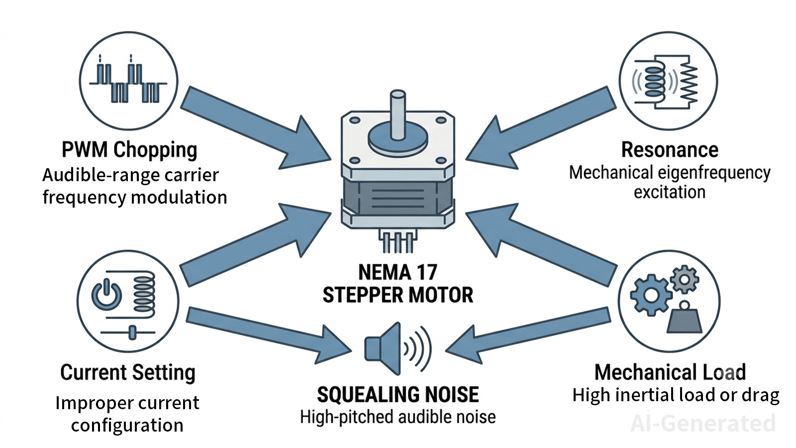
1. PWM Chopping Frequency in the Audible Range
Motor drivers control current by rapidly switching MOSFETs. If the chopping frequency sits below 20 kHz, each switching transient flexes the stator core at an audible rate. The motor effectively becomes a magnetic loudspeaker.
| Chopping Frequency | Audible Effect |
| < 10 kHz | Loud squeal or whine |
| 10–20 kHz | High-pitched tone, still audible |
| > 20 kHz | Generally inaudible |
Fix: Raise the chopping frequency or switch to a driver that operates above 20 kHz by default.
2. Natural Resonance Excitation
A stepper motor is a spring-mass system. When the step pulse frequency crosses the rotor-stator resonant band—typically 50–200 Hz for NEMA 17/23 motors—the rotor oscillates violently. This produces a high-pitched rattle, severe torque drop, and potential step loss.
Resonance is a physics boundary, not a defect. It appears most often during low-to-mid RPM acceleration when the step rate traverses that band.
3. Incorrect Current and Magnetic Saturation
Setting V_ref or firmware current too high provides little additional torque while significantly increasing heat generation and high-frequency noise. Setting it too low prevents stable rotor lock during hold states, causing electromagnetic jitter and buzzing.
Rule of thumb: A common starting point is 70%–100% of the rated RMS current, depending on the driver, cooling conditions, and required torque.
4. Mechanical Binding or Bearing Failure
Misaligned lead screws, over-tensioned belts, or worn bearings impose asymmetrical loads. These force the rotor off its magnetic centerline, amplifying baseline electromagnetic noise through mechanical strain.
| Symptom | Likely Cause |
| Squeal changes pitch under load | Mechanical binding or resonance |
| Squeal at standstill, constant pitch | Electrical chopping or current dither |
| Rough vibration alongside noise | Bearing failure or bent shaft |
| Noise only on direction reversal | Backlash or loose coupler |
Step-by-Step Guide to Resolving Stepper Motor Squeaking
Step 1: Optimize Microstepping
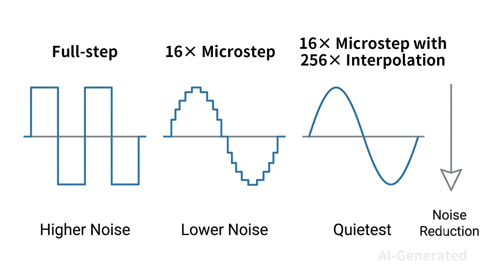
Full-step and half-step modes deliver current in sharp rectangular pulses that shock the stator into ringing. Upgrading to 16× microstepping or higher smooths the waveform into a near-sinusoidal shape, eliminating the transients that cause squeals.
| Mode | Waveform | Noise Level |
| Full-step | Square | Loud squeal |
| 16× microstep | Near-sinusoidal | Significantly quieter |
| 256× interpolation | Smooth sine | Inaudible in most cases |
The incremental torque reduction at 16× is negligible for most positioning applications.
Step 2: Tune Chopper Modes
Modern Trinamic drivers (TMC2209, TMC5160) offer configurable modes:
- StealthChop: Voltage-mode PWM with automatic frequency optimization. Best for low-to-mid speed where silence matters.
- SpreadCycle: Cycle-by-cycle current regulation. Slightly more audible at low speed but superior torque ripple control during rapid acceleration.
Klipper example:
[tmc2209 stepper_x]
uart_pin: PA3
run_current: 0.800
hold_current: 0.500
stealthchop_threshold: 999999
A high threshold forces StealthChop across the full velocity range. For high-speed torque demands, use a lower threshold for automatic SpreadCycle transition.
Step 3: Calibrate Current Accurately
- Read the rated RMS current from the motor datasheet.
- Set target to 75% of rated value.
- Convert to V_ref for potentiometer drivers, or set "run_current" directly in firmware for UART/SPI drivers.
- Verify thermally: motor casing should stay below 60–70°C after 30 minutes.
Step 4: Decouple the Load
Remove the shaft coupler or belt and run the motor unloaded.
- Squeal disappears: Problem is mechanical. Inspect alignment, bearings, and tension.
- Squeal persists: Problem is electrical. No amount of mechanical tuning will fix it.
Proactive Design & Component Selection
Closed-Loop Systems
Closed-loop steppers with integrated encoders actively dampen resonance by adjusting the field vector in real time. Specifying closed-loop hardware at the BOM stage eliminates retrofit debugging for noise-sensitive applications.
Hardware-Level Noise Suppression
Driver optimization can only suppress what the motor generates. Motors with poor lamination quality or loose bearings will squeal regardless of chopper tuning.
JLCMC's premium stepper lineup addresses this at the source:
- Optimized magnetic circuits reduce cogging torque and harmonic distortion.
- Low-loss silicon steel laminations minimize eddy-current losses and electromagnetic vibration during PWM operation.
- Precision-matched bearings maintain rotor centering under dynamic load without introducing excess friction.
These are measurable mechanical properties, not catalog marketing points. A motor built with tight lamination tolerances and pre-loaded bearings provides the physical foundation that makes silent driver configurations actually achievable.
Frequently Asked Questions
Q1: Why does the motor squeal only when holding position?
Holding current set too high causes mild saturation with no motion to dissipate heat, making chopping cycles audible. Set "hold_current" to 50%–70% of "run_current" and verify the decay mode minimizes standstill current ripple.
Q2: Will the noise burn out the motor?
The squeal itself does not destroy windings, but the underlying conditions—resonance, saturation, excess heat—accelerate bearing degradation and insulation aging. The more immediate risk is positional inaccuracy from inconsistent torque delivery.
Q3: Can I fix this by just swapping the motor?
Rarely. Two NEMA 17 motors can have vastly different inductance and resistance. A driver tuned for one motor will likely misdrive a replacement. Isolate the problem electrically first, match the driver to the new motor's datasheet, then assess physical construction.
Q4: Does higher microstepping reduce usable torque?
It reduces incremental torque per microstep, not holding torque. In practice, 16× microstepping provides the optimal balance: dramatic noise reduction with sufficient torque for typical 3D printer and CNC loads. 256× offers diminishing acoustic returns while increasing controller bandwidth demands.
Conclusion
A squealing stepper is a diagnostic signal with specific, quantifiable causes: audible-range PWM chopping, resonance excitation, magnetic saturation, or mechanically amplified binding. Fix it by isolating the load, calibrating current to 75% of rated value, upgrading to 16× microstepping, and configuring chopper modes above 20 kHz. Treat the motor, driver, and mechanics as one integrated system—not separate domains. Specifying hardware built for low-noise operation from the start eliminates the debugging entirely.
Keep Learning
Ball Screw Types Explained: Features, Differences & Applications
You need accurate motion control for your industrial equipment. A ball screw changes rotary drive into linear movement with high efficiency. You will find many ball screw types across modern hardware shops today. Each design serves a specific role in your setup. This guide helps you pick the best model for your next project. Key Takeaways People select specific models based on simple mechanics. Production methods affect the accuracy level of the screw shaft. Nut designs control how steel balls circula......
Why Does Your Stepper Motor Always Make a Squealing Noise?
A squealing stepper motor is almost never a mechanical grinding issue. The noise is electrical: PWM chopping, magnetic resonance, or current misconfiguration exciting the stator laminations. This article provides a four-step workflow to isolate the root cause and fix it without losing torque or steps. Key Causes of Stepper Motor Squealing 1. PWM Chopping Frequency in the Audible Range Motor drivers control current by rapidly switching MOSFETs. If the chopping frequency sits below 20 kHz, each switchin......
Linear Guide Rails and Bearings: What's the Difference and Which Should You Use?
Pick any machine that moves in a straight line — a CNC router, a pick-and-place unit, a 3D printer gantry — and somewhere inside it you will find either a linear bearing riding on a round shaft or a linear guide rail carrying a carriage block. Although they are sometimes discussed interchangeably, round-shaft linear bearings and profiled linear guide rails are two different linear motion systems designed for different levels of precision, rigidity, and load capacity. Both deliver low-friction, guided,......
What Actually Goes Into a Linear Guide Rail System
A linear guide rail system is more than one rail. On its own, the rail cannot provide guided motion. What supports the load and maintains positioning accuracy is how the rail, carriage, rolling elements, and seals work together. This is a quick tour of those parts, and how they add up to a complete motion axis. For engineers speccing a new axis and buyers matching a system to a machine. If you just need the basics — what a linear guide is or the different types of linear rails — start with those two g......
What Are Linear Guides and Why Do They Matter in Factory Automation?
Every CNC machine, every pick-and-place robot, every wafer handler on a semiconductor line — they all share one fundamental need: moving something in a straight line, accurately and repeatedly. That's where linear guides come in. Despite being one of the most widely used components in factory automation, linear guides are often misunderstood — partly because the industry can't agree on what to call them. This article breaks down what linear guides actually are, what's inside them, the main types of li......
Exploring Mechanical Shaft Collars and Their Different Types
Though quite elementary in design, shaft collars serve an important mechanical purpose. In simple terms, a shaft collar is a round clamping device that can be used for axial positioning of components, acting as mechanical stops, or securing parts in place along a shaft. While they may look like simple components, shaft collars must be chosen wisely to ensure performance, accuracy, and longevity of the system. This article focuses on the common types of mechanical shaft collars in transmission systems,......