Gear Pitch Explained: How Pitch Diameter Affects Gear Design
7 min
- Introduction
- Determination of Core Design Dimension: Gear Pitch Diameter
- The Two Systems Circular Pitch and Diametral Pitch Gear
- Significance of Gear Pitch in Matching of Components
- Conversion and Interaction with Gear Module
- Example Applications of Gear Pitch in Design
- Conclusion
- FAQs
Introduction
In any gear system, the size, spacing, and meshing of the teeth all impact the efficiency of power transmission. Pitch is one of the key parameters influencing these factors. The spacing between the teeth around the gear is determined by the pitch, which directly affects whether two gears can mesh correctly.
The pitch circle diameter is a key dimension in gear definition. It represents a theoretical circle around which all meshing tooth surfaces engage and roll. Pitch not only affects the precision of gear meshing but also determines the distribution of the gear toothing and the contact pattern. A precise pitch ensures even gear tooth distribution, optimizing gear performance and power transmission efficiency. As mentioned, without a matching pitch, even the best mechanical gears cannot work together effectively.
Determination of Core Design Dimension: Gear Pitch Diameter
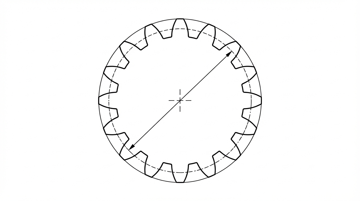
The pitch diameter of a gear is an imaginary circle on which two gears are presumed to be rolling without any slippage. This circle itself is not an actual thing that's visible on the gear, but it is the most significant point to consider when performing calculations for gears.
The gear teeth roll at the pitch circle without any sliding taking place. Thus, it serves as a reference for gauging tooth distance, gear step, and speed ratios. Almost all the values of gear sizes, such as addendum, dedendum, and tooth thickness, are based on the pitch circle.
Simply put, pitch diameter is the "working size" of your gear. The OD or tooth form may be different, but it's the pitch diameter that decides how a gear is going to play with others.
Pitch Diametral and Center Distance Relationship
The pitch circles of the two gears in mesh tangentially touch each other at a single point. The complementary distance between the axes of two gears, called center distance, is also dependent on pitch diameters.
The center distance of two meshing gears is equal to half the sum of their pitch diameters. Gears mesh adapt; if the meshing distance error is too large, they are unable to match or may suffer excessive tooth bearing, noise, and wear. This is why gear pitch diameter design is so important during system layout and assembly.
The Two Systems Circular Pitch and Diametral Pitch Gear
Circular Pitch Gear: The Metric and Tangential System of Measurement
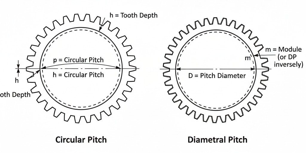
The circular pitch (Pₙ) is the distance between corresponding points of adjacent teeth, measured along the arc at the pitch circle. It is the arc length of one tooth plus one space.
It is widely used in metric-based gear systems and is closely related to the gear module. It indicates the manner in which teeth are spaced around the pitch circle and is natural in connection with tooth geometry.
Circular pitch is simply the length of the arc along a single tooth measured on the pitch circle. It gives an excellent representation of tooth spacing and, when tangential dimensions are important, can be used to develop precise profiles.
Diametral Pitch Gear System Explained
The diametral pitch gear system (Pₑ) is common to inch-based standards. Diametral pitch is the number of teeth per inch of diameter at the gear's pitch circle.
That is to say, it indicates how many teeth fit into a pitch diameter. The greater the diametral pitch, the more teeth are contained in a given diameter, resulting in smaller and finer teeth. Lower diametral pitch equals fewer teeth and bigger, stronger teeth.
There is a reciprocal system between the metric module and diametral pitch. The module is a direct description of tooth size, while the diametral pitch specifically describes how closely spaced the teeth are.
Significance of Gear Pitch in Matching of Components
The Golden Rule of Gearing
There is one ironclad rule when it comes to designing gears: for two gears to mesh, they must be of the same pitch. This applies to systems using circular, diametral, or module pitch.
The teeth on gears do not align if the pitch is wrong, which results in interference, noise, rapid wear, or total breakdown. Even the slightest disparity in pitch can prevent gears from meshing properly.
This is why gear pitch is usually the first thing engineers look at when designing gears into a new system or replacing gears in an existing one.
Derivation of the Number of Teeth from the Pitch Diameter
The gear number of teeth is a function depending only on gear pitch. In the diametral pitch system, the number of teeth is determined by multiplying the pitch diameter by the diametral pitch.
In the metric system, the number of teeth is determined by dividing the pitch diameter by the module. These relationships enable designers to optimize gear ratios, sizes, and speed relationships.
By setting pitch diameter and pitch system values, designers can cut gears that perform as desired without trial and error.
Conversion and Interaction with Gear Module
In worldwide machine making, both US and SI gear design systems are used. They require conversion in order to work together.
The formula expressing the relationship between diametral pitch and module is:
m = 25.4 / Pₑ
This equation converts the number of teeth per inch (diametral pitch) into module. Understanding this conversion enables engineers to transition designs between standards while maintaining correct tooth form.
Relation Between Gear Pitch, Tooth Size, and Strength
The size and load capacity of a gear tooth are directly affected by gear pitch. A higher value of diametral pitch results in smaller teeth. Smaller teeth provide smoother operation and higher resolution but carry lighter loads.
Conversely, smaller diametral pitch produces larger, thicker teeth that can accommodate greater torque and shock loads. This inverse relationship is a key factor when balancing strength and accuracy in gear design.
Example Applications of Gear Pitch in Design
The right gear pitch is highly application dependent. High-speed, low-load systems such as instruments or timing devices typically use fine-pitch gears with small teeth to achieve smooth and quiet operation.
For heavy-load applications such as industrial machinery or automotive drivetrains, gears are typically designed with larger, coarse-pitch teeth. These sacrifices smoothness for durability and load capacity. Optimal gear pitches are selected to minimize mechanical losses while maintaining performance and durability.
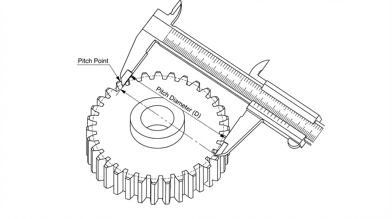
Checking Gear Pitch Diameter
It is crucial to verify pitch diameter during gear production and testing. This is usually performed with specialized measuring machines, such as gear measuring centers, pitch diameter gauges, and analytical inspection units.
Accurate verification ensures that gears meet design requirements and mesh correctly in service. Even minor pitch diameter errors can produce compounded effects in assembled gear trains.
Conclusion
Gear pitch and module are the basic dimensional parameters that determine gear size and tooth spacing. The central reference in this concept is the gear pitch diameter, which governs how gears mesh, transmit motion, and carry loads.
JLCMC provides a diverse range of module gears, ensuring a precise fit from pitch circle to tooth profile. Explore our platform to source standardized components built for superior load capacity and seamless mesh.
FAQs
What is the difference between pitch and lead in gears?
Pitch describes the spacing of teeth around the pitch circle, while lead describes the axial distance a tooth advances in one revolution in helical or worm gears. They are related but apply to different aspects of gear geometry.
What is the impact of manufacturing errors on pitch diameter?
Manufacturing variations in pitch diameter can result in uneven tooth contact, noise, and accelerated wear. Precision machining and inspection help reduce these effects.
When will circular pitch be chosen over diametral pitch?
Circular pitch is generally used in metric-based systems where direct measurement of tooth spacing is preferred, while diametral pitch is more common in inch-based gear designs.
Keep Learning
Closed Loop Stepper Motor: How It Works, Benefits, and Applications
Stepper motors have long been a go-to solution for precise positioning in industrial automation. But traditional open-loop stepper systems come with a well-known limitation: they have no way of knowing whether the motor actually reached its commanded position. If steps are lost due to a sudden load change or mechanical jam, the system carries on, unaware of the error. Closed loop stepper motors solve this problem by adding an encoder and a feedback-capable driver to the system. The result is a motor t......
Unipolar vs Bipolar Stepper Motor: Key Differences and How to Choose
You're looking at two NEMA 23 stepper motors with similar torque ratings on paper and a price difference that doesn't quite make sense. One is listed as bipolar, the other unipolar. The datasheet tells you the holding torque, rated current, and step angle, but it doesn't explain why the winding configuration matters — or whether it matters for your application. It does, but not always in the way most comparisons suggest. The performance difference between unipolar and bipolar motors starts with a simp......
Permanent Magnet Stepper Motor: How It Works and How to Choose the Right One
Introduction Permanent magnet stepper motors are widely used in applications such as printers, HVAC actuators, ticket dispensers, and laboratory devices, where reliable incremental motion is more important than ultra-high positioning accuracy. Unlike variable reluctance designs, PM stepper motors use a permanent magnet rotor that interacts directly with stator-generated magnetic fields to produce discrete movement. This design provides useful low-speed torque, straightforward control, and cost-effecti......
NEMA Stepper Motor Sizes, Specifications, and Frame Size Chart Explained
NEMA stepper motor sizes standardize the mechanical interface—faceplate width, bolt pattern, and pilot diameter—but leave torque, thermal behavior, and high-speed performance to the manufacturer's design choices. Conflating frame size with motor capability is a frequent source of integration failure. The following sections detail the exact dimensions of each NEMA frame and explain how to read the specifications that actually determine whether a motor will work in your application. What Does NEMA Mean?......
How to Select a Stepper Motor: Step-by-Step Guide
Introduction Proper stepper motor sizing is essential for achieving reliable positioning performance. Selecting the wrong stepper motor usually shows up as missed steps, excess heat, or stalled motion mid-cycle. The root cause is rarely the motor itself—more often, the selection process skipped load verification or assumed catalog torque ratings apply directly to the application. This guide breaks down a practical sizing workflow. It covers torque calculations, motion profile definition, and the drive......
Optimizing Stepper Motor Speed: Factors, Dynamics, and Control Strategies
Introduction Stepper motor speed optimization is where electrical drive design meets mechanical dynamics. Push too hard without voltage margins, and mid-band resonance stalls the rotor. Run overly conservative profiles on a high-inertia gantry, and cycle times suffer. The real challenge isn't hitting a datasheet RPM—it's maintaining positional accuracy as load, driver, and thermal conditions shift. Understanding stepper motor speed limits, measurement methods, and control strategies is essential for b......