Gear Module: Exploring Its Meaning and Function in Gears
7 min
- Introduction
- Defining the Core Parameter: What is a Gear Module?
- Effect of Gear Module Parameters on the Tooth Forms
- Standardization and Interchangeability
- Considerations of Load, Velocity, and Material Recruitment
- Wrap Up!
- FAQs
Introduction
The gear module is a fundamental metric for determining tooth size and profile geometry. In the world of gear design, while the module is the primary standard for metric systems, it is intrinsically linked to gear pitch—another critical measure of tooth spacing. While many auxiliary parameters can be adjusted independently, the module remains the decisive factor that ensures compatibility between mating gears in any practical application.
In engineering practice, the module dictates part interchangeability, load-carrying capacity, and the overall footprint of the gear train. Regardless of manufacturing precision, an incorrect module selection will compromise mesh integrity and lead to structural failure under design loads. This article provides a clear definition of gear module components and examines why it remains a critical design parameter, influencing everything from mechanical strength and geometry to production efficiency and long-term reliability.
For readers unfamiliar with different gear measurement systems, our article "[What Is Gear Pitch?]" provides helpful context and complements the concept of gear module.
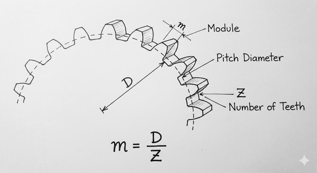
Defining the Core Parameter: What is a Gear Module?
To Construct the Module of a Gear
The gear module is a metric unit that defines the size of the gears' teeth. It is mathematically expressed as:
Module (m) = Pitch Diameter (D) / Number of Teeth (Z)
The module is a measure of gear size, which, because these gears are directly related to each other, means that it links the overall sizes of gears with their tooth counts. The larger the module, the bigger the teeth, and vice versa.
The gear module is all standard, so that there is no difference in the tooth form. Two gears with the same module and pressure angle will mesh properly. This standardization means module gear systems are interchangeable and dependable wherever in the world you may be.
Metric vs. Diametral Pitch (DP)
The metric gear system and module are the unit of size. Imperial gear system, power up transmission applied from this will be Diametral Pitch (DP). It is the number of teeth per inch of pitch diameter, which makes it reciprocal to module size.
More concretely, a small module corresponds to a large Diametral Pitch and vice versa. Conversion from one to the other is achievable, but gears of both systems cannot be combined with each other, and metric module gears should not mesh with DP gears without conversion.
Present-day worldwide production is immensely in favor of module gear trains, as this system complies with ISO and DIN standards protocols, which streamlines the globalization process.
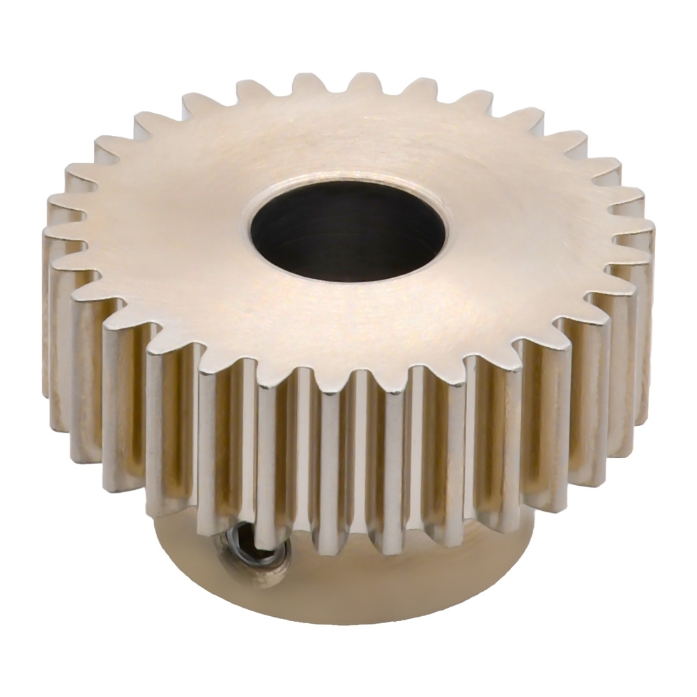
Effect of Gear Module Parameters on the Tooth Forms
Tooth Size and Strength Determination by Module
The gear module has the most direct influence on tooth size. With an increase in module, the tooth thickens, deepens, and becomes mechanically more powerful. This greater capacity permits the gear to accept higher loads or increased tooth pinion sizes.
Conversely, a small gear module makes smaller and more precise teeth suitable for fine mechanics, but with less load-bearing capacity. This is why heavy machinery works with big modules, whereas instruments and actuators use small ones.
In other words, module order is a trade-off between compactness and strength. The right module of a gear allows the teeth to resist the transmitted torque without exhibiting wear or breaking.
Pitch Circle Diameter and Center Distance Affected by the Module
As soon as the module is chosen, it immediately sets or selects the pitch circle of the gear. Notice that because pitch diameter is module times teeth, any change in module scales the whole gear.
This also applies to the central distance of gears engaging each other. When the number of teeth is constant, going to a higher module requires a larger center distance. Therefore, the choice of module doesn't just affect the gears of a mechanical structure; it determines its overall architecture too.
Consequently, designers must consider space restrictions from the outset, as to change module at a later stage often necessitates redesign of shafts, housings, and bearings.
Standardization and Interchangeability
Why the Match Module Is Important for Gear Integration
To engage properly, two gears must have the same module of a gear. Even a small module error will result in improper teeth meshing and noise, vibration, wear, and part failure.
The matching module makes certain that the tooth space and tooth profile of one gear rotate exactly into synchronism with the carrying gear. This is the case regardless of whether a spur, helical, bevel, or internal gear is used.
Thanks to this hard rule, the module parameter is a no-compromising factor in gear matching or substitution.
Modules Conforming to Standards (ISO, DIN)
This is a standardized value of a module, as specified by international standards such as ISO and DIN. These series provide the convenience of choosing frequently used sizes instead of specifying custom dimensions.
The use of standard module gears enables universal replacement, simplifying the supply process and reducing costs. It also allows replacement gears to be secured fast with no redesign of the mating parts.
Considerations of Load, Velocity, and Material Recruitment
Gear Module Selection on the Basis of Torque
Torque section is one of the important factors in designing a gear module. The torque that is transmitted is proportional to the forces on the teeth of the gear, which increase with a higher transmitted load. Therefore, a larger module is required to maintain equivalent strength and surface durability.
As a general rule of thumb, engineers calculate the torque and power needs first, and then make an initial choice with respect to the module based on what will give enough face width and root strength. Final checks are performed by stress and contact calculations.
If a too small module is selected, tooth bending or surface pitting could occur; if a too big module is adopted, the system will be oversized and overweight, making it costly.
On the Interaction Between Material Strength and Choice of Modules
The selection of the module interacts with material choice in a strong manner. High tensile materials, such as case hardening and alloy steels, can transmit more load with a smaller modulus than softer materials, such as cast iron and plastics.
This sets up a trade-off, where stronger materials allow the gear module to be smaller for a given load-carrying capacity and may reduce the overall assembly footprint while maintaining required torque density and structural integrity. Designers need to balance material properties with module size for an optimal solution.
Wrap Up!
The gear module is far more than a theoretical value; it is the definitive sizing tool that establishes the mathematical relationship between pitch diameter and tooth count; it is essential in the design and application of gears. The module determines the size, strength, pitch diameter, and center distance of the gear. A comprehensive mastery of gear modules is indispensable for engineers and technical procurement specialists alike to ensure system-wide compatibility.
If you are ready to apply the theoretical knowledge of gear modules to your projects and are looking for the right high-quality gears, we invite you to visit JLCMC, where we offer a wide range of precision gears to meet various application needs.
FAQs
How to Convert Module Value to Diametral Pitch?
To convert module value to diametral pitch, use the formula: Diametral Pitch (P) = 25.4 / Module (m), where 25.4 is the conversion factor from millimeters to inches.
How Can I Test the Module of Gear?
The module of a gear may be found by measuring the pitch diameter and dividing it by the tooth count.
Is There a Minimum Number of Teeth per Module?
Yes. For normal pressure angles, there is a minimum number of teeth to prevent undercutting, and this limit is influenced by both module and gear type.
Keep Learning
How to Choose a Shaft Coupling: Rigid vs Beam vs Jaw vs Universal Joint
Key Takeaways Shaft Coupling Basics: A shaft coupling transmits torque between driving and driven shafts while accommodating misalignment, vibration, and thermal expansion. The core choice is between rigid (zero flexibility, maximum torque density) and flexible (misalignment-tolerant, vibration-damping) designs. Four Primary Types: Rigid couplings offer zero backlash but require perfect alignment; helical beam couplings provide precision motion for light-duty drives; jaw couplings deliver versatile vi......
Roller Chain Size Chart: ANSI and BS Sizes in mm and Inches
Key Takeaways Identify the chain series first: ANSI and BS-series size codes belong to different dimensional families; changing the units does not change the chain type. Check four details together: Pitch, roller diameter, inner width and number of rows. Matching pitch alone is not enough to choose a replacement. Use the millimeter columns for comparison: Inch equivalents appear beside them, so there is no need to interpret two units in one cell. Count the gaps when measuring pitch: Six consecutive pi......
How to Choose Between Closed-Loop and Open-Loop Stepper Motors
People need the right motor for machine projects. Picking between a closed-loop and open-loop stepper motor shapes machine accuracy and total cost. You can build simple 3D printers with open-loop drives. You can run fast industrial equipment with closed-loop systems. This guide helps you pick the correct motor for your build. Key Takeaways Open-loop stepper systems operate without position feedback, while closed-loop systems use an encoder to monitor actual shaft position. Open-loop systems cannot det......
What Are Pillow Block Bearings? Definition, Working Principle & Applications
Key Takeaways A pillow block bearing is a self-contained bearing unit that combines a rolling-element bearing insert with a rigid housing, designed for shaft support on a flat mounting surface with the shaft axis parallel to the mounting plane. The housing provides structural alignment and load distribution, while the bearing insert handles radial and limited axial loads. Common locking mechanisms include set screws, eccentric collars, and adapter sleeves; each suits different shaft tolerances, vibrat......
Main Types of Servo Motors: AC, DC, and Everything in Between
1. Introduction By leveraging closed-loop feedback to precisely control position, velocity, and torque, servo motors serve as the backbone of modern automation. Yet, application success hinges on matching the right architecture to your load requirements—a task made challenging by the sheer variety of servo motor types available today. In this article, we map motor technology to application requirements through a practical taxonomy covering electrical topology, mechanical construction, performance spec......
Quiet Servo Motors: How to Select Low-Noise Servo Motors for Precision Automation
Noise has quietly become a specification. Medical device makers, semiconductor equipment builders, and packaging OEMs now arrive at the design review with a dB(A) target alongside torque and settling time — and the motion axis is usually the first thing they point at. This guide is written for engineers and buyers specifying industrial AC and brushless servo systems, covering small to medium power ranges commonly used in precision automation equipment. It is not about RC hobby servos: the plastic-gear......