Gear Backlash Causes, Effects, and Control in Gear Systems
7 min
- Introduction
- Defining and Measuring Gear Backlash
- Necessity & Purpose of Gear Backlash
- The Adverse Effects of Over- or Under-Backlash
- Methods to Control and Adjust Backlash
- Conclusion
- FAQs
Introduction
In mechanical power transmission, it is standard practice for gears to mesh with a specific amount of clearance. It is this small, intentionally designed gap that allows the gear system to operate smoothly. This movement difference is referred to as backlash in gears. In simple terms, backlash refers to the gap between meshing gear teeth, allowing the gears to rotate without jamming.
Although backlash is defined during assembly, its physical basis lies in the thickness of each tooth on a gear. By precisely controlling the geometric dimensions of the gear teeth, space for ideal backlash can be allocated from the outset. Without backlash, gears would be unable to rotate, especially under varying loads or temperature conditions. This raises a fundamental question that concerns many engineers, technicians, and students: What is backlash in gears? How does it affect system performance?
Defining and Measuring Gear Backlash
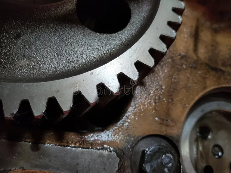
Technically, backlash is the measure of how much wider a tooth space is than the thickness of the engaging tooth on the pitch circles of two meshed gears. In other words, it is the free travel that a cog can execute before setting into motion, thus turning the other.
Squeeze one against the other slightly and rock them back and forth gently – backlash is the amount you can feel them move before feeling resistance. When the gear teeth do not stay in constant mesh with one another, this movement occurs. That clearance allows for trouble-free operation and doesn’t stress the gear teeth under normal field use.
Measurement and Specification Methods of Gear Backlash
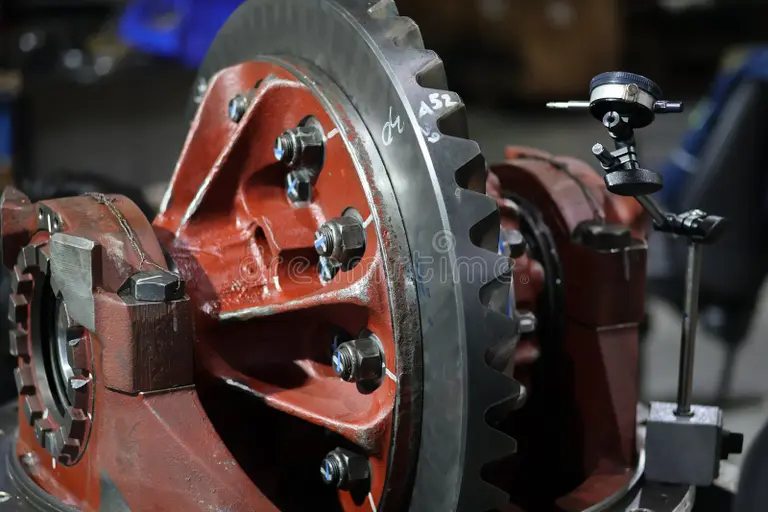
Backlash can be checked either by a variety of standard methods, depending on the desired accuracy and instrumentation type. One of the more popular methods is to employ a dial indicator. The measurement is that of a gear rotating when the mating gear is fixed. The play is the animation on the dial you see.
Another approach is the use of feeler gauges, in which thin metal blades are placed between gear teeth to determine an estimate of clearance. This method is less accurate, but it is enough for maintenance and inspection purposes.
Backlash isn't defined as a single value in design and manufacture. This permits marginal differences due to machining variances, assembly conditions, and service temperature.
Necessity & Purpose of Gear Backlash
Backlash is not a problem; in fact, backlash is an essential design feature of gear mechanisms. Gears depend on a fine layer of oil or grease that can coat the teeth to prevent friction and wear. Without this clearance, lubricants would be squeezed out, and the result would be metal against metal.
The thermal expansion is also a very important factor. Gears get hot when they run and expand. Without backlash, expansion would cause the teeth to bite or bind.
It also allows gears to play well with small alignment errors and surface imperfections. Even the highest-quality gears are not optimally shaped, and backlash is what gives the gear pair the freedom to successfully mesh without binding.
Tolerance of Productions and Utilization of the Backlash
Gears can never be exactly the same from one batch to the next on any manufacturing line. Differences are inevitable for tooth thickness, pitch circle, and the profile, even if using sophisticated machining methods. These differences are what are commonly referred to as manufacturing tolerances.
Backlash in the gear specification provided is designed to take into account these tolerances. Implement any less than that, and even the barest variations in dimensions can result in noise, wear, or worse.
The Adverse Effects of Over- or Under-Backlash
Effects of Excessive Backlash in Gears
As important as backlash is, it can go too far. Too much backlash on gears will usually cause noise and be more prevalent when the direction of rotation is changed. The meshing between the gear teeth may not be smooth, and they strike each other, leading to impact loading.
This additional motion may also compromise positioning accuracy. In systems like CNC machines or robots, too much backlash makes it impossible to do precise control of motion. After numerous hits, the gear teeth and their supports can wear faster.
Problems Arising from Insufficient Backlash
A backlash clearance that is too small may be more harmful than one that is slightly too big. Where backlash is insufficient, it can cause gears to bind in operation. This results in added friction and heat, which can dissipate lubricant.
If lubrication breakdown occurs, wear progresses extremely quickly, and gear teeth can be scored, pitted, or even break. The gear will lock up completely in a worst-case scenario. That's why designers tend to be more conservative about having not enough backlash than too much.
Methods to Control and Adjust Backlash
Tightening the backlash in a pair of engaged gears, one of the oldest and simplest ways of controlling gear backlash is by varying the center distance between them. Increasing the centre distance marginally increases backlash and vice versa.
This method is greatly practiced as it is simple and efficacious. The center distance between gears can be fine-tuned by the use of an adjustable mount or shims in many gear housings as they are assembled or during maintenance.
Special Toolings for Zero Backlash Gears
In high-accuracy transmissions (eg, aerospace systems or precision attitude control apparatus), any degree of backlash may be unacceptable. In such cases, special designs are employed to reduce or eliminate backlash.
Examples are split gears spring-loaded against one another, pre-stressed pairs of gears, or dual pinions. They do exactly this; they apply a constant force to ensure that the teeth stay engaged on both sides, but do not take out free play and still allow for smooth rotation.
Conclusion
The gear backlash problem is frequently referred to as a condition associated with no other alternatives, but it is more accurately considered another design feature that is simply being managed. It lubricates, thermally expands, and makes room for manufacturing imperfections, which is a must for reaching gearing operation quality.
Meanwhile, backlash in gears must be kept under control. Too much backlash results in noise, vibration, and loss of accuracy, while too little can result in premature failure from overheating. Knowing what backlash is in gears is vital so engineers and technicians can find the right balance between good performance, long service life, and high precision.
JLCMC helps you achieve more precise backlash control through meticulous consistency in gear manufacturing, ensuring the smooth progress of your engineering projects. Visit our platform to explore gear components tailored to your needs.
FAQs
What is the difference between backlash and run-out?
Backlash is the amount of clearance between meshing teeth on gears, and runout at the reference (pitch) diameter is defined as radial variation in effective spacing from its mean value due to tip or shaft eccentricity or misalignment. While they are distinct issues, both can impact gear performance.
How is gear backlash affected by temperature?
As the temperature increases, gears expand. This expansion reduces backlash. Designers take into consideration the operating temperature so that backlash does not get too small in use.
What is the allowable backlash of gears in industrial machinery?
Acceptable backlash will vary by application, gear size, and accuracy required. General machinery can tolerate more backlash than precision machines, which need to have a high degree of accuracy.
Keep Learning
Closed Loop Stepper Motor: How It Works, Benefits, and Applications
Stepper motors have long been a go-to solution for precise positioning in industrial automation. But traditional open-loop stepper systems come with a well-known limitation: they have no way of knowing whether the motor actually reached its commanded position. If steps are lost due to a sudden load change or mechanical jam, the system carries on, unaware of the error. Closed loop stepper motors solve this problem by adding an encoder and a feedback-capable driver to the system. The result is a motor t......
Unipolar vs Bipolar Stepper Motor: Key Differences and How to Choose
You're looking at two NEMA 23 stepper motors with similar torque ratings on paper and a price difference that doesn't quite make sense. One is listed as bipolar, the other unipolar. The datasheet tells you the holding torque, rated current, and step angle, but it doesn't explain why the winding configuration matters — or whether it matters for your application. It does, but not always in the way most comparisons suggest. The performance difference between unipolar and bipolar motors starts with a simp......
Permanent Magnet Stepper Motor: How It Works and How to Choose the Right One
Introduction Permanent magnet stepper motors are widely used in applications such as printers, HVAC actuators, ticket dispensers, and laboratory devices, where reliable incremental motion is more important than ultra-high positioning accuracy. Unlike variable reluctance designs, PM stepper motors use a permanent magnet rotor that interacts directly with stator-generated magnetic fields to produce discrete movement. This design provides useful low-speed torque, straightforward control, and cost-effecti......
NEMA Stepper Motor Sizes, Specifications, and Frame Size Chart Explained
NEMA stepper motor sizes standardize the mechanical interface—faceplate width, bolt pattern, and pilot diameter—but leave torque, thermal behavior, and high-speed performance to the manufacturer's design choices. Conflating frame size with motor capability is a frequent source of integration failure. The following sections detail the exact dimensions of each NEMA frame and explain how to read the specifications that actually determine whether a motor will work in your application. What Does NEMA Mean?......
How to Select a Stepper Motor: Step-by-Step Guide
Introduction Proper stepper motor sizing is essential for achieving reliable positioning performance. Selecting the wrong stepper motor usually shows up as missed steps, excess heat, or stalled motion mid-cycle. The root cause is rarely the motor itself—more often, the selection process skipped load verification or assumed catalog torque ratings apply directly to the application. This guide breaks down a practical sizing workflow. It covers torque calculations, motion profile definition, and the drive......
Optimizing Stepper Motor Speed: Factors, Dynamics, and Control Strategies
Introduction Stepper motor speed optimization is where electrical drive design meets mechanical dynamics. Push too hard without voltage margins, and mid-band resonance stalls the rotor. Run overly conservative profiles on a high-inertia gantry, and cycle times suffer. The real challenge isn't hitting a datasheet RPM—it's maintaining positional accuracy as load, driver, and thermal conditions shift. Understanding stepper motor speed limits, measurement methods, and control strategies is essential for b......