Lead Screw Force Calculator and Engineering Calculations
5 min
- Mechanical Advantage and Torque Calculations
- Static and Dynamic Load Calculations
- Lead Screw Force Calculator: Calculation of Lead Screw Forces and Torques
- Velocity and Resolution Calculations
- Accurate Lead Screw Calculations for Matching of Systems
- Bottom Line!
- FAQs
Accurate calculations are the foundation of a successful lead screw design. A properly dimensioned system can support the forces and speeds required without failing.
This reference explains the principle of each method of torque calculation and axial force calculation. However, before diving into these technical metrics, it is essential to have a clear understanding of what a lead screw is and its fundamental architecture. With these calculations in mind, you can choose the right lead screw and prevent expensive mistakes!
Mechanical Advantage and Torque Calculations
Calculation of Propulsion Torque (Driving Force)
The starting point for any lead screw calculation is calculating the torque required to move a load. This is important when you size motors or determine gear reductions.
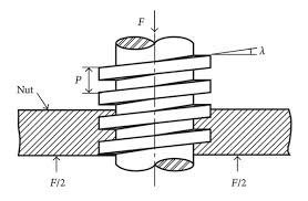
The equation for a simple single-start lead screw is:
T = F × (d_m / 2) × [(L + πμd_m) / (πd_m - μL)]
Where:
- T = Required torque
- F = Axial load
- d_m = Mean diameter of the screw
- L = Lead of the screw
- μ = Coefficient of friction
This computation informs engineers of the least amount of torque that their motor has to supply to move its load.
Friction and System Efficiency Effects
If the length of the lifting nut is relatively long and attention has been given to sliding friction and mechanical efficiency, both play a major role in determining the effective input torque.
Torque request can be modified by efficiency η:
T_actual = T / η
Where η is the thread friction, lubrication, and nut-screw losses coefficient. Lower efficiency requires the motor to generate more torque for a given load movement. Considering friction ensures the system works well under real-life conditions.
Static and Dynamic Load Calculations
Calculating Static Load Capacity
Static load calculations determine the maximum load a screw can support without yielding. This depends on material, diameter, and threading.
Engineers employ formulas for the bearing and shear stresses on threads to check that a screw can safely support the load when it is not in motion. For vertical mount applications or systems that stop under heavy loads, static load calculations are required.
Sensitivity of Moving Load Computations
Dynamic computations factor in inertia, acceleration, and deceleration forces. A moving load induces forces that are larger than its static weight.
F_dynamic = F_static + m × a
Where:
- m = Mass of the load
- a = Acceleration
This avoids the risk of undersized screws, motor overloads, or accidental back-driving during fast motion.
Lead Screw Force Calculator: Calculation of Lead Screw Forces and Torques
Axial load is the linear force of a screw when power/torque is applied. It is calculated as:
F = (2 × π × T) / L
This relationship correlates the input torque and the output linear force. With a lead screw force calculator, engineers can immediately check whether a motor can generate the required axial thrust for their application.
Analyzing the Critical Buckling Load
Long and slender screws may fail by buckling under compressive loads. The critical buckling load is given by Euler's formula:
F_critical = (π² × E × I) / (K × L_s)²
Where:
- E = Modulus of elasticity
- I = Section modulus of the screw
- K = Factor for the effective length of the column
- L_s = Unsupported screw length
Understanding the critical buckling load allows you to confidently support the screw in compression without bending.
Velocity and Resolution Calculations
Determining Linear Velocity (Travel Speed)
Lead screw system linear velocity is a function of motor speed and screw lead:
V = RPM × Lead
This calculation is essential for designing high-speed systems that ensure the motor and screw can bear the load without skipping steps or stalling.
Resolution and Step Calculations
The smallest linear travel is determined by resolution. For stepper motors:
Resolution = Lead / (Steps per revolution × Microsteps)
Finger positioning is achieved with smaller lead screws or more steps. Precision is fundamental for applications such as CNC machines or optical systems.
Accurate Lead Screw Calculations for Matching of Systems
Screw Life Expectancy Calculations
Lead screws experience fatigue under alternating load cycles. Life expectancy is estimated using:
L_10 = (C / F)^3 × 10⁶ revs
Where:
- L_10 = Expected revolutions before 10% failures occur
- C = Dynamic load rating
- F = Applied axial load
Screw life calculation ensures the system meets design requirements without premature failure and is important for medical or precision devices.
Thermal Analysis and Heating Effects
High-speed or heavy-duty operation generates heat in both the screw and the nut due to friction. Linear accuracy can be affected by thermal expansion and increased wear.
Slightly more complicated calculations estimate temperature rise using:
- Torque × speed × efficiency losses
- Material thermal properties
Heat management is especially important for continuous or precision applications.
Bottom Line!
JLCMC specifically provides this lead screw calculation guide for readers, aimed at helping customers more accurately select motors, lead screws, and nuts that meet the load and speed requirements of their projects. Safe and efficient designs require consideration of factors such as torque, thrust, static and dynamic loads, velocity, resolution, and buckling. The detailed explanation in this article helps minimize errors and enhances confidence in the long-term stability of the system.
FAQs
Q1: How to take safety factors into consideration in lead screw calculation?
Multiply the calculated loads by a safety factor (often 1.5–2) to compensate for uncertainties like material variance, misalignment, or unexpected loads.
Q2: Are there any common calculation traps to watch out for?
Failing to account for friction, dynamic effects, or critical buckling can result in undersized screws, lost steps, or mechanical failure. Always include efficiency and safety margins.
Q3: What causes the discrepancy between calculated forces and measured forces?
Real-world forces can vary due to friction, misalignment, wear, or thermal expansion. Calculations provide conservative estimates for safe design.
Keep Learning
Linear Guide Rails and Bearings: What's the Difference and Which Should You Use?
Pick any machine that moves in a straight line — a CNC router, a pick-and-place unit, a 3D printer gantry — and somewhere inside it you will find either a linear bearing riding on a round shaft or a linear guide rail carrying a carriage block. Although they are sometimes discussed interchangeably, round-shaft linear bearings and profiled linear guide rails are two different linear motion systems designed for different levels of precision, rigidity, and load capacity. Both deliver low-friction, guided,......
What Actually Goes Into a Linear Guide Rail System
A linear guide rail system is more than one rail. On its own, the rail cannot provide guided motion. What supports the load and maintains positioning accuracy is how the rail, carriage, rolling elements, and seals work together. This is a quick tour of those parts, and how they add up to a complete motion axis. For engineers speccing a new axis and buyers matching a system to a machine. If you just need the basics — what a linear guide is or the different types of linear rails — start with those two g......
What Are Linear Guides and Why Do They Matter in Factory Automation?
Every CNC machine, every pick-and-place robot, every wafer handler on a semiconductor line — they all share one fundamental need: moving something in a straight line, accurately and repeatedly. That's where linear guides come in. Despite being one of the most widely used components in factory automation, linear guides are often misunderstood — partly because the industry can't agree on what to call them. This article breaks down what linear guides actually are, what's inside them, the main types of li......
Exploring Mechanical Shaft Collars and Their Different Types
Though quite elementary in design, shaft collars serve an important mechanical purpose. In simple terms, a shaft collar is a round clamping device that can be used for axial positioning of components, acting as mechanical stops, or securing parts in place along a shaft. While they may look like simple components, shaft collars must be chosen wisely to ensure performance, accuracy, and longevity of the system. This article focuses on the common types of mechanical shaft collars in transmission systems,......
What Is a Lead Screw and How Does It Work in Motion Systems
A lead screw is a classic and common mechanical element in motion systems. It is highly relevant for the transformation of rotary motion into linear motion. This basic capability makes it indispensable in machines requiring movements, lifting, or positioning under control. This article will explore the definition, working principle, maintenance, and performance limitations of lead screws, guiding engineers, technicians, and even hobbyists on how to precisely and safely control mechanical motion. If yo......
Mastering Ball Screw Efficiency Principles and Its Pros and Cons
Ball screw efficiency is one of the primary factors that drives engineers to choose ball screws rather than traditional lead screws. Ball screw efficiency is generally at least 90%. This is a lot more than what you'll see with a lead screw, where that usually hovers around 40% or lower. This superior efficiency minimizes energy dissipation, which directly reduces parasitic heat generation and lowers overall power consumption in high-duty cycle applications. If you are interested in the performance dif......