Leveling Casters: Load Transfer and Workbench Setup
10 min
- What Changes When the Support Pad Comes Down?
- Begin with a Load Map, Not a Caster Count
- Choose the Support Arrangement Around the Job
- Check the Mounting Geometry Before Ordering
- A Practical Positioning and Leveling Sequence
- Document the Two Operating States
- FAQ about Leveling Casters
Key Takeaways
Load Separation: Assess rolling loads and stationary support loads separately; a general capacity label does not explain every operating condition.
Total Weight Sizing: Include the bench, equipment, fixtures and maximum payload in the load estimate.
Corner Reaction Differences: Four installed casters do not guarantee four equal reactions, especially on uneven floors or with equipment concentrated at one end.
Mounting & Clearance Checks: Check adjustment access, wheel sweep and pad clearance before drilling mounting holes.
Contact Verification: Level the supported frame and verify contact at every pad; a level tabletop alone does not prove that all supports carry load.
Ongoing Inspection: Recheck the installation after moving the bench or changing its equipment layout.
A workbench can roll smoothly across a workshop and still rock when somebody uses it. Wheel capacity, wheel braking and stationary support answer different questions. A leveling caster combines a wheel with an adjustable support pad, allowing the same bench to move between work areas and then stand on its feet.
The design task is to make both operating states work: the complete bench must remain manageable while rolling, and its supports must carry the intended loads after positioning. This guide follows that transition, from estimating the load at each corner to checking the finished installation. The focus is a manually repositioned workbench or equipment stand, where adjustment is occasional and the floor condition is known.
What Changes When the Support Pad Comes Down?
During travel, the load passes through the caster mounting interface, bracket, axle and wheel into the floor. In the stationary configuration, the adjustable pad becomes the primary support point. The required pad position and wheel clearance depend on the caster design. Follow the manufacturer's instructions and confirm that the caster has reached its specified stationary support condition before using the bench.
FOOT MASTER's general operating explanation describes lowering the pad to hold position and raising it to move. That establishes the functional distinction between moving and standing, without assigning any particular rating to another manufacturer's caster. FOOT MASTER leveling caster overview
A wheel brake usually restricts wheel rotation; some caster designs also restrict swiveling. A leveling pad adds a different function: it changes the support condition and allows height adjustment. Consequently, specifying a brake is not a substitute for deciding how a bench should be supported during work.
JLCMC's DEPN leveling caster series is listed with flat plate and screw swivel mounting variants. Its product information identifies an ADC body, white finish, heavy-duty classification and no brake. Those are family attributes; the exact dimensional variant still needs to be selected and checked against its drawing.
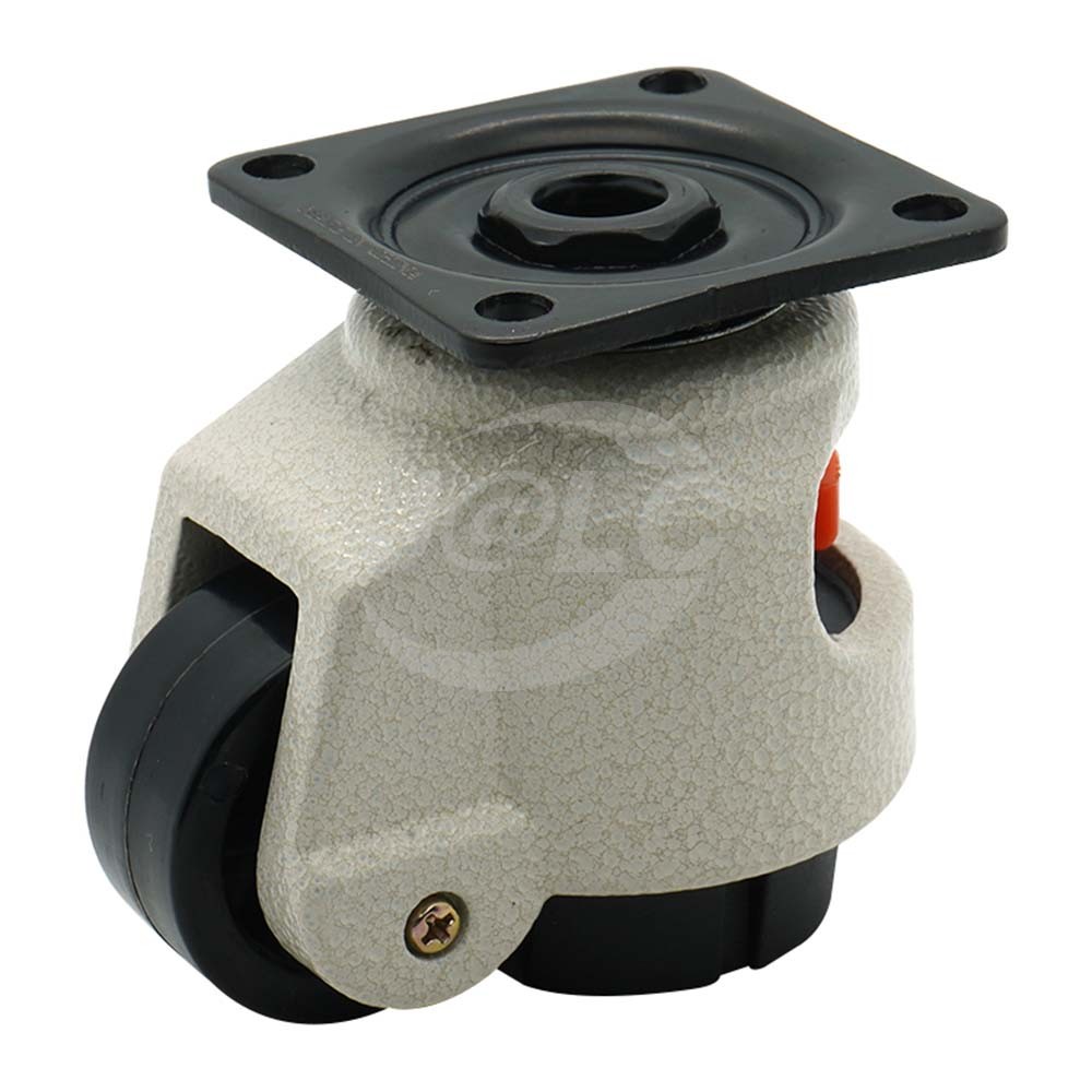
JLCMC DEPN series product image. The pictured configuration has a plate mount; dimensions and capacity depend on the selected variant.
Begin with a Load Map, Not a Caster Count
Prepare a simple plan view showing each support and the major masses. Include the frame, tabletop, permanently mounted equipment, stored materials and the maximum normal workpiece. Account for drawers or shelves whose contents may change. A later addition such as a vise, transformer or small machine can shift the load toward one corner without noticeably changing the bench's appearance.
Dividing total mass by four is a useful first estimate only when the load is distributed appropriately and the support arrangement behaves as assumed. It is not evidence that each wheel or pad actually carries that amount. Blickle's load-capacity guidance explicitly notes that loads on four or more casters can differ, and distinguishes dynamic capacity from static capacity. It also identifies travel conditions as relevant to selection. Blickle load-capacity guide
A Simple Example of an Off-Center Load
Consider an illustrative bench with support lines 1.2 m apart. The combined 240 kg mass has its center of gravity 0.8 m from the left support line. For a simple rigid-body model on level ground, the right support line carries \times 0.8 / 1.2 = 160\text{ kg-equivalent}$, while the left line carries 80 kg-equivalent.
If the load is also centered across the bench width and each support line shares its load equally, the two right corners carry approximately 80 kg-equivalent each and the two left corners approximately 40 kg-equivalent each. The naive quarter-load estimate would be 60 kg-equivalent per corner. The example is a static illustration, not a DEPN capacity recommendation or a complete four-support structural analysis.
Practical Takeaway
The practical lesson is to investigate the most heavily loaded support. Floor unevenness, frame flexibility, acceleration and thresholds can further change the reactions. Where these effects matter, obtain a load assessment appropriate to the actual structure and use the selected caster's stated operating conditions.
Choose the Support Arrangement Around the Job
| Arrangement | Main benefit | Best-fit operating pattern | Check before choosing |
|---|---|---|---|
| Conventional casters with suitable brakes | Convenient movement and parking | Equipment moved frequently between tasks | What the brake restrains, wheel compliance and floor conditions |
| Integrated leveling casters | Mobility and adjustable stationary support in one assembly | Bench moved occasionally, then used at a fixed station | Pad adjustment, moving and standing limits, access to controls |
| Separate wheels and leveling feet | Independent placement of rolling and standing supports | Equipment needing a deliberate support footprint | Clearance, load transfer sequence and additional mounting space |
| Fixed feet or anchored supports | Dedicated stationary support | Equipment rarely relocated | Floor interface, anchoring needs and future relocation method |
This comparison concerns functions rather than a universal ranking. A frequently moved trolley may be inconvenient with manually adjusted feet. Conversely, a workbench that remains in place for weeks may benefit from a deliberate leveling step after each relocation.
Check the Mounting Geometry Before Ordering
1Support the Plate or Threaded Connection Properly
For a plate mount, compare the hole pattern, plate envelope and fastener access with the bench leg or mounting bracket. The local structure must transfer the load into the frame. A caster attached through an unsupported thin panel can move even when the caster itself is adequate.
For a threaded mounting variant, check the thread form, size, engagement and mating part. Do not assume that a stem fitting into a hole proves sufficient engagement or bending resistance. The attachment design and fastening method need to match the selected caster and supporting material.
2Reserve Access for Adjustment
Model the hand or tool space around the adjustment control. A caster can fit beneath a leg while its knob becomes inaccessible behind a cross-brace. Check access after panels, shelves and nearby casters have been installed, not only in an empty frame model.
Also check the swivel envelope. The wheel and bracket may occupy more space during a turn than when shown aligned with the bench. Inspect clearance around feet, neighboring casters, cable trays and the operator's shoes.
3Separate Adjustment Travel from Obstacle Clearance
Leveling travel accommodates a permitted height difference at the final location. It does not make a small wheel suitable for every threshold on the route. Examine door transitions, floor joints and ramps independently. Keep cables, hoses and loose objects out of the travel path, and confirm that the pad can retract sufficiently for the approved moving configuration.
A Practical Positioning and Leveling Sequence
Prepare the Bench for Movement
Secure loose contents, close drawers and place movable equipment in the intended transport position. Release the stationary support according to the caster's instructions, confirming that every pad is clear enough for travel. One pad left dragging can make the bench unexpectedly difficult to steer.
Position and Initiate Support Transfer
At the new position, establish the intended orientation and working clearance before lowering the pads. Start with small adjustments and observe the frame as load transfers. Avoid making a large correction at a single corner simply because it is easiest to reach; this can twist a flexible frame and change the load elsewhere.
Level Datum and Confirm Contact
Level using a suitable datum on the structure or work surface. Then check for rocking and confirm pad contact. These are separate observations: a surface can read level while one support is lightly loaded. If the frame includes alignment-sensitive equipment, use its installation requirements to determine what level and support consistency are acceptable.
Verify Under Operating Load
Finally, check the bench with its normal operating load in place. Apply representative work forces within the intended use and observe movement at the feet, mounting brackets and tabletop. If the bench shifts or twists, identify the source before increasing pad extension. More extension is not a general cure for inadequate frame stiffness or an unsuitable floor.
Document the Two Operating States
A short setup record makes future moves more consistent. Record the installed caster part numbers, maximum intended payload, normal equipment positions, mounting method and approved travel route. Add a photo of the supported condition so operators can recognize whether the pads are correctly deployed.
The record should distinguish a relocated bench from a bench ready for work. After movement, verify pad contact, level and surrounding clearances again. After a payload change, revisit the load map. If a heavy accessory moves from the center to an edge, the original corner-load assumptions may no longer apply even though the total weight remains unchanged.
When evaluating JLCMC's leveling caster range, narrow the choice by mounting interface and adjustment access before comparing the selected variant's dimensions and load information. Resolve whether any stated capacity applies to one unit or a set, and to moving or stationary service, before treating it as a design limit.
FAQ about Leveling Casters
Q: Can I use the headline capacity multiplied by four?
Only after confirming what the rating means and whether the load distribution supports that calculation. A per-unit rating, a recommended set capacity and a stationary capacity describe different things. Unequal loading and travel conditions also need consideration.
Q: Does a leveling caster need a wheel brake?
That depends on the operating sequence and the product design. The support pad provides the stationary support function for many leveling casters. A separate brake may be useful during positioning, but it should not be assumed to be present. JLCMC lists DEPN's brake form as none.
Q: Should all four adjustment knobs be turned equally?
Equal turns do not necessarily produce equal support because the starting heights and floor elevations can differ. Adjust to the intended final geometry and verify support contact. Follow the selected product's adjustment limits.
Q: Can a leveling caster make a tall bench resistant to tipping?
A suitable support arrangement can improve stationary behavior, but tipping depends on the complete assembly, its center of gravity, support footprint and external forces. A leveling pad does not remove the need to assess those factors.
Q: Is a rubber support pad automatically a vibration isolator?
No. Vibration isolation requires appropriate stiffness, loading and frequency behavior. A pad that provides grip or floor protection should not be assigned an isolation percentage without relevant data.
Q: What should be inspected after repeated moves?
Check the attachment, wheel condition, adjustment mechanism, pad surface and any permanent deformation of the supporting frame. Reconfirm that controls remain accessible and that the supported bench does not rock under its normal load.
Conclusion: Leveling Casters and Workbench Load Transfer
Select leveling casters by considering the entire move-and-support sequence. Map the loads, verify the mounting geometry and adjustment access, then commission the stationary condition with the real payload. The result should be a bench that can be repositioned as intended and supported consistently when work resumes.
Keep Learning
Leveling Casters: Load Transfer and Workbench Setup
Key Takeaways Load Separation: Assess rolling loads and stationary support loads separately; a general capacity label does not explain every operating condition. Total Weight Sizing: Include the bench, equipment, fixtures and maximum payload in the load estimate. Corner Reaction Differences: Four installed casters do not guarantee four equal reactions, especially on uneven floors or with equipment concentrated at one end. Mounting & Clearance Checks: Check adjustment access, wheel sweep and pad cleara......
How to Identify V Belts and Their Types to Improve Factory Automation Efficiency
What Is a V-Belt? A V-belt is a flexible power transmission belt with a trapezoidal (V-shaped) cross-section. It transmits torque through the friction generated between the belt’s sidewalls and the grooves of a pulley. Typically constructed from rubber compounds reinforced with fiber or steel cords, V-belts combine strength with flexibility. They are designed to improve transmission efficiency, reduce slippage, and dampen vibration and noise. As a result, V-belts are widely used in applications such a......
How to Tension a Belt: Exact Methods for Peak Drive Performance
Belt tensioning is the single variable that determines whether a power transmission system operates efficiently or consumes itself from the inside out. Get it wrong, and the damage extends far beyond the belt itself—bearings overload, pulleys wear unevenly, and shaft seals begin leaking. There is no warning siren before a belt snaps; the first indication of trouble is often slippage under load or the acrid smell of overheated rubber. By that point, the failure has already propagated through the drive ......
Types of Conveyor Belt in Warehouse Operations Across Industries
A few years ago, I walked through a mid-sized distribution center in the Midwest that had just finished its first automation retrofit. What struck me wasn't the robotics or the software dashboards—it was the conveyor belt. Hundreds of meters of it, running at different speeds, handling everything from fasteners to equipment hardware, all while the floor manager tracked throughput on a tablet. That single piece of equipment, often overlooked, turned out to be the backbone of the entire operation. Conve......
V-Belt Measurement for Accurate Sizing and Replacement
A V-belt is a power transmission belt with a V-shaped cross-section that efficiently transmits motion between pulleys through wedging friction. How to Measure a V-Belt (Vee Belt) Beginners often make several common mistakes when measuring V-belt size, such as estimating length by folding the belt, using a simple ruler for approximate measurement, ignoring the belt cross-section, or measuring the belt in a slack condition. These are incorrect practices and can lead to improper belt selection or even da......
Best Conveyor Belt Materials & Their Uses
Conveyor belts are the backbone of modern manufacturing and distribution, silently driving efficiency across countless operations. But their performance isn't just about motors or pulleys—it hinges on one critical factor: the material used for conveyor belt construction. Choosing the wrong conveyor belt material can quickly lead to operational headaches—premature wear, product damage, contamination risks, and soaring maintenance costs. A conveyor belt works under constant stress. It bends around pulle......