O-Ring Groove Design Guide: Squeeze, Stretch and Gland Fill
21 min
- Key Takeaways
- 1. What Is an O-Ring Groove?
- 2. Identify the Seal Configuration First
- 3. The Main O-Ring Groove Dimensions
- 4. How to Calculate O-Ring Squeeze
- 5. How O-Ring Stretch Changes the Design
- 6. How to Calculate O-Ring Gland Fill
- 7. Clearance Gap and O-Ring Extrusion
- 8. Groove Width, Corner Radius and Edge Design
- 9. Static Face Seal Groove Design
- 10. Dynamic O-Ring Groove Design
- 11. Tolerance Stack: A Worked Example
- 12. Groove Design in Mechatronic Equipment
- Common O-Ring Groove Design Mistakes
- O-Ring Groove Design Checklist
- Frequently Asked Questions
- Conclusion
An O-Ring can have the correct material, hardness and nominal size—and still leak because the groove was designed incorrectly.
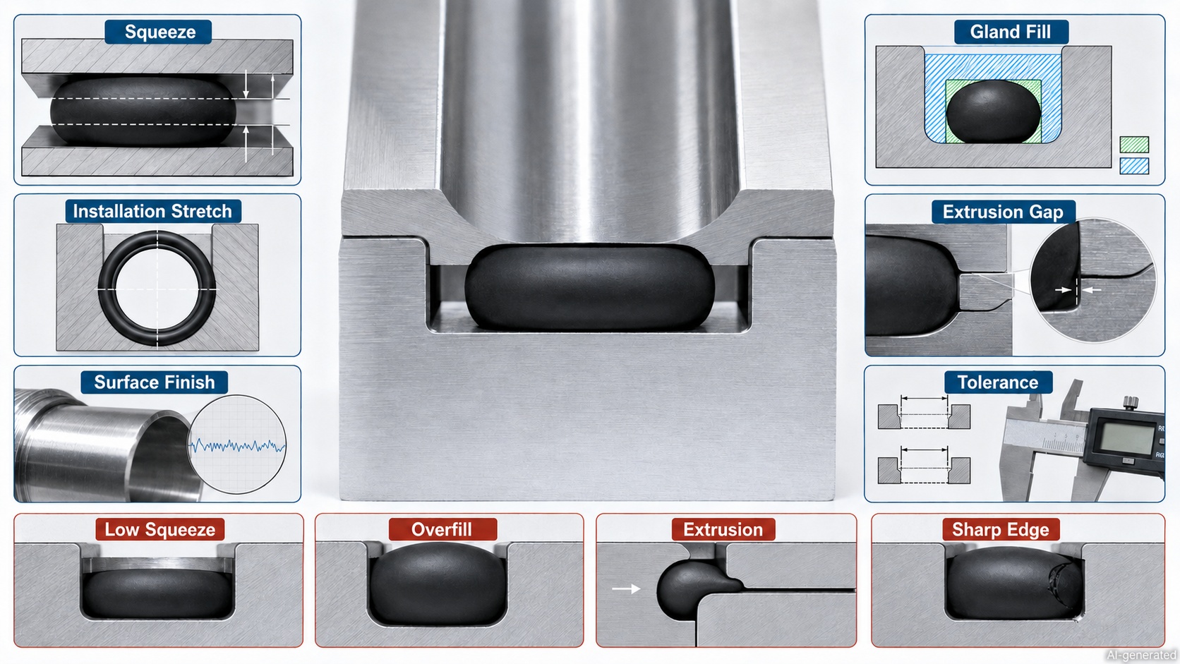
The groove, also called the gland or housing, controls how much the O-Ring is compressed, how securely it is supported and how much space remains for pressure deformation, thermal expansion and fluid-induced swelling. If the groove is too deep, the seal may not develop enough contact pressure. If it is too shallow or narrow, excessive squeeze and gland fill can increase friction, assembly force and compression set.
Reliable O-Ring groove design therefore requires more than selecting a convenient slot around a shaft or cover. Engineers must evaluate squeeze, stretch, gland fill, clearance, pressure direction, surface finish and the full tolerance stack.
This guide explains those relationships for static face seals, radial piston and rod seals, reciprocating applications and common mechatronic assemblies.
Key Takeaways
· O-Ring groove depth controls squeeze.
· Groove width strongly affects gland fill and room for material expansion.
· Stretch changes both inside diameter and cross-section.
· Static applications can generally tolerate more squeeze than dynamic applications.
· The gland should maintain sufficient empty volume for thermal expansion, swelling and
deformation.
· High pressure alone does not determine extrusion risk; clearance, hardness, temperature and pressure cycling also matter.
· Radial, face and dynamic seals require different groove dimensions.
· Nominal dimensions are not enough—worst-case tolerances must also be checked.
· Backup rings support an O-Ring against extrusion but do not correct every groove-design problem.
· Final dimensions should be confirmed against the applicable standard, supplier data and application testing.
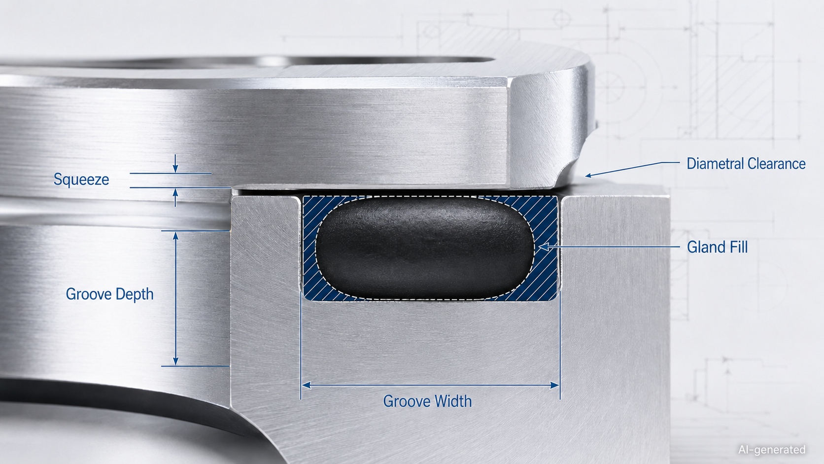
1. What Is an O-Ring Groove?
An O-Ring groove is the machined or molded cavity that contains and supports the seal. Together, the groove and the opposing mating surface form the complete gland.
The groove performs several jobs at once:
· Positions the O-Ring during assembly
· Produces the required initial squeeze
· Supports the seal under pressure
· Controls lateral movement
· Provides space for deformation and swelling
· Protects the seal from excessive extrusion
· Helps maintain sealing contact through dimensional tolerances
The latest ISO 3601-2:2025 defines housing dimensions for Class A O-Ring products used in general industrial applications and Class B products used with selected metric hardware. It covers hydraulic and pneumatic arrangements with and without backup rings.
In the standard, “housing” refers to both the groove or cavity and the mating surface that confines the O-Ring. That distinction matters: groove depth alone does not determine squeeze. The final assembled distance between the groove bottom and the opposing surface does.
Standard dimensions are valuable starting points, but special applications may need dimensions agreed between the seal manufacturer and the equipment designer. Vacuum equipment, aggressive chemicals, unusually large thermal changes, plastic housings and miniature fluid systems are common examples.
2. Identify the Seal Configuration First
Before calculating groove dimensions, determine how the O-Ring will be installed and whether the mating components move.
| Seal configuration | Compression direction | Typical applications | Main design priorities |
| Static face seal | Axial | Covers, flanges, manifolds and sensor housings | Squeeze, pressure direction and housing stiffness |
| Static piston seal | Radial | Plugs, stationary pistons and valve cartridges | Stretch, clearance and extrusion support |
| Static rod seal | Radial | Tube connections, shafts and stationary rods | Outside-diameter compression and clearance |
| Reciprocating piston seal | Radial | Pneumatic and hydraulic cylinders | Friction, wear, lubrication and spiral failure |
| Reciprocating rod seal | Radial | Actuator rods and dosing equipment | Surface finish, contamination and side loading |
| Rotary seal | Radial | Slow shafts and rotary fittings | Heat, lubrication and low squeeze |
| Vacuum seal | Axial or radial | Vacuum grippers, chambers and test equipment | Permeability, surface condition and cleanliness |
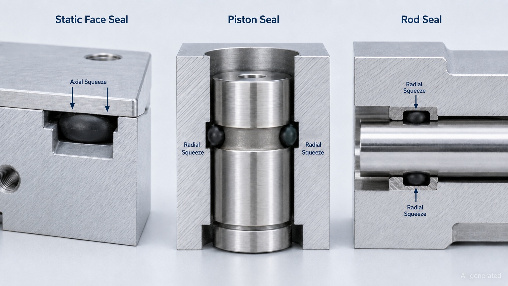
A static face seal and a reciprocating piston seal should not use the same groove simply because the selected O-Ring has the same cross-section.
Static joints have no continuous sliding contact, so they can normally use greater squeeze. Dynamic applications require enough compression to seal while limiting friction, heat and wear.
3. The Main O-Ring Groove Dimensions
The basic dimensions depend on the seal arrangement, but most calculations use the following variables:
· d1: free O-Ring inside diameter
· d2: free O-Ring cross-section
· h: assembled gland height
· w: groove width
· Dg: groove root or bottom diameter
· Db: bore diameter
· Dr: rod diameter
· r: groove corner radius
· e: clearance or extrusion gap
For a rectangular static face groove, the gland height is approximately equal to the groove depth after assembly.
For a piston groove:

For a rod groove machined into the housing:

These equations describe the nominal radial distance occupied by the O-Ring. Actual squeeze must still be checked using the minimum and maximum dimensions of the seal, groove, bore and rod.
A groove drawing should normally specify:
· Groove diameter or path
· Groove depth
· Groove width
· Corner radius
· Lead-in chamfer
· Surface-finish requirement
· Dimensional tolerances
· Mating-part clearance
· Backup-ring provision, when required
If one of these is missing, the drawing may look complete while the sealing system remains only partly defined.
4. How to Calculate O-Ring Squeeze
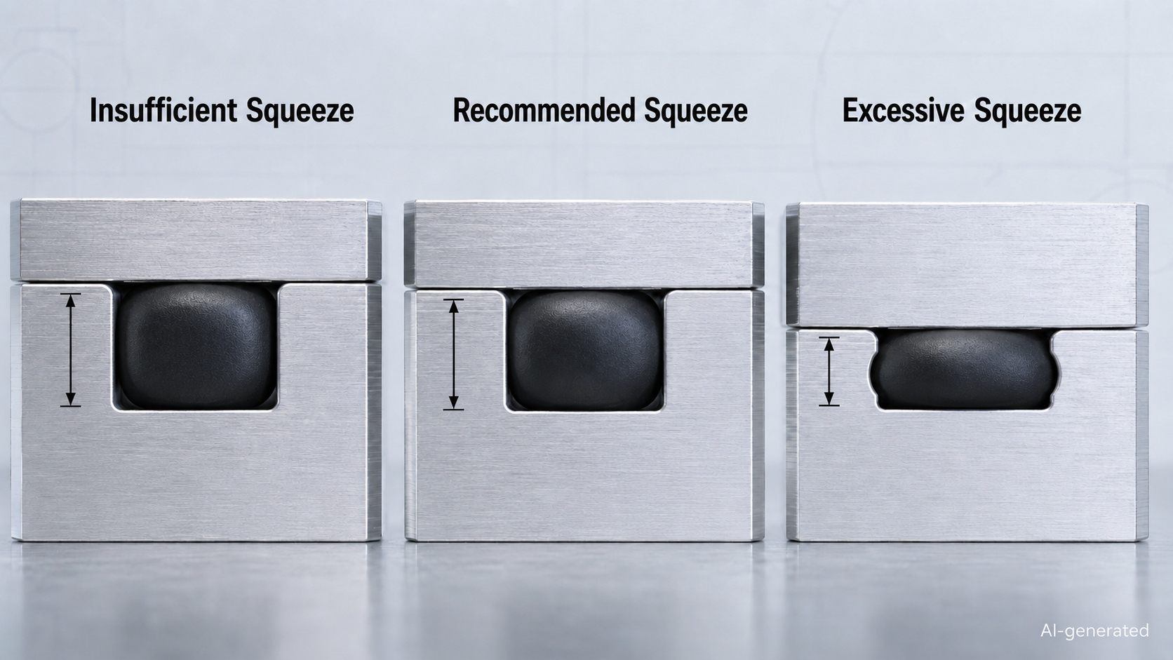
Squeeze is the reduction in the O-Ring cross-sectional height after assembly. It creates the initial sealing contact before system pressure is applied.
The squeeze percentage is:

Where:
· d2installed is the installed O-Ring cross-section
· h is the assembled gland height
If the O-Ring is not stretched, the installed cross-section can initially be treated as its free cross-section. When meaningful stretch is present, its effect on cross-section should be included.
Example
Suppose an O-Ring has a 3.00 mm cross-section and the assembled gland height is 2.25 mm:

The seal therefore has 25% nominal squeeze.
Common Preliminary Squeeze Ranges
The following ranges are general design starting points rather than universal requirements:
| Application | Common preliminary squeeze |
| Static radial seal | Approximately 15–25% |
| Static face seal | Approximately 20–30% |
| Reciprocating seal | Approximately 8–18% |
| Slow rotary seal | Approximately 0–10% |
Exact recommendations vary with cross-section, material, hardness, pressure, temperature, friction and the selected design standard. The Parker O-Ring Handbook provides application-specific gland tables rather than treating one percentage as suitable for every seal.
What Happens When Squeeze Is Too Low?
Insufficient squeeze may cause:
· Leakage at low pressure
· Poor sealing during startup
· Sensitivity to surface imperfections
· Loss of contact after compression set
· Leakage during vibration or temperature cycling
System pressure can energize an O-Ring, but it should not be expected to rescue a gland with inadequate initial contact.
What Happens When Squeeze Is Too High?
Excessive squeeze can cause:
· High assembly force
· Increased friction
· Heat generation
· Accelerated wear
· Permanent compression set
· Housing deformation
· Seal cutting or pinching
· Reduced space for swelling
More squeeze is therefore not a free reliability upgrade. Beyond the appropriate range, it mostly upgrades the number of ways the seal can fail.
5. How O-Ring Stretch Changes the Design
An O-Ring installed over a piston, plug or shaft is usually stretched slightly so that it remains seated in the groove.
Stretch is calculated from the installed diameter and the free inside diameter:

For example, installing an O-Ring with a 40 mm free inside diameter over a 41.2 mm groove root gives:

Stretch Reduces the Cross-Section
Elastomer volume remains approximately constant during installation. As the ring becomes longer, its cross-sectional area becomes smaller.
An approximate installed cross-section is:

Where (s) is stretch expressed as a decimal.
For a 3.00 mm cross-section at 3% stretch:

The change looks small, but it reduces the available squeeze and gland fill. In a close-tolerance miniature groove, a few hundredths of a millimeter may matter.
A practical rule is that every 1% increase in circumference produces approximately a 0.5% reduction in cross-sectional diameter.
Why Excessive Stretch Is a Problem
Too much stretch can:
· Reduce effective squeeze
· Accelerate stress relaxation
· Increase the risk of cracking
· Make installation more difficult
· Cause uneven seating
· Reduce the service life of the seal
For many ordinary radial designs, low single-digit stretch is preferred. The exact allowable value depends on O-Ring size, material elongation, assembly method and application.
An O-Ring placed in an internal groove may instead experience controlled outside-diameter compression. Excessive compression can make the ring buckle or twist, so it must also be checked against the selected design guide.
For more information about free dimensions and size tolerances, see the O-Ring Size Guide: How to Measure and Choose the Right Size.
6. How to Calculate O-Ring Gland Fill
Gland fill is the percentage of available groove volume occupied by the O-Ring.

For an initial rectangular-groove estimate, where the seal and groove follow approximately the same mean path:

Where:
· w is groove width
· h is assembled gland height
Example
Using a 3.00 mm O-Ring, a 2.25 mm groove depth and a 4.20 mm groove width:

This provides approximately 25% nominal empty space.
Why Empty Space Is Necessary
The O-Ring needs room for:
· Pressure-driven deformation
· Thermal expansion
· Fluid-induced swelling
· Manufacturing tolerances
· Cross-sectional variation
· Installation movement
A useful general rule is to gland fill is commonly designed within approximately 60%–85% of the available groove volume. Many designs begin near 70–75% nominal fill to preserve adequate margin. Trelleborg likewise recommends limiting groove fill so that thermal expansion, volume swell and tolerances do not completely pack the gland.
The correct value depends on the application. An elastomer expected to swell in the operating fluid requires more allowance than a dimensionally stable compound in a controlled indoor environment.
Check Maximum Fill, Not Just Nominal Fill
Worst-case gland fill should consider:
· Maximum O-Ring cross-section
· Minimum groove depth
· Minimum groove width
· Stretch-induced cross-section change
· Maximum expected fluid swell
· Temperature-related expansion
· Groove corner radii
· Coatings or plating that reduce groove volume
A groove at 75% nominal fill can exceed 90% under an unfavorable tolerance and swelling combination. Elastomers are flexible, but they are not especially talented at disappearing.
Material swell and temperature performance should be checked using the O-Ring Material Guide: NBR, FKM, EPDM, Silicone and FFKM.
7. Clearance Gap and O-Ring Extrusion
Under pressure, the O-Ring moves toward the low-pressure side of the groove. If a gap exists between the mating components, the elastomer may be forced into it.
This can produce:
· Extruded edges
· Nibbling
· Small bites or tears
· Rapid leakage
· Progressive damage during pressure cycling
Extrusion risk depends on the interaction of:
· Maximum pressure
· Pressure direction
· Pressure cycling
· Clearance gap
· O-Ring hardness
· Material strength
· Operating temperature
· Cross-section
· Component deflection
· Backup-ring support
A harder O-Ring generally resists extrusion better than a softer one, but hardness alone cannot compensate for an excessive gap.
Radial vs Diametral Clearance
For a centered piston, nominal radial clearance is:

Where Dp is piston diameter.
However, pressure, gravity and side loading can move the piston off-center. The maximum one-sided extrusion gap can then approach the full diametral clearance. Designers should therefore check the real worst-case gap rather than automatically dividing every clearance by two.
Tolerance stack, wear, bearing clearance, pressure deformation and temperature expansion can all enlarge the operating gap.
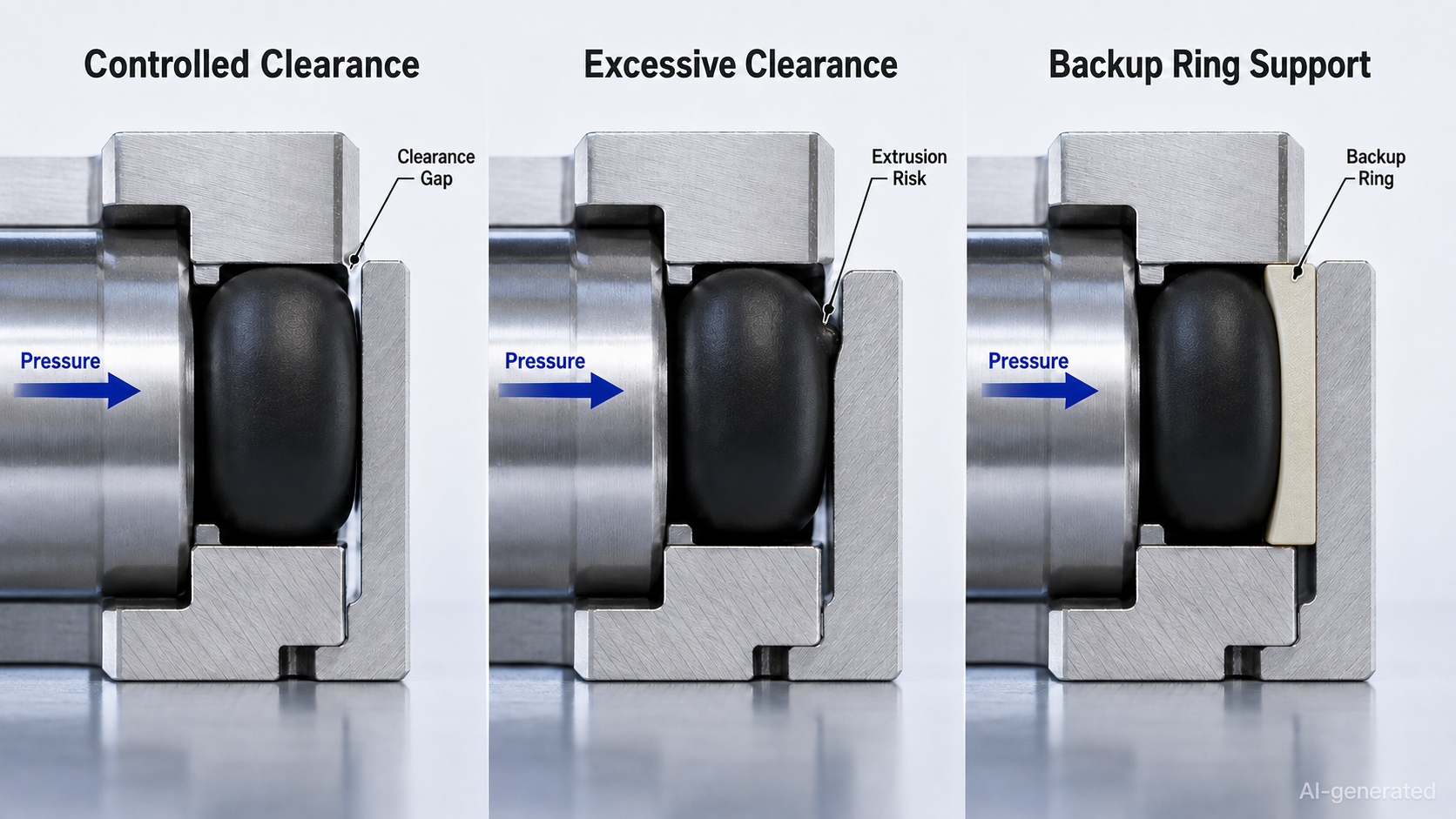
When Is a Backup Ring Needed?
A backup ring is installed beside the O-Ring on the low-pressure side to block the extrusion gap.
Use one backup ring when pressure acts consistently from one direction. Use two when pressure can reverse.
A backup ring may be appropriate when:
· Pressure is high
· Pressure pulses are severe
· The clearance cannot be reduced
· The operating temperature softens the elastomer
· A relatively soft compound is required
· The equipment experiences rapid cycling
· Component deflection increases the gap
Backup rings are supporting elements, not primary seals. They do not correct inadequate squeeze, incompatible material, poor surface finish or excessive gland fill.
ISO 3601-2 includes housing arrangements with and without anti-extrusion rings, while Trelleborg describes backup rings as support elements that prevent a pressurized elastomer from entering the sealing gap.
8. Groove Width, Corner Radius and Edge Design
Groove width must provide enough volume for the O-Ring while controlling its movement.
If the Groove Is Too Narrow
A narrow groove can cause:
· Excessive gland fill
· Seal pinching
· Assembly damage
· Insufficient swelling allowance
· High friction
· Permanent deformation
If the Groove Is Too Wide
A very wide groove can allow:
· Excessive lateral movement
· Rolling in reciprocating applications
· Twisting
· Unstable positioning
· Delayed pressure response
Dynamic grooves require particular care because the O-Ring can move, roll or spiral as the rod or piston changes direction.
Groove Corner Radius
Groove corners should not be razor-sharp. A controlled radius:
· Reduces stress concentration
· Improves machinability
· Protects the seal during installation
· Reduces the chance of cutting the elastomer
However, an excessive radius reduces usable groove volume and can interfere with a backup ring. Include the corner radius when checking minimum gland volume.
Lead-In Chamfers
An O-Ring should not be dragged across a sharp shoulder during assembly. Lead-in chamfers should be:
· Smooth
· Free from burrs
· Rounded at transitions
· Long enough to compress the seal progressively
· Designed to avoid cutting or shaving the elastomer
Threads, keyways, ports and splines that cross the installation path should be covered with a sleeve or another protective tool.
9. Static Face Seal Groove Design
A static face seal is compressed axially between two flat surfaces. It is frequently used in:
· Manifold covers
· Pump housings
· Valve plates
· Sensor enclosures
· Motor covers
· Electronic cooling plates
· Vacuum chambers
For a basic rectangular face groove, squeeze is calculated from the O-Ring cross-section and final groove depth:

Consider Pressure Direction
For internal pressure, the fluid pushes the O-Ring outward toward the groove’s outside wall. For external pressure or vacuum, the pressure differential pushes it inward.
The groove and seal should therefore be dimensioned so that the O-Ring is positioned against the low-pressure side rather than free to shift unnecessarily when pressure is applied.
Housing Stiffness Matters
A correctly calculated face groove can still leak if the cover bends between fasteners.
Check:
· Cover thickness
· Bolt spacing
· Fastener preload
· Plastic creep
· Thermal distortion
· Internal pressure
· Flatness of mating surfaces
This is especially important for plastic sensor housings and thin aluminum covers. Excessive squeeze can bow a flexible housing, while widely spaced screws may allow the joint to open between fastening points.
Rectangular vs Dovetail Grooves
A rectangular groove is normally the simplest and most economical option.
A dovetail groove can retain an O-Ring during inverted assembly or repeated servicing, but it is more difficult to machine, inspect and clean. It also makes seal installation and removal more demanding.
Dovetail geometry should therefore be used for a clear retention need—not because it looks more “engineered” in CAD.
10. Dynamic O-Ring Groove Design
Dynamic applications introduce sliding movement, which changes the design priorities.
A reciprocating O-Ring must maintain sealing contact without generating excessive friction or wear. Compared with a static seal, it generally requires:
· Lower squeeze
· More controlled surface finish
· Suitable lubrication
· Accurate alignment
· Limited side loading
· Tighter control of clearance
· Adequate room for movement
Surface Finish
The dynamic mating surface should be smooth enough to avoid abrasion but not so polished that it cannot retain an appropriate lubricant film.
Surface texture direction also matters. Scratches or machining marks running across the sealing path can form leakage channels. Circumferential or motion-compatible finishing is generally preferred over spiral lead marks.
Surface specifications should address more than a single roughness number. Peak height, valleys, waviness, lead and local scratches can all influence sealing.
Lubrication
A compatible lubricant can:
· Reduce assembly damage
· Lower breakaway friction
· Limit wear
· Reduce heat
· Help prevent twisting
The lubricant must be compatible with the elastomer and the process fluid. Petroleum grease, silicone grease and specialty assembly lubricants are not universally interchangeable.
Spiral Failure
In reciprocating systems, an O-Ring may roll rather than slide evenly. Repeated rolling creates twisting stress and diagonal damage called spiral failure.
Common causes include:
· Excessive squeeze
· Poor lubrication
· Uneven surface finish
· Side loading
· A groove that allows unstable movement
· Rapid pressure reversals
A dedicated rod or piston seal may be more reliable than an O-Ring in demanding high-speed or long-stroke equipment.
Rotary Motion
An O-Ring is normally limited to slow, well-lubricated rotary service. Continuous high-speed rotation creates frictional heating and concentrated wear.
For demanding rotary shafts, use a purpose-designed rotary seal rather than persuading a standard O-Ring to accept a job it never applied for.
11. Tolerance Stack: A Worked Example
Nominal calculations are only the beginning. Consider this simplified static face-seal design:
| Parameter | Nominal | Tolerance range |
| O-Ring cross-section | 3.00 mm | 2.90–3.10 mm |
| Groove depth | 2.25 mm | 2.20–2.30 mm |
| Groove width | 4.20 mm | 4.10–4.30 mm |
Nominal Squeeze

Minimum Squeeze
Minimum squeeze occurs with the smallest cross-section and deepest groove:

Maximum Squeeze
Maximum squeeze occurs with the largest cross-section and shallowest groove:

The nominal design says 25%, but the manufactured assembly may produce approximately 20.7–29.0% squeeze.
Nominal Gland Fill

Approximate Maximum Gland Fill
Maximum fill occurs with the largest cross-section, shallowest groove and narrowest width:

This design remains below 85% before material swelling is considered. If the compound experiences 10% volume swell, the effective fill could exceed 90%.
The example demonstrates why nominal dimensions alone are insufficient. A proper design review should calculate at least:
· Minimum squeeze
· Maximum squeeze
· Minimum gland fill
· Maximum gland fill
· Minimum and maximum stretch
· Maximum extrusion gap
· Thermal and pressure deformation
12. Groove Design in Mechatronic Equipment
O-Ring groove design has direct effects on the performance of automation, sensing and fluid-control equipment.
| Mechatronic application | Groove-design concern | Possible consequence |
| Pneumatic cylinder | Excessive dynamic squeeze | High breakaway force and inconsistent motion |
| Solenoid valve cartridge | Incorrect radial clearance | Internal leakage or extrusion |
| Vacuum gripper | Low squeeze or surface scratches | Reduced holding force |
| Sensor enclosure | Flexible cover and wide screw spacing | Water or coolant ingress |
| Liquid-cooling plate | Insufficient swelling allowance | Overfilled gland and seal damage |
| Automated dispenser | Incompatible compound swelling | Blocked movement or chemical leakage |
| Precision pump | Loose groove tolerances | Unstable dosing volume |
| Robotic end effector | Vibration and pressure cycling | Progressive loosening or leakage |
Pneumatic Cylinders
Excessive squeeze increases friction and can make cylinder movement less predictable. This is particularly troublesome in positioning systems where breakaway force affects low-speed control.
Sensor and Encoder Housings
A face-seal groove must maintain compression without deforming the enclosure. Plastic creep, temperature cycling and uneven screw tightening should be considered alongside the nominal groove depth.
Liquid-Cooling Modules
Cooling plates used around electronics, motors and testing equipment often experience repeated thermal cycles. Differential expansion between aluminum, plastic and elastomer can change both squeeze and gland volume.
Miniature Valves and Pumps
Small grooves magnify the effect of flash, scratches and dimensional variation. A deviation that is unimportant in a large hydraulic seal can consume a substantial part of the tolerance budget in a miniature valve.
More equipment-specific examples are available in O-Ring Applications in Mechatronic Systems.
Common O-Ring Groove Design Mistakes
Using the Free Cross-Section After Significant Stretch
Stretch reduces the installed cross-section. Ignoring this change can overestimate squeeze.
Selecting Groove Depth Without Checking Width
Depth controls squeeze, but width determines gland volume. Both dimensions must be calculated together.
Designing Only to Nominal Dimensions
The manufactured assembly operates somewhere within its tolerance range—not permanently at the center of the drawing.
Filling the Groove Completely
A completely packed gland leaves no allowance for swelling, expansion or pressure deformation.
Treating Hardness as the Only Extrusion Control
Hardness helps, but pressure, gap, temperature, cycling and backup support also determine extrusion resistance.
Ignoring Housing Deflection
Thin covers and plastic components may open under pressure even when the groove itself is correct.
Applying Static Dimensions to Dynamic Service
Dynamic seals need lower friction, suitable lubrication, better alignment and closer surface control.
Leaving Sharp Installation Edges
A perfect groove cannot compensate for an O-Ring sliced while passing over a thread or burr.
O-Ring Groove Design Checklist
Before releasing the drawing, confirm:
1.Is the seal static, reciprocating, rotary or used under vacuum?
2.Is it a face, piston or rod arrangement?
3.What are the O-Ring ID, cross-section and tolerances?
4.What are the minimum and maximum squeeze values?
5.How much installation stretch or compression occurs?
6.Has the installed cross-section been recalculated?
7.What are the nominal and maximum gland-fill values?
8.Has fluid-induced volume swell been included?
9.What is the maximum one-sided extrusion gap?
10.Can pressure reverse direction?
11.Is a backup ring required?
12.Are groove radii and lead-in chamfers defined?
13.Are mating surfaces free from harmful scratches and machining lead?
14.Can the housing deform under pressure or fastener preload?
15.Is the lubricant compatible with the seal and operating medium?
16.Has the design been validated across the complete temperature range?
17.Do the dimensions match the applicable ISO or supplier table?
18.Has the assembled system been tested under realistic conditions?
After the groove requirements are defined, engineers can compare available size series, materials and hardness options in the JLCMC O-Ring category. Always confirm the individual product drawing and dimensional tolerance before finalizing the groove.
Frequently Asked Questions
What is the difference between an O-Ring groove and an O-Ring gland?
The groove is the machined or molded cavity containing the O-Ring. The gland is the complete space formed by the groove and the opposing mating surface. The terms are often used interchangeably, but gland is technically the broader term.
How deep should an O-Ring groove be?
Groove depth depends on the O-Ring cross-section and required squeeze. For a face seal:
h=d2 (1 - Squeeze)
For a 3 mm cross-section at 25% squeeze:
h= 3 (1-0.25) = 2.25 mm
Tolerances and gland fill must then be checked.
What is a good O-Ring squeeze percentage?
Common preliminary values are approximately 15–30% for static radial seals, 20–30% for static face seals and 8–18% for reciprocating seals. These are not universal specifications. Material, hardness, dimensions and operating conditions can require different values.
What is the maximum O-Ring gland fill?
A common general recommendation is to keep maximum gland fill below approximately 85%. Lower nominal fill may be needed when significant fluid swelling, temperature expansion or tolerance variation is expected.
How much should an O-Ring stretch?
Many ordinary radial designs use low single-digit stretch. Excessive stretch reduces cross-section and can shorten service life. The allowable value must be checked against the seal size, compound and application.
Does stretching an O-Ring reduce its thickness?
Yes. Because elastomer volume remains approximately constant, increasing the ring circumference reduces its cross-sectional area. A 1% circumference increase produces roughly a 0.5% reduction in cross-sectional diameter.
Why does an O-Ring extrude from the groove?
Extrusion occurs when pressure pushes the elastomer into the clearance between mating components. Excessive clearance, high pressure, elevated temperature, low material hardness and pressure cycling can all contribute.
Should an O-Ring groove have sharp corners?
No. Controlled corner radii help prevent seal damage and improve machinability. The radius must still be small enough to preserve gland volume and accommodate any backup ring.
Can one groove work for both static and dynamic applications?
Not automatically. Dynamic applications usually require lower squeeze, tighter surface control, compatible lubrication and greater attention to friction, wear and seal movement.
Does a backup ring improve sealing?
A backup ring supports the O-Ring against extrusion. It is not normally the primary sealing element and does not correct inadequate squeeze, chemical incompatibility or installation damage.
Conclusion
A reliable O-Ring groove balances several connected variables rather than optimizing one dimension in isolation.
Groove depth establishes squeeze. Groove width controls gland fill. Stretch changes the installed cross-section. Clearance determines extrusion exposure. Surface condition, pressure direction, temperature and housing stiffness then influence how the complete assembly performs.
The practical design sequence is:
1.Define the seal configuration and movement.
2.Select the O-Ring size and material.
3.Calculate stretch or compression.
4.Calculate the installed cross-section.
5.Set the required squeeze.
6.Determine groove depth and width.
7.Check gland fill and material swell.
8.Calculate the worst-case extrusion gap.
9.Apply the complete tolerance stack.
10.Validate the assembly under realistic operating conditions.
An O-Ring may be circular, but good groove design should never be a process of going around in circles.
Keep Learning
O-Ring Applications in Mechatronic Systems: Design and Selection Guide
An O-Ring in a mechatronic system does more than stop fluid from escaping. It may preserve pneumatic pressure, maintain vacuum holding force, protect a sensor from coolant, contain liquid around power electronics or keep a dispensing process repeatable. This matters because mechatronic equipment connects mechanical movement with electronics, sensors and automated control. A small sealing problem can therefore become a motion problem, a measurement problem or even a system shutdown. A leaking pneumatic......
O-Ring Material Guide: NBR, FKM, EPDM, Silicone and FFKM
Choosing an O-Ring material is not simply a choice between "rubber" and "better rubber." The seal must remain flexible, chemically stable and mechanically supported throughout the actual operating cycle. A material that performs well in mineral oil may fail in steam. Another may tolerate high temperature but become too stiff during a cold startup. Even within the same polymer family, different compounds can deliver different hardness, compression set, cleanliness and service life. This guide compares ......
O-Ring Guide: Types, Materials, Sizes and Applications
An O-Ring is a circular sealing element with a round cross-section. Installed in a properly designed groove, it is compressed between two mating surfaces to prevent liquid or gas from passing through the joint. The design could hardly be simpler, yet the O-Ring is used in everything from household fittings and automotive systems to pneumatic cylinders, vacuum equipment, industrial robots and semiconductor machinery. That small ring quietly prevents leaks, protects components and keeps pressure where i......
O-Ring Size Guide: How to Measure and Choose the Right Size
An O-Ring can have the correct material, suitable hardness and excellent chemical resistance—and still leak because its dimensions are wrong. Selecting the right O-Ring size begins with three measurements: inside diameter, cross-section and outside diameter. The arithmetic is simple. The engineering decision is not. Manufacturing tolerances, groove geometry, installation stretch, operating pressure and the condition of the old seal can all change which size is actually suitable. This O-Ring size guide......
How to Install an O-Ring Without Damaging It
Installing an O-Ring looks simple: place the ring in the groove, assemble the components and move on. In practice, many O-Ring failures begin during those few seemingly harmless seconds. A burr can cut the sealing surface. An incompatible lubricant can soften or swell the material. Excessive stretching can reduce the cross-section, while rolling the ring into the groove can create a twist that later develops into spiral failure. The frustrating part is that installation damage is not always immediatel......
O-Ring Failure Guide: Causes, Symptoms and Solutions
An O-Ring rarely fails without leaving clues. A flattened cross-section may suggest compression set. Ragged edges can point to extrusion. A soft, swollen seal often indicates chemical incompatibility, while fine surface cracks may reveal heat, ozone or environmental attack. The difficulty is that several problems can produce similar symptoms—and several causes can act together. For example, an incompatible fluid may soften an O-Ring. The softened material then becomes easier to extrude through a clear......