O-Ring Applications in Mechatronic Systems: Design and Selection Guide
20 min
- Key Takeaways
- 1. What Does an O-Ring Do in a Mechatronic System?
- 2. Static and Dynamic O-Ring Applications
- 3. O-Ring Applications in Pneumatic Cylinders
- 4. Solenoid Valves, Manifolds and Pneumatic Fittings
- 5. O-Ring Applications in Vacuum Grippers
- 6. Sensors, Encoders and Electrical Enclosures
- 7. Robotic End Effectors and Tool Changers
- 8. Automated Dispensing and Fluid-Handling Equipment
- 9. Liquid-Cooling Systems for Motors and Electronics
- 10. Precision Pumps, Miniature Valves and Small O-Ring Applications
- 11. How to Select an O-Ring for Mechatronic Equipment
- 12. Common O-Ring Problems in Mechatronic Systems
- Mechatronic O-Ring Selection Checklist
- Frequently Asked Questions
- Conclusion
An O-Ring in a mechatronic system does more than stop fluid from escaping. It may preserve pneumatic pressure, maintain vacuum holding force, protect a sensor from coolant, contain liquid around power electronics or keep a dispensing process repeatable.
This matters because mechatronic equipment connects mechanical movement with electronics, sensors and automated control. A small sealing problem can therefore become a motion problem, a measurement problem or even a system shutdown.
A leaking pneumatic connection may reduce actuator force. A damaged seal in a vacuum gripper may cause missed picks. Coolant entering an encoder housing may disrupt feedback. In each case, the O-Ring is inexpensive, while the consequences of choosing it poorly are not.
This guide examines where an O-Ring is used in automation and mechatronic equipment, what each application demands and how engineers can select the right size, material, hardness and groove design.
For a broader introduction to O-Ring types, materials and dimensions, begin with the O-Ring Guide: Types, Materials, Sizes and Applications.
Key Takeaways
· An O-Ring may provide static, reciprocating, oscillating or vacuum sealing in mechatronic equipment.
· Pneumatic cylinders, solenoid valves, vacuum grippers, sensors, robotic tools and cooling modules impose different sealing requirements.
· A standard O-Ring is suitable for selected dynamic applications, but high-cycle motion may require a dedicated lip, piston or rod seal.
· Material selection must include the process medium, lubricant, cleaning agent and surrounding environment.
· Vacuum performance depends on surface condition, squeeze, contamination and gas permeability—not only visible leakage.
· Housing stiffness and fastener spacing can affect static face sealing around sensors and electronic enclosures.
· Small O-Ring applications are especially sensitive to dimensional tolerance, flash, scratches and installation damage.
· Final validation should reproduce actual pressure, temperature, movement, vibration and chemical exposure.
1. What Does an O-Ring Do in a Mechatronic System?
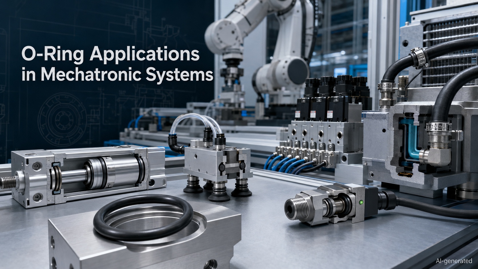
A mechatronic system combines mechanical structures, actuators, sensors, electronics and control software. The O-Ring usually operates at the interfaces between these elements.
Its main functions include:
· Retaining compressed air or hydraulic fluid
· Preventing external air from entering a vacuum circuit
· Separating two fluid channels
· Protecting electronic components from coolant, oil or water
· Sealing removable covers, cartridges and connectors
· Maintaining pressure around valves and miniature pumps
· Allowing equipment to be disassembled and serviced
· Controlling contamination in precision fluid systems
The sealing function may appear simple, but the operating conditions are often mixed. A sensor housing, for example, may experience static compression, vibration, coolant exposure, temperature cycling and repeated cleaning at the same time.
Common Mechatronic O-Ring Applications
| Component | Typical O-Ring location | Main function | Possible effect of failure |
| Pneumatic cylinder | End cap, piston or internal port | Retains compressed air | Reduced force or unstable movement |
| Solenoid valve | Cartridge, manifold or port | Separates pressure channels | Internal leakage or slow response |
| Vacuum gripper | Ejector, flange or manifold interface | Maintains the vacuum circuit | Missed picks or dropped parts |
| Sensor housing | Cover or threaded sensor body | Blocks coolant, water and dust | Unstable readings or electrical damage |
| Robotic end effector | Tool plate or pneumatic channel | Seals air and process-fluid passages | Loss of grip or process interruption |
| Automated dispenser | Valve, cartridge or reservoir | Contains adhesive or liquid | Inaccurate dosing or contamination |
| Liquid-cooling module | Pump, cold plate or connector | Retains coolant | Thermal alarms or electronic damage |
| Precision pump | Housing or fluid-port interface | Seals miniature passages | Flow drift or cross-contamination |
The O-Ring is therefore not merely a mechanical accessory. In many automated systems, its performance influences the accuracy and repeatability of the complete machine.
2. Static and Dynamic O-Ring Applications
The first selection decision is whether relative movement occurs across the sealing surface.
Static O-Ring Application
A static O-Ring seals two surfaces that do not move relative to each other during normal operation.
Common examples include:
· Sensor covers
· Valve-manifold interfaces
· Pump housings
· Pneumatic fittings
· Cold-plate covers
· Motor cooling connections
· Camera and encoder enclosures
Static seals generally experience less wear than dynamic seals, but they can still fail because of insufficient squeeze, housing deformation, compression set or chemical incompatibility.
Dynamic O-Ring Application
A dynamic O-Ring seals a component that moves relative to the sealing surface.
Movement may be:
· Reciprocating
· Rotary
· Oscillating
· Intermittent
Typical examples include selected pneumatic pistons, valve mechanisms, dosing plungers and specially designed low-speed rotary applications.
Dynamic applications introduce friction, heat and wear. Surface finish, lubrication, alignment and movement speed therefore become more important.
A standard O-Ring can perform well in selected low- or moderate-speed dynamic designs. It should not automatically replace a dedicated rod seal, piston seal or rotary shaft seal. At high cycle rates, the apparently cheaper solution can become surprisingly talented at generating downtime.
3. O-Ring Applications in Pneumatic Cylinders
Pneumatic equipment is one of the most familiar O-Ring application areas in industrial automation.
An O-Ring may be used to seal:
· Cylinder end caps
· Piston interfaces
· Cushioning components
· Internal air passages
· Adjustable fittings
· Position-sensor ports
· Manifold connections
End-Cap Sealing
The connection between the cylinder barrel and end cap is normally static. The O-Ring must retain compressed air while tolerating pressure cycles, vibration and assembly variation.
An incorrect cross-section or groove depth may produce insufficient squeeze. Excessive squeeze, meanwhile, can make assembly difficult and accelerate compression set.
Piston and Rod Sealing
Some pneumatic cylinders use O-Ring seals in reciprocating positions, particularly in compact, low-speed or cost-sensitive designs. However, many modern cylinders use purpose-designed piston and rod seals because their profiles can provide better friction, wear and pressure behavior.
When an O-Ring is used dynamically, engineers should evaluate:
· Breakaway friction
· Running friction
· Stroke speed
· Cycle frequency
· Bore and rod surface finish
· Lubrication condition
· Side loading
· Groove geometry
· Expected service life
Excessive sealing force may cause stick-slip motion. Insufficient contact can produce internal leakage and reduce the pressure difference across the piston.
How Leakage Affects Cylinder Force
The theoretical cylinder force is related to pressure and effective piston area:
F=P x A
where:
· (F) is theoretical force
· (P) is the pressure difference across the piston
· (A) is the effective piston area
Internal leakage reduces the usable pressure difference. Seal friction, bearing friction and flow losses further reduce the force available at the mechanism.
This is why a cylinder may still move while producing inconsistent acceleration, positioning or clamping force.
4. Solenoid Valves, Manifolds and Pneumatic Fittings
A solenoid valve may contain several sealing interfaces within a small body. O-Ring products can be found around cartridges, plugs, ports, manifolds and selected moving valve elements.
Solenoid Valve Cartridges
A cartridge O-Ring may separate supply, working and exhaust passages. Correct axial position is important because a seal installed across the wrong port can restrict flow or connect channels that should remain isolated.
Sharp port edges may cut the O-Ring as the cartridge enters the bore. Chamfers and suitable installation lubrication can reduce this risk.
Pneumatic Manifolds
A manifold may place multiple valves and flow channels close together. Its O-Ring seals must maintain separation between adjacent pressure paths.
Important design factors include:
· Groove alignment
· Surface flatness
· Fastener spacing
· Manifold stiffness
· Pressure direction
· Thermal expansion
· Repeated valve replacement
One missing or displaced O-Ring can create a leak that is difficult to locate because the escaping air may travel through the manifold before becoming audible.
Fittings and Connectors
O-Ring sealing is also common in straight-thread connectors and pneumatic fittings. The thread usually provides retention while the O-Ring creates the seal.
The ring should seal against a controlled surface rather than being crushed unpredictably between thread flanks. Thread sealant cannot reliably correct an incorrectly designed O-Ring seat.
5. O-Ring Applications in Vacuum Grippers
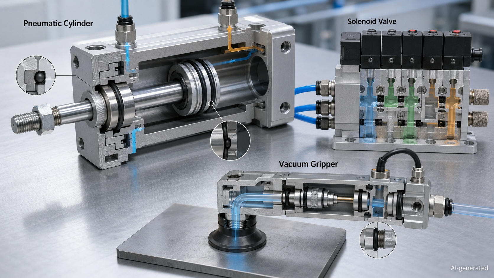
Vacuum grippers combine pneumatic supply, vacuum generation, sensing and mechanical gripping. Commercial robotic gripper units may integrate an ejector, supply and release valves, a pressure sensor and suction cups within one compact assembly.
An O-Ring may seal:
· The robot mounting interface
· Vacuum-ejector cartridges
· Internal manifold channels
· Pressure-sensor ports
· Suction-cup adapters
· Modular tool plates
The suction cup normally creates the seal against the workpiece. The O-Ring seals the internal interfaces that deliver and maintain the vacuum.
Why Small Vacuum Leaks Matter
The theoretical holding force of a vacuum cup is related to the pressure difference and effective cup area:
Actual gripping capacity must also account for acceleration, load direction, workpiece porosity, surface roughness and an appropriate safety factor.
A leaking O-Ring can reduce the pressure difference and cause:
· Longer evacuation time
· Continuous ejector operation
· Increased compressed-air consumption
· Unstable vacuum-switch signals
· Missed picks
· Dropped workpieces
Vacuum-Specific Selection Factors
Vacuum performance depends on more than ordinary fluid compatibility. Engineers should consider:
· Gas permeability
· Outgassing
· Surface finish
· Joint cleanliness
· Compression set
· Groove scratches
· Compatible vacuum lubricant
· Required vacuum level
A surface scratch running across the seal path may create a leakage channel even when the O-Ring size and material are correct.
6. Sensors, Encoders and Electrical Enclosures
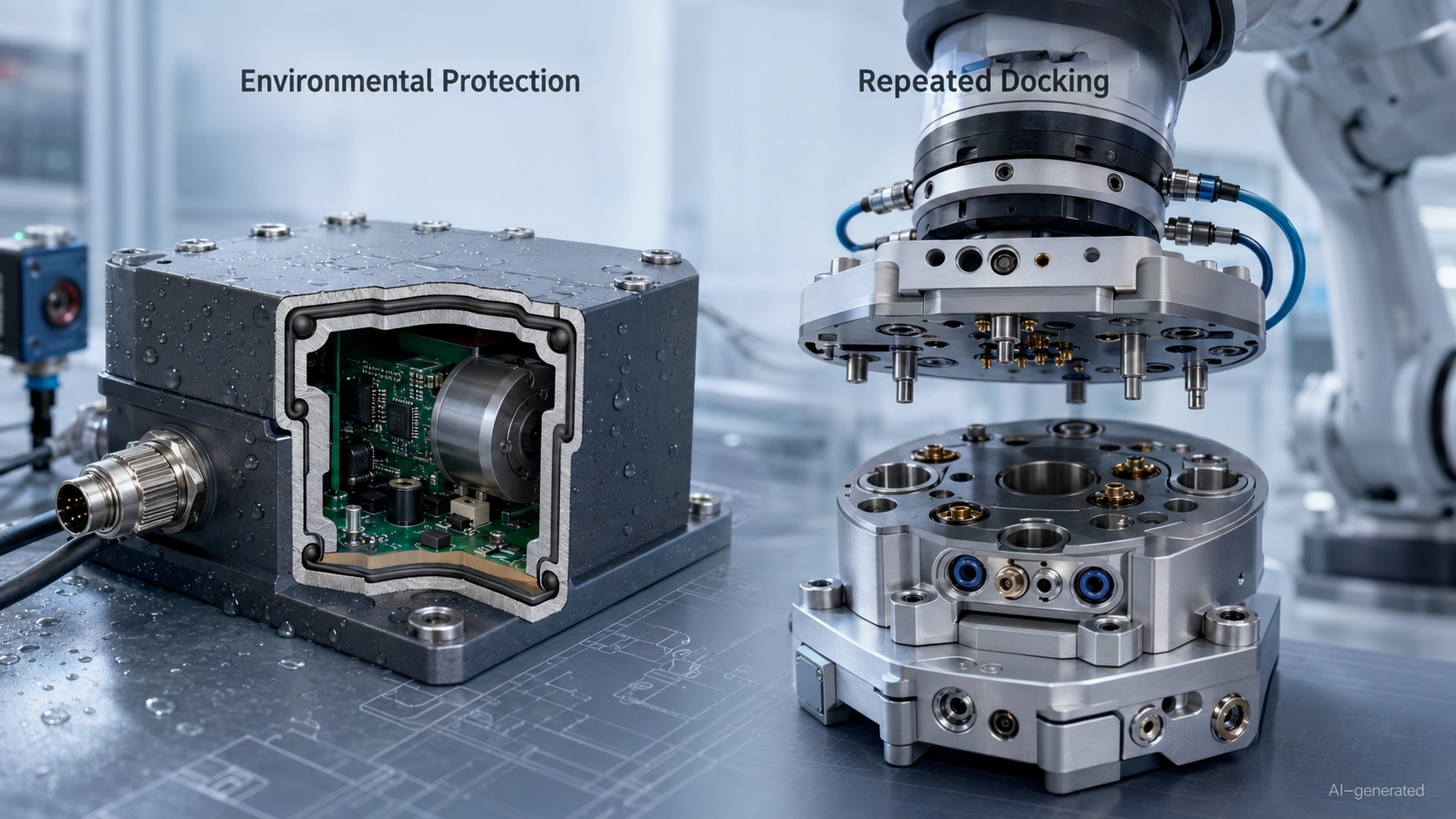
Sensors and electronic modules often use a static face or radial O-Ring to block:
· Coolant
· Cutting fluid
· Water
· Oil mist
· Dust
· Cleaning solution
· Outdoor moisture
Applications include proximity sensors, encoders, industrial cameras, pressure sensors, electrical connectors and junction boxes.
Sensor Housing Seals
An O-Ring placed beneath a sensor cover must maintain compression despite:
· Housing deflection
· Screw-load variation
· Vibration
· Temperature cycling
· Cable movement
· Repeated maintenance
A thin plastic cover may bow between fasteners. This can reduce compression in the middle of the joint even when the groove itself is dimensionally correct.
The design should therefore evaluate the complete compression path:
1.O-Ring cross-section
2.Groove depth
3.Cover thickness
4.Housing stiffness
5.Fastener position
6.Tightening sequence and torque
Sealed Industrial Connectors
Some industrial connectors use mechanical stops to control O-Ring compression. For example, ifm describes an M12 connector design in which a mechanical end stop maintains defined compression while a separate mechanism resists loosening under vibration. This illustrates an important principle: connector sealing should not depend on an operator guessing how tightly to turn the coupling.
O-Ring and IP Ratings
An O-Ring does not have an IP rating by itself. Ingress protection applies to the completed and correctly assembled enclosure.
The final performance depends on:
· Seal geometry
· Housing material
· Fastener torque
· Cable entry
· Connector design
· Surface condition
· Manufacturing tolerances
· Assembly process
A ring made from an appropriate material cannot compensate for a warped cover or an unsealed cable gland.
7. Robotic End Effectors and Tool Changers
Robotic tooling frequently combines mechanical attachment, electrical communication and pneumatic or fluid connections.
An O-Ring may be used in:
· Pneumatic gripper manifolds
· Tool-changing plates
· Vacuum channels
· Coolant passages
· Adhesive-dispensing tools
· Automatic screwdriving heads
· End-of-arm test equipment
Repeated Docking
An automatic tool changer may connect and disconnect hundreds of times. Its seals can experience:
· Repeated compression
· Sliding during engagement
· Misalignment
· Impact
· Dust and metal particles
· Lubricant loss
· Vibration
A static O-Ring that performs well in a permanently bolted flange may not survive the same number of tool-changing cycles.
Lead-in chamfers and alignment features should guide the tool before the sealing surfaces make contact. The O-Ring should not be expected to correct mechanical misalignment.
Multiple Media
A robotic end effector may contain separate channels for compressed air, vacuum, coolant and process fluid. Identical-looking seals may therefore require different materials.
Using one O-Ring compound everywhere simplifies purchasing, but only if that compound is compatible with every medium and operating condition. Convenience is useful; chemical compatibility is less open to negotiation.
8. Automated Dispensing and Fluid-Handling Equipment
Automated dispensers handle materials ranging from light lubricants to adhesives, cleaning agents, solvents and reactive chemicals.
O-Ring applications include:
· Reservoir caps
· Pump housings
· Dispensing valves
· Replaceable cartridges
· Syringe adapters
· Pressure regulators
· Mixing blocks
· Cleaning ports
Process Fluid and Cleaning Fluid
The seal must be compatible with both the dispensed material and the fluid used during maintenance.
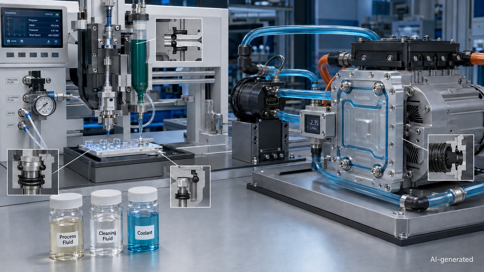
For example, an O-Ring may perform well with a lubricant but swell after repeated exposure to the solvent used to clean the dispensing head. Chemical compatibility should therefore cover:
· Main process fluid
· Hardener or catalyst
· Flush liquid
· Cleaning solvent
· Assembly lubricant
· Ambient contaminants
Dosing Accuracy
Leakage can influence dosing accuracy by changing pressure, allowing air to enter the fluid path or causing material to bypass a valve.
Compression set may also produce intermittent leakage after the machine has remained idle. A dispenser can therefore pass a short initial test and still drift after repeated production and shutdown cycles.
In high-purity or laboratory systems, extractables, particle generation and cleaning documentation may be as important as ordinary resistance to swelling.
9. Liquid-Cooling Systems for Motors and Electronics
Liquid cooling is increasingly used around electric motors, drives, battery-test systems, power electronics and high-density control equipment.
An O-Ring may seal:
· Cold plates
· Pump housings
· Coolant connectors
· Motor jackets
· Reservoirs
· Flow sensors
· Quick-disconnect interfaces
Danfoss documentation for one liquid-cooled motor, for example, recommends an O-Ring-sealed coolant connector and specifies a water-glycol coolant condition for that particular system. This demonstrates why engineers must check the equipment-specific coolant specification rather than select a seal from the word “coolant” alone.
Coolant Compatibility
A cooling liquid may contain:
· Water
· Glycol
· Corrosion inhibitors
· Biocides
· Dyes
· Anti-foaming agents
· Conductivity-control additives
EPDM is often considered for water and glycol-based service, while other compounds may be required for oils or specialty coolants. The complete formulation and temperature range must still be checked.
FKM should not automatically be treated as the premium answer to every coolant problem. Its performance with water, steam and certain additives depends on the exact compound and operating conditions.
Temperature Cycling
Cooling modules repeatedly heat and cool during operation. Different thermal-expansion rates in aluminum housings, steel fittings and polymer covers can change O-Ring compression.
The design should account for:
· Minimum startup temperature
· Maximum coolant temperature
· Peak component temperature
· Pressure during heating
· Housing expansion
· Coolant absorption
· Long-term compression set
A leak near power electronics can turn a minor sealing error into a very expensive lesson in conductivity.
10. Precision Pumps, Miniature Valves and Small O-Ring Applications
Compact pumps, miniature solenoid valves, test fixtures and analytical equipment often require very small O-Ring products.
As dimensions decrease, apparently minor defects become proportionally larger.
Critical factors include:
· Inside-diameter tolerance
· Cross-section tolerance
· Mold flash
· Parting-line condition
· Surface contamination
· Groove concentricity
· Assembly-tool geometry
· Seal identification
A small scratch that would be insignificant in a large industrial flange may cross much of the sealing width in a miniature valve.
Dead Volume and Flow Paths
In fluid-analysis and dispensing equipment, the groove and seal should not create unnecessary trapped volume. Residual fluid can affect cleaning, sample carryover and response time.
The O-Ring should remain outside the intended flow path unless the design deliberately uses pressure to energize the seal.
11. How to Select an O-Ring for Mechatronic Equipment
O-Ring selection should begin with the operating system, not with a familiar material or color.
Step 1: Identify the Seal Location
Determine whether the O-Ring seals:
· A cover
· A cylindrical cartridge
· A moving piston
· A connector
· A vacuum passage
· A coolant channel
· A process-fluid interface
This defines the basic groove and loading direction.
Step 2: Classify the Movement
Identify whether the application is:
· Static
· Reciprocating
· Rotary
· Oscillating
· Repeatedly connected and disconnected
For dynamic use, document speed, stroke, cycle frequency, lubrication and allowable friction.
Step 3: List Every Contact Medium
Include:
· Process fluid
· Coolant
· Compressed air
· Lubricant
· Cleaning agent
· Purge gas
· External oil or coolant
· Outdoor exposure
For material comparisons, see the O-Ring Material Guide: NBR, FKM, EPDM, Silicone and FFKM.
Step 4: Define the Temperature Range
Record:
· Minimum ambient temperature
· Normal operating temperature
· Maximum continuous temperature
· Short-duration peak temperature
· Temperature during cleaning
· Heat generated by nearby motors or electronics
The material must remain elastic at low temperature and resist excessive softening, chemical attack and compression set at high temperature.
Step 5: Define Pressure or Vacuum Conditions
Consider:
· Normal pressure
· Peak pressure
· Pressure cycling
· Pressure direction
· Vacuum level
· Decompression rate
· Clearance gap
High pressure and excessive clearance can cause extrusion. Vacuum systems require additional attention to permeability, outgassing and surface leakage.
Step 6: Determine the Size
An O-Ring is normally specified by its inside diameter and cross-section.
OD=ID+2(CS)
Confirm the dimensions against the groove and relevant product standard. Do not select the seal from the shaft, bore or connector size alone.
Detailed measurement methods are available in the O-Ring Size Guide: How to Measure and Choose the Right Size.
Step 7: Check the Groove and Housing
Evaluate:
· Squeeze
· Stretch
· Groove width
· Gland fill
· Clearance
· Surface finish
· Edge radii
· Cover flatness
· Housing stiffness
· Fastener spacing
Recommended groove dimensions depend on the seal type, movement and operating conditions. ISO 3601-2 covers O-Ring housing dimensions for general applications, while supplier design data may be required for the selected compound and equipment.
The O-Ring Groove Design Guide explains squeeze, stretch and gland fill in greater detail.
Step 8: Select Hardness and Support
A softer O-Ring conforms more easily to surface variation but generally has lower resistance to extrusion. A harder ring may provide greater mechanical support while requiring more assembly force.
Hardness cannot correct:
· An oversized clearance gap
· An incorrect groove depth
· Poor alignment
· A damaged sealing surface
· Chemical incompatibility
A backup ring may be required when pressure and clearance expose the elastomer to extrusion.
Step 9: Consider Maintenance
Ask:
·How often will the assembly be opened?
· Can the seal be inspected?
· Is replacement possible without removing the machine?
· Can different materials or sizes be confused?
· Is lubrication controlled?
· Is there a defined tightening sequence?
Color alone should not be used as the only identification method.
Step 10: Validate the Complete Assembly
Recommended validation may include:
| Test | What it evaluates |
| Pressure-decay test | Leakage from pressurized pneumatic or fluid circuits |
| Vacuum-decay test | Leakage into low-pressure systems |
| Thermal cycling | Compression changes caused by expansion and contraction |
| Endurance cycling | Friction, wear and compression set |
| Chemical exposure | Swelling, hardening, softening or cracking |
| Vibration test | Joint movement and fastener-related compression loss |
| Ingress test | Completed enclosure performance |
| Dimensional inspection | Groove, O-Ring and housing tolerance stack |
Published material data is a starting point. The final assembly remains the real test.
Once the operating conditions are defined, engineers can compare available materials, hardness levels and dimensional series in the JLCMC O-Ring category.
12. Common O-Ring Problems in Mechatronic Systems
Unstable Pneumatic Movement
Possible causes include:
· Internal seal leakage
· Excessive dynamic friction
· Insufficient lubrication
· Too much squeeze
· Poor cylinder alignment
· Contaminated sealing surfaces
The O-Ring should be investigated together with the guides, bearings, air supply and control valve.
Slow Vacuum Response
Possible causes include:
· Damaged O-Ring
· Loose manifold connection
· Scratched sealing face
· Porous tubing
· Worn suction cup
· Restricted vacuum line
· Incorrect vacuum-switch setting
Replacing the cup alone will not fix an internal manifold leak.
Coolant Inside a Sensor Housing
Possible causes include:
· Insufficient face-seal compression
· Warped cover
· Incorrect fastener torque
· Chemical swelling
· Installation damage
· Cable-entry leakage
The apparent O-Ring leak may actually originate at a connector or cable gland.
Repeated Seal Extrusion
Possible causes include:
· Excessive pressure
· Large clearance gap
· Soft material
· Elevated temperature
· Pressure pulsation
· Missing backup support
Simply installing a harder O-Ring may hide the underlying geometry problem.
Seal Damage After Maintenance
Possible causes include:
· Reusing a compressed seal
· Dragging it across threads
· Sharp groove edges
· Incompatible assembly lubricant
· Twisting
· Incorrect replacement size
Use suitable lead-in geometry and follow the workflow in How to Install an O-Ring Without Damaging It.
For systematic diagnosis, see the O-Ring Failure Guide: Causes, Symptoms and Solutions.
Mechatronic O-Ring Selection Checklist
Before releasing a design or ordering a replacement, confirm:
· What component is being sealed?
· Is the seal static or dynamic?
· What pressure or vacuum level is present?
· What are the minimum and maximum temperatures?
· Which process fluids contact the O-Ring?
· Which lubricants and cleaning agents are used?
· What are the required ID and cross-section?
· Which standard or dimensional series applies?
· Is the material compatible with every contact medium?
· Is the hardness suitable for the pressure and clearance?
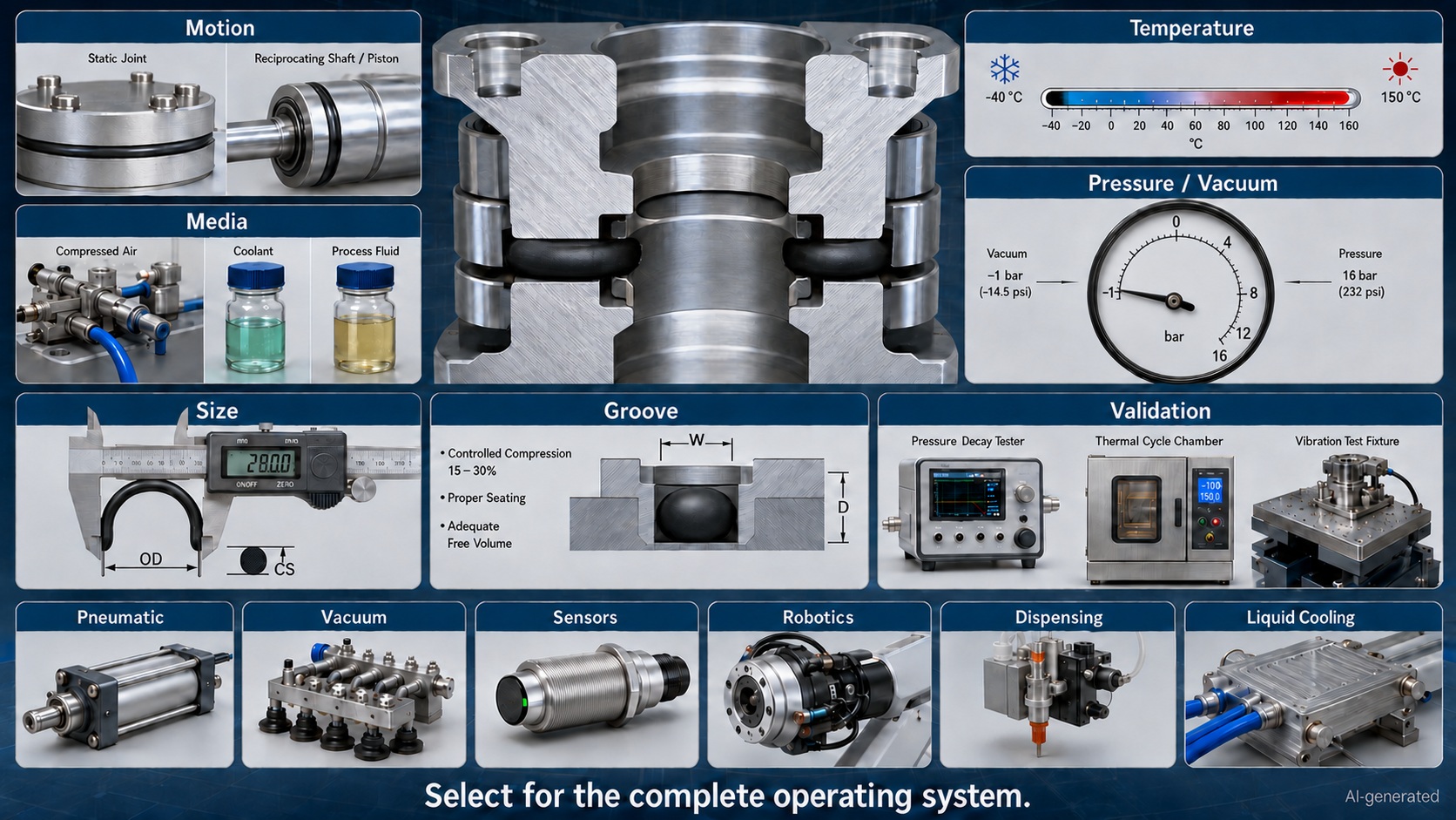
· Does the groove provide controlled squeeze and adequate free volume?
· Can the housing maintain compression during vibration and temperature cycling?
· Will the seal be repeatedly connected or serviced?
· Are cleanliness or regulatory requirements involved?
· Has the completed assembly been tested under realistic conditions?
Frequently Asked Questions
Where is an O-Ring used in mechatronic equipment?
An O-Ring is commonly used in pneumatic cylinders, solenoid valves, manifolds, vacuum grippers, sensor housings, industrial connectors, robotic tools, dispensing equipment, miniature pumps and liquid-cooling systems.
Can an O-Ring be used as a pneumatic cylinder piston seal?
Yes, an O-Ring can be used in selected reciprocating pneumatic designs. High-cycle, high-speed or low-friction cylinders may perform better with a dedicated piston or rod-seal profile.
What is the best O-Ring material for compressed air?
NBR is a common starting point for general industrial compressed-air applications because of its compatibility with many oils and lubricants. Temperature, ozone exposure, lubricant type and required service life must also be checked.
What is the best O-Ring for a vacuum gripper?
There is no universal best material. Selection depends on vacuum level, gas permeability, temperature, surface condition, lubricant, chemical exposure and required cleanliness.
Can an O-Ring provide an IP67 seal?
An O-Ring can form part of an IP67 enclosure design, but the rating applies to the completed assembly. Housing stiffness, connectors, cable entries, groove dimensions and assembly quality also affect ingress protection.
Is EPDM suitable for liquid cooling?
EPDM is often considered for water and glycol-based coolants. Compatibility must be verified against the complete coolant formulation, additives and operating-temperature range.
Is FKM always better than NBR or EPDM?
No. FKM performs well with many oils, fuels, chemicals and elevated temperatures, but it is not universally suitable for water, steam, low temperatures or every chemical. Material selection must follow the application.
Why does a pneumatic actuator stick after replacing the O-Ring?
Possible causes include excessive squeeze, incorrect size, high hardness, poor lubrication, twisting, rough surfaces or mechanical misalignment. A seal that prevents leakage may still create too much friction.
How often should an O-Ring be replaced?
There is no universal replacement interval. It depends on pressure cycles, temperature, movement, fluid exposure and the consequence of failure. Critical systems should use a validated preventive-maintenance interval rather than waiting for visible leakage.
Conclusion
An O-Ring in a mechatronic system may protect pneumatic force, vacuum holding capacity, sensor accuracy, dosing repeatability or cooling performance. Its importance comes from the interface it seals, not from its size or cost.
Reliable selection begins by identifying the seal location, movement, pressure, temperature and every contact medium. The engineer must then match the material, size, hardness and groove to the actual application before validating the completed assembly.
This process is especially important in pneumatic cylinders, vacuum grippers, robotic tools, sensor housings, automated dispensers and liquid-cooling modules, where a small leak can influence several parts of the system at once.
The O-Ring usually receives little attention when everything is working. That is exactly the arrangement it prefers.
Keep Learning
O-Ring Applications in Mechatronic Systems: Design and Selection Guide
An O-Ring in a mechatronic system does more than stop fluid from escaping. It may preserve pneumatic pressure, maintain vacuum holding force, protect a sensor from coolant, contain liquid around power electronics or keep a dispensing process repeatable. This matters because mechatronic equipment connects mechanical movement with electronics, sensors and automated control. A small sealing problem can therefore become a motion problem, a measurement problem or even a system shutdown. A leaking pneumatic......
O-Ring Material Guide: NBR, FKM, EPDM, Silicone and FFKM
Choosing an O-Ring material is not simply a choice between "rubber" and "better rubber." The seal must remain flexible, chemically stable and mechanically supported throughout the actual operating cycle. A material that performs well in mineral oil may fail in steam. Another may tolerate high temperature but become too stiff during a cold startup. Even within the same polymer family, different compounds can deliver different hardness, compression set, cleanliness and service life. This guide compares ......
O-Ring Guide: Types, Materials, Sizes and Applications
An O-Ring is a circular sealing element with a round cross-section. Installed in a properly designed groove, it is compressed between two mating surfaces to prevent liquid or gas from passing through the joint. The design could hardly be simpler, yet the O-Ring is used in everything from household fittings and automotive systems to pneumatic cylinders, vacuum equipment, industrial robots and semiconductor machinery. That small ring quietly prevents leaks, protects components and keeps pressure where i......
O-Ring Size Guide: How to Measure and Choose the Right Size
An O-Ring can have the correct material, suitable hardness and excellent chemical resistance—and still leak because its dimensions are wrong. Selecting the right O-Ring size begins with three measurements: inside diameter, cross-section and outside diameter. The arithmetic is simple. The engineering decision is not. Manufacturing tolerances, groove geometry, installation stretch, operating pressure and the condition of the old seal can all change which size is actually suitable. This O-Ring size guide......
How to Install an O-Ring Without Damaging It
Installing an O-Ring looks simple: place the ring in the groove, assemble the components and move on. In practice, many O-Ring failures begin during those few seemingly harmless seconds. A burr can cut the sealing surface. An incompatible lubricant can soften or swell the material. Excessive stretching can reduce the cross-section, while rolling the ring into the groove can create a twist that later develops into spiral failure. The frustrating part is that installation damage is not always immediatel......
O-Ring Failure Guide: Causes, Symptoms and Solutions
An O-Ring rarely fails without leaving clues. A flattened cross-section may suggest compression set. Ragged edges can point to extrusion. A soft, swollen seal often indicates chemical incompatibility, while fine surface cracks may reveal heat, ozone or environmental attack. The difficulty is that several problems can produce similar symptoms—and several causes can act together. For example, an incompatible fluid may soften an O-Ring. The softened material then becomes easier to extrude through a clear......