How to Install an O-Ring Without Damaging It
23 min
- Quick Answer: How Do You Install an O-Ring?
- Key Takeaways
- 1. Why Correct O-Ring Installation Matters
- 2. What to Check Before Installing an O-Ring
- 3. O-Ring Installation Tools and Supplies
- 4. Inspect and Clean the O-Ring Groove
- 5. Inspect the New O-Ring
- 6. How to Choose an O-Ring Lubricant
- 7. How to Install an O-Ring Step by Step
- 8. Installation Methods for Different O-Ring Applications
- 9. How to Check Whether an O-Ring Was Installed Correctly
- 10. O-Ring Maintenance and Inspection
- 11. How to Remove and Replace an O-Ring
- 12. Common O-Ring Installation Mistakes
- O-Ring Installation and Maintenance Checklist
- Frequently Asked Questions
- Conclusion
Installing an O-Ring looks simple: place the ring in the groove, assemble the components and move on. In practice, many O-Ring failures begin during those few seemingly harmless seconds.
A burr can cut the sealing surface. An incompatible lubricant can soften or swell the material. Excessive stretching can reduce the cross-section, while rolling the ring into the groove can create a twist that later develops into spiral failure.
The frustrating part is that installation damage is not always immediately visible. The assembly may pass its first pressure test and begin leaking after a few operating cycles.
This guide explains how to install an O-Ring correctly, choose a suitable lubricant, inspect the groove, avoid common assembly mistakes and build a practical O-Ring maintenance plan for industrial and mechatronic equipment.
Quick Answer: How Do You Install an O-Ring?
To install an O-Ring without damaging it:
1.Depressurize and clean the assembly.
2.Confirm the O-Ring size, material and hardness.
3.Inspect the groove and mating surfaces.
4.Remove burrs, particles and old sealant.
5.Apply a thin layer of compatible lubricant when permitted.
6.Cover exposed threads, splines and sharp edges.
7.Stretch the O-Ring only as much as necessary.
8.Place it evenly in the groove without rolling or twisting.
9.Assemble the mating components with controlled alignment.
10.Tighten fasteners evenly and test the seal gradually.
The correct procedure depends on whether the O-Ring is used in a face seal, piston seal, rod seal, fitting, valve or miniature component.
Key Takeaways
· Confirm the O-Ring identity from its specification or packaging, not its color.
· Never install a seal over an unprotected sharp edge or exposed thread.
· Cleaning agents and lubricants must be compatible with the elastomer and operating medium.
· More lubricant is not necessarily better; a thin, even film is usually sufficient.
· A standard O-Ring has no top or bottom, but a backup ring has a defined position relative to
pressure.
· Avoid local overstretching, rolling and twisting during installation.
· Do not use a screwdriver or sharp metal pick against a sealing surface.
· A replacement schedule should be based on operating risk, cycles, temperature, pressure and
chemical exposure—not an arbitrary calendar date.
· When an O-Ring repeatedly fails, inspect the entire sealing system instead of simply fitting
another identical ring.
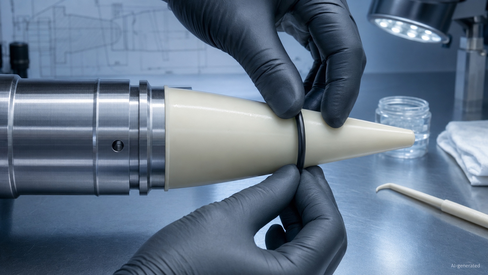
1. Why Correct O-Ring Installation Matters
An O-Ring creates a seal by being compressed inside a controlled groove. Its performance depends on its surface remaining intact and its cross-section being positioned correctly.
Installation damage can introduce a leakage path before the equipment is even started.
Typical consequences include:
· External fluid leakage
· Internal pressure loss
· Increased compressed-air consumption
· Reduced hydraulic or pneumatic force
· Unstable cylinder movement
· Loss of vacuum holding force
· Coolant or oil entering an electronic enclosure
· Process-fluid contamination
· Unexpected machine downtime
In a static cover, an installation cut may cause an obvious leak. In a reciprocating cylinder, a twisted O-Ring may survive initial testing but wear rapidly once movement begins.
The Parker O-Ring Handbook identifies sharp edges, contamination, assembly without suitable lubrication, incorrect sizing, twisting and cutting as common causes of fitting-related failure.
Correct installation cannot compensate for the wrong material, size or groove. Before assembly, verify the broader selection criteria in the O-Ring Guide: Types, Materials, Sizes and Applications.
2. What to Check Before Installing an O-Ring
A few minutes of preparation can prevent hours of disassembly later.
Confirm the O-Ring Specification
Check the following information against the drawing, bill of materials or equipment manual:
· Inside diameter
· Cross-section
· Dimensional standard or product series
· Elastomer material
· Hardness
· Compound or specification number
· Operating temperature
· Fluid compatibility
· Static or dynamic application
· Required backup ring
Do not identify the material by color alone. Color conventions vary between manufacturers, and two visually identical seals may use completely different compounds.
An AS568 dash number, for example, identifies dimensions rather than material or hardness. A dimensionally correct O-Ring can still fail if the compound is incompatible with the operating fluid.
If the original size is uncertain, consult the O-Ring Size Guide instead of relying only on measurements taken from an old, deformed seal.
Shut Down the Equipment Safely
Before opening the assembly:
· Isolate the energy source.
· Apply the required lockout procedure.
· Release hydraulic, pneumatic or process pressure.
· Drain trapped fluid where necessary.
· Allow hot components to cool.
· Support moving parts that may fall or shift.
· Follow site-specific chemical and electrical safety procedures.
A pressure gauge reading zero does not always mean every internal chamber has been depressurized. Check for trapped pressure between valves, pistons or sealed cavities.
Prepare a Clean Work Area
Keep replacement seals in their original packaging until needed. The assembly area should be free from:
· Metal chips
· Dust
· Abrasive particles
· Fibers
· Dried thread sealant
· Paint flakes
· Cleaning residue
· Unapproved grease
For miniature valves, laboratory equipment, vacuum systems and high-purity assemblies, even a particle that looks insignificant on a workbench may be large relative to the sealing interface.
3. O-Ring Installation Tools and Supplies
Most installations do not require complicated equipment, but the tools must not damage the elastomer or surrounding hardware.
Recommended Tools
· Non-marring polymer seal pick
· Blunt removal hook designed for seals
· Lint-free wipes
· Approved cleaning fluid
· Inspection light
· Magnifier for miniature seals
· Smooth installation sleeve
· Expansion cone or mandrel where required
· Compatible assembly lubricant
· Clean lubricant applicator
· Caliper or groove gauge
· Torque wrench for covers and flanges
· Pressure or vacuum test equipment
Polymer installation tools are generally safer around elastomer and soft aluminum grooves than ordinary screwdrivers or hardened steel picks.
A metal tool may slip, scratch the groove or cut the new O-Ring. The scratch left behind can become a permanent leakage channel long after the damaged seal has been replaced.
Avoid Improvised Tools
Do not use:
· Screwdrivers
· Utility knives
· Needle-nose pliers
· Sharp dental picks
· Unfinished wire hooks
· Sandpaper inside a finished groove
· Dirty shop rags
· Compressed air containing oil or water
If a dedicated tool is unavailable, use a smooth, non-marring alternative that cannot cut the seal or scratch the hardware.
4. Inspect and Clean the O-Ring Groove
The groove should be inspected every time the assembly is opened.
Look for Contamination
Remove:
· Dirt and dust
· Metal particles
· Old lubricant
· Hardened sealant
· Corrosion products
· Fragments from the previous seal
· Cleaning-agent residue
Use a cleaner compatible with the housing material, O-Ring compound and process requirements. A solvent suitable for a steel component may damage a plastic housing or leave residue that attacks the elastomer.
Inspect the Groove Surface
Check for:
· Burrs
· Sharp edges
· Scratches
· Pitting
· Corrosion
· Wear steps
· Deformation
· Incorrect machining marks
· Damaged lead-in chamfers
· Blocked fluid passages
A scratch running across the sealing path is more serious than a superficial mark running parallel to it because it can connect the high-pressure and low-pressure sides.
Do not simply polish every visible mark. Uncontrolled rework may change groove dimensions, edge radii or surface finish. Damaged critical hardware should be measured and repaired using an approved process.
Check the Mating Components
The groove is only half of the sealing interface. Inspect the cover, bore, shaft, piston or flange that contacts the O-Ring.
Pay particular attention to:
· Misalignment
· Shaft or bore wear
· Uneven flange surfaces
· Loose fasteners
· Housing distortion
· Excessive clearance
· Cross-drilled ports
· Exposed threads or splines
Groove dimensions, squeeze, stretch and available gland volume are covered in the O-Ring Groove Design Guide. The current ISO 3601-2 specifies housing dimensions for defined general industrial hydraulic and pneumatic O-Ring applications.
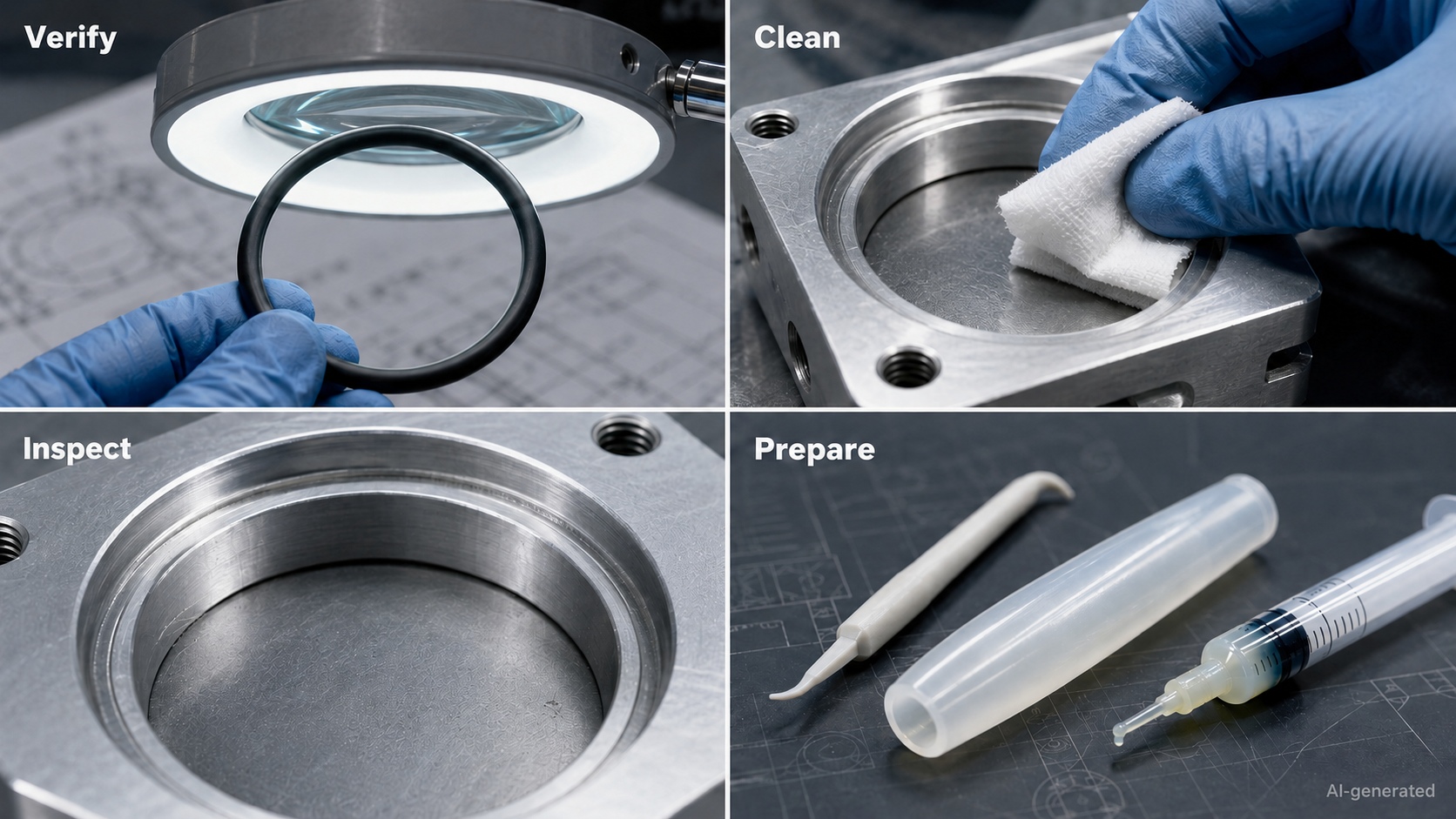
5. Inspect the New O-Ring
Do not assume that a new seal is automatically ready for installation.
Under clean lighting, inspect the complete circumference for:
· Cuts
· Cracks
· Flat spots
· Excessive flash
· Mold mismatch
· Pits
· Blisters
· Embedded particles
· Surface contamination
· Permanent deformation
· Incorrect splices on fabricated rings
Run a clean, gloved finger gently around the surface if the process permits. Do not stretch the ring aggressively during inspection.
ISO 3601-3, together with its later amendment, defines quality acceptance criteria and classifies surface imperfections for standardized O-Ring products. The acceptable defect limits depend on the applicable quality grade rather than the simple rule that every visible mark is harmless or unacceptable.
If the O-Ring has an unknown history, damaged packaging or an unverified material specification, do not install it in a critical application.
6. How to Choose an O-Ring Lubricant
Lubrication can reduce assembly friction, help the O-Ring settle into the groove and protect it during initial movement. However, the wrong lubricant can cause swelling, softening, hardening, contamination or process failure.
The lubricant must be compatible with:
· The O-Ring material
· The operating fluid
· The housing material
· The working temperature
· The surrounding components
· Cleanliness requirements
· Industry regulations
General Lubricant Considerations
| Lubricant option | Possible use | Important caution |
| The system’s operating fluid | Hydraulic or lubricated-fluid assemblies | Use only if the fluid is compatible and safe for assembly handling |
| Silicone-based grease | Selected static seals, water fittings and general assembly | Verify compatibility with silicone elastomers, sensors, coatings and contamination-sensitive processes |
| Petroleum-based oil or grease | Selected NBR and oil-service assemblies | May be unsuitable for EPDM and other petroleum-sensitive compounds |
| PFPE lubricant | Chemical, oxygen-compatible or vacuum applications when specifically approved | Expensive and application-specific; use the required cleanliness procedure |
| Water-based assembly lubricant | Selected pneumatic or production assembly processes | Confirm drying behavior, corrosion risk and material compatibility |
| Dry-film assembly aid | Clean or low-residue applications | Use only a product approved for the seal and process |
This table provides selection considerations, not universal lubricant assignments. Compatibility must be verified for the exact compound and service conditions.
Lubricants to Avoid Unless Approved
Do not automatically use:
· Petroleum jelly
· Motor oil
· General-purpose bearing grease
· Hand soap
· Dishwashing liquid
· Adhesive
· Thread-locking compound
· Silicone spray
· An unidentified workshop lubricant
A familiar lubricant is not necessarily a compatible lubricant.
How Much Lubricant Should Be Applied?
Apply a thin, uniform film to the O-Ring and relevant installation surface. The seal should appear lightly coated, not buried in grease.
Excess lubricant can:
· Attract contamination
· Block small fluid passages
· Interfere with adhesives or coatings
· Enter optical or electronic components
· Affect vacuum performance
· Contaminate process fluid
· Make the ring difficult to control during assembly
Special-Service Warning
Oxygen, semiconductor, medical, food-processing and high-vacuum systems may require specific lubricants, cleaning processes and documentation.
Never apply an ordinary hydrocarbon grease to an oxygen-service assembly. Follow the equipment manufacturer’s approved material, lubricant and cleanliness procedure.
Material compatibility and hardness considerations are explained in the O-Ring Material Guide.
7. How to Install an O-Ring Step by Step
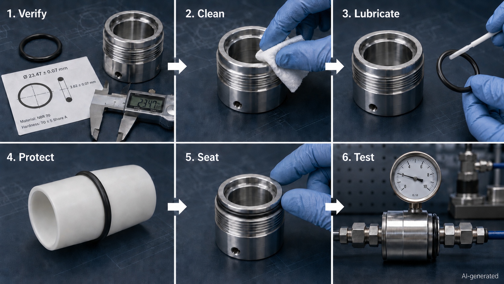
The following procedure applies to many general industrial assemblies. Product-specific instructions take priority when available.
Step 1: Verify the Part
Compare the new O-Ring with the specification and packaging.
Confirm:
· Correct size
· Correct material
· Correct hardness
· Correct quantity
· Correct backup ring configuration
Do not use the removed O-Ring as the only dimensional reference. A used seal may have stretched, swollen, shrunk or developed compression set.
Step 2: Clean the Groove and Hardware
Remove old seal fragments, lubricant and contamination. Allow approved cleaning fluid to evaporate or be removed completely.
Inspect the groove again after cleaning. Dirt can hide scratches and corrosion.
Step 3: Apply Compatible Lubricant
Apply a light, even coating if lubrication is permitted. Avoid dipping the O-Ring into a shared open container, which can transfer contamination between assemblies.
Step 4: Protect Sharp Features
Cover or bypass:
· Threads
· Splines
· Keyways
· Cross-drilled holes
· Retaining-ring grooves
· Sharp shoulders
Use a smooth sleeve, cone or specified fitting aid. Ensure the protective tool has no seams, burrs or damaged edges.
Step 5: Expand the O-Ring Evenly
When installing over a piston, plug or shaft, distribute the stretch around the circumference. Do not pull one small section far beyond the rest of the ring.
Use only the expansion needed to clear the component. Allow the seal to recover before completing assembly if the installation tool or compound requires a recovery period.
An allowable material elongation should not be considered as the target installation expansion. Installation expansion during assembly should be minimized and should not be confused with installed stretch used in groove design. Small-inner-diameter products can be particularly easy to overstretch.
Step 6: Place the O-Ring in the Groove
Guide the ring into the groove without rolling it along the component. Work gradually around the circumference.
The final ring should:
· Sit fully inside the groove
· Have no loops or raised sections
· Show no visible twist
· Remain free from trapped particles
· Contact the groove uniformly
Do not force the O-Ring into place with a sharp tool.
Step 7: Check for Twisting
A twisted O-Ring may appear uneven, locally raised or spiraled. Large rings with a relatively small cross-section are especially likely to roll during installation.
If the ring has twisted:
1.Stop the assembly.
2.Remove it using a non-marring tool.
3.Inspect it for damage.
4.Replace it if its condition is uncertain.
5.Lubricate and reinstall using a more controlled method.
Trying to flatten a damaged ring after the components have been partially assembled is rarely a winning strategy.
Step 8: Install the Backup Ring if Required
When pressure acts from one direction, a backup ring is generally positioned on the low-pressure side, where the O-Ring would otherwise enter the clearance gap.The need for a backup ring depends on pressure level, extrusion gap, temperature and elastomer hardness.
If pressure can act from both directions, the design may require a backup ring on each side.
Always follow the assembly drawing because backup-ring material, cut style and orientation vary.
Step 9: Assemble the Mating Components
Keep shafts, covers and bores aligned. Do not use the fasteners to pull severely misaligned components together.
Insert a piston or rod through the lead-in chamfer with smooth, controlled movement. Resistance that suddenly increases may indicate that the O-Ring has caught an edge.
Stop and inspect rather than applying more force.
Step 10: Tighten Fasteners Evenly
For a face-seal cover or flange:
· Start all fasteners by hand.
· Confirm that the cover is seated evenly.
· Use the specified tightening sequence.
· Increase torque gradually.
· Apply the final specified torque.
Uneven tightening can tilt the cover, displace the O-Ring or create unequal compression around the joint.
Step 11: Perform a Final Visual Check
Before the sealing interface becomes completely hidden, confirm that no section of the O-Ring has escaped from the groove.
For transparent or partially accessible assemblies, inspect the full perimeter whenever possible.
Step 12: Test the Assembly Gradually
Do not immediately apply maximum operating pressure unless the approved test procedure requires it.
A controlled commissioning sequence may include:
1.Low-pressure leak test
2.Gradual pressure increase
3.Static holding period
4.Slow initial movement
5.Full operating cycle
6.External leak inspection
7.Pressure-decay or vacuum-decay measurement
8.Final fastener and system check
Record the test results when the seal is part of safety-critical or traceable equipment.
8. Installation Methods for Different O-Ring Applications
Static Face Seal
Place the O-Ring evenly in the face groove and ensure it remains seated while the cover is lowered.
Do not use excessive grease or unapproved adhesive to hold the ring in position. A retaining feature or correctly designed groove is preferable.
Tighten the cover evenly to avoid pinching one side of the seal.
External Radial or Piston Seal
Expand the O-Ring uniformly over the piston and into its groove. An installation cone or sleeve can reduce local overstretching.
Before inserting the piston into the bore, confirm that the O-Ring has returned to the groove and is not rolled.
Internal Radial or Rod Seal
Internal grooves may be more difficult to access. Use a smooth tool to guide the O-Ring into the bore without creating a sharp fold.
Do not crease the ring or drag it along the groove edge. Specialized tools may be necessary for small bores and deep internal glands.
Threaded Fitting
The O-Ring should provide the seal while the thread provides retention. It must not be sliced by the thread or pushed out of its intended sealing position.
Protect any thread that the ring must cross. Follow the specified fitting torque rather than tightening until the rubber “feels compressed.”
Reciprocating Seal
Dynamic O-Ring installation requires particular attention to:
· Lubrication
· Surface finish
· Alignment
· Squeeze
· Twisting
· Cross-drilled ports
· Initial breakaway force
A twisted ring may develop spiral damage once reciprocating motion begins.
Small O-Ring
Miniature seals require controlled tools, magnification and better contamination control. A small burr or particle occupies a much larger proportion of the sealing area than it would on a larger component.
9. How to Check Whether an O-Ring Was Installed Correctly
A successful installation should be verified through both assembly inspection and functional testing.
Static Assembly Checks
Look for:
· No visible pinching
· No seal protruding from the joint
· Even flange contact
· Correct fastener torque
· No immediate fluid leakage
· Stable pressure during the hold test
Dynamic Assembly Checks
Monitor:
· Smooth initial movement
· Normal breakaway force
· Consistent cylinder speed
· No abnormal friction or heat
· No fluid film beyond the expected level
· Stable pressure through repeated cycles
Vacuum-System Checks
Check:
· Vacuum decay
· Time required to reach the target vacuum
· Pump duty cycle
· Vacuum gripper holding force
· Repeatability between operating cycles
Mechatronic-System Checks
In automated equipment, seal condition may also be reflected in control data:
· A pneumatic cylinder may require longer to complete a stroke.
· A vacuum pump may run more frequently.
· A valve may respond more slowly.
· Compressed-air consumption may increase.
· Motor current may rise because of excessive seal friction.
· A pressure sensor may show an unexplained decay.
· A coolant sensor may detect gradual fluid loss.
These indirect symptoms can reveal an installation or maintenance issue before an external leak becomes obvious. Related equipment examples are provided in O-Ring Applications in Mechatronic Systems.
10. O-Ring Maintenance and Inspection
O-Ring maintenance should be based on application risk and actual operating conditions.
There is no universal replacement interval that suits every seal. A static O-Ring in a cool enclosure may operate for years, while a dynamic O-Ring exposed to heat, aggressive chemicals and rapid cycling may require much more frequent inspection.
Factors That Affect Maintenance Frequency
· Static or dynamic use
· Number of operating cycles
· Pressure and pressure pulsation
· Minimum and maximum temperature
· Chemical exposure
· Cleaning frequency
· Lubrication condition
· Surface wear
· Vibration
· Outdoor ozone and UV exposure
· Consequences of leakage
· Regulatory or validation requirements
Suggested Maintenance Stages
After Initial Commissioning
Check for leakage, abnormal pressure loss, excessive friction and uneven movement after the first operating cycles.
During Routine Operation
Monitor performance indicators such as:
· Pressure stability
· Vacuum decay
· Air consumption
· Cylinder speed
· Pump duty
· Fluid level
· External leakage
· Product contamination
During Planned Maintenance
Inspect accessible joints, fittings, cylinders and housings. Review operating data for gradual performance changes.
During Disassembly
Replace the O-Ring when the joint is critical, the seal has been disturbed or its condition cannot be verified. Inspect the removed part and surrounding hardware for evidence of the underlying failure mechanism.
What the Removed O-Ring Can Tell You
| Observed condition | Possible cause | Maintenance response |
| Permanently flattened | Compression set, heat or prolonged squeeze | Review compound, temperature and groove compression |
| Cut or sliced surface | Burr, thread or installation tool | Repair the installation path and use a protective sleeve |
| Soft and swollen | Chemical incompatibility | Identify all contact fluids and select another compound |
| Hard or cracked | Heat, ozone, oxidation or chemical attack | Review material and environmental exposure |
| Polished flat surface | Abrasion or insufficient lubrication | Check surface finish, alignment and lubrication |
| Twisted diagonal damage | Rolling or spiral failure | Improve installation method and reduce dynamic friction |
| Bitten or ragged edge | Extrusion into excessive clearance | Reduce the gap or add correctly designed backup support |
| Local indentation | Trapped particle or uneven hardware | Improve cleaning and inspect the mating surface |
| No visible damage | Incorrect size, low squeeze or microscopic leakage path | Measure the groove and test the complete assembly |
Do not discard a failed O-Ring before inspecting it if the failure is unexpected or repeated. Its surface often contains useful diagnostic evidence.
A more complete diagnostic process is available in the O-Ring Failure Guide.
11. How to Remove and Replace an O-Ring
Removal should protect the component as well as the seal.
Safe Removal Procedure
1.Isolate and depressurize the equipment.
2.Record the location of the O-Ring and any backup rings.
3.Open the assembly without prying across a sealing surface.
4.Use a non-marring pick to lift part of the ring.
5.Guide the ring out instead of cutting it against the groove.
6.Preserve it for inspection when failure analysis is required.
7.Clean and inspect the empty groove.
8.correct any confirmed hardware problem.
9.Install a verified replacement.
10.Test the assembly under controlled conditions.
Avoid cutting the old O-Ring in place unless the procedure specifically allows it. A knife can easily damage the groove underneath.
Can an O-Ring Be Reused?
Reusing an O-Ring is generally not recommended in critical, pressurized or dynamic equipment.
A used ring may have:
· Compression set
· Microscopic cuts
· Chemical swelling
· Surface hardening
· Dimensional change
· Loss of elasticity
· Damage caused during removal
The cost of a new O-Ring is usually small compared with the labor required to reopen the assembly—or the cost of explaining why a machine is dripping on the production floor for the second time that week.
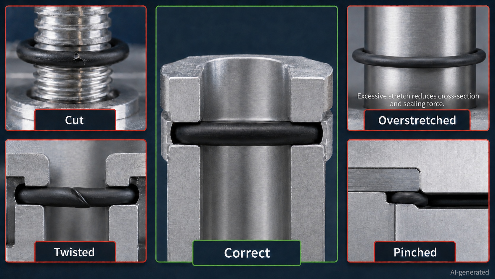
12. Common O-Ring Installation Mistakes
| Installation mistake | Likely result | Correct approach |
| Selecting by color | Wrong material installed | Verify specification and packaging |
| Measuring only the old seal | Incorrect replacement size | Check the groove, drawing and standard |
| Installing dry when lubrication is required | High friction or surface damage | Use an approved lubricant when permitted |
| Using too much grease | Contamination or blocked passages | Apply a thin, even film |
| Pulling over exposed threads | Cuts and early leakage | Use a smooth protective sleeve |
| Stretching one side heavily | Cross-section reduction or damage | Expand uniformly |
| Rolling into the groove | Twisting and spiral failure | Guide the ring into place without rolling |
| Using a screwdriver | Cut seal or scratched groove | Use a non-marring seal tool |
| Ignoring the backup ring | Extrusion under pressure | Follow the specified arrangement |
| Tightening one bolt fully first | Uneven face compression | Use a staged tightening sequence |
| Replacing the seal without inspection | Repeated failure | Check groove, surfaces, pressure and fluids |
| Reusing a removed seal | Uncertain reliability | Install a verified new O-Ring |
O-Ring Installation and Maintenance Checklist
Before closing the assembly, confirm:
· Equipment is safely isolated and depressurized.
· O-Ring size, material and hardness are correct.
· The seal is clean and free from visible defects.
· Groove and mating surfaces are clean.
· Burrs, scratches and corrosion have been checked.
· Cleaning fluid is compatible and fully removed.
· Lubricant is approved for the compound and process.
· Threads and sharp features are protected.
· The O-Ring has not been excessively stretched.
· The ring is fully seated and not twisted.
· Backup rings are installed in the correct position.
· Components are aligned before tightening.
· Fasteners are tightened evenly to specification.
· The assembly has passed its leak or functional test.
· Installation and maintenance data have been recorded where required.
Engineers replacing or specifying a seal can compare available sizes, materials and series in the JLCMC O-Ring category.
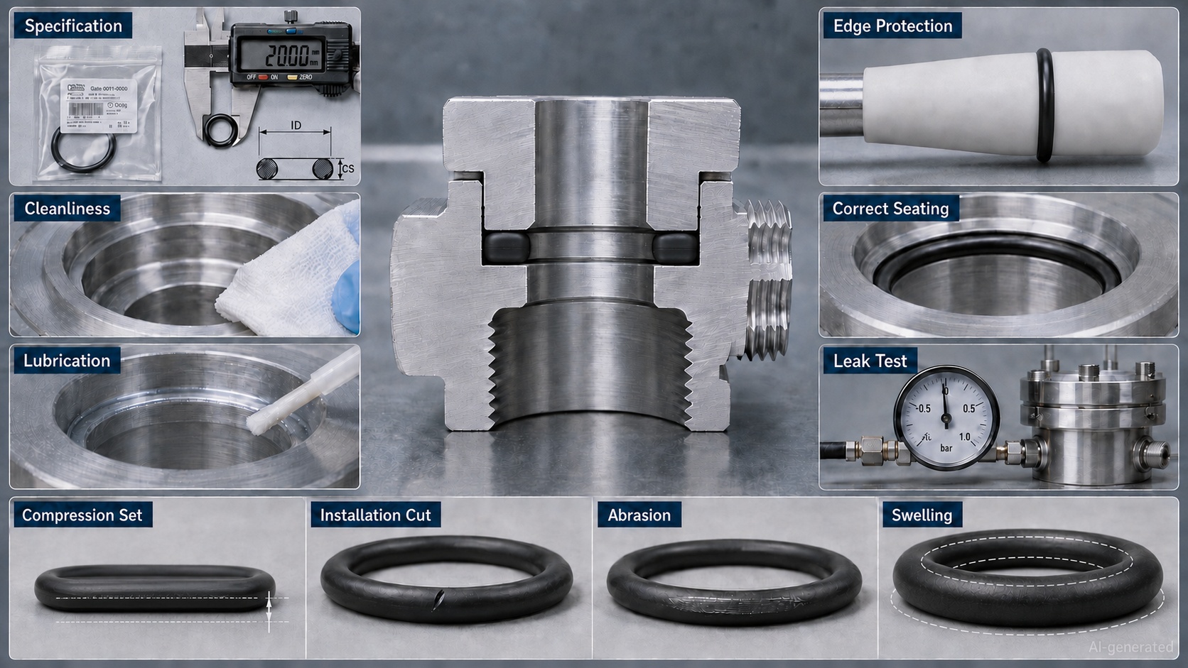
Frequently Asked Questions
Which side of an O-Ring faces outward?
A standard round O-Ring has no top, bottom or directional side. Backup rings and certain special seal profiles do have installation orientations, so the assembly drawing should be followed.
Should an O-Ring be lubricated before installation?
Usually, a thin film of compatible lubricant helps reduce installation friction. Some high-purity, dry-running or process-sensitive applications prohibit ordinary lubrication, so the equipment specification takes priority.
What is the best lubricant for an O-Ring?
There is no single best lubricant for every O-Ring. The correct product must be compatible with the elastomer, operating fluid, temperature, housing and cleanliness requirements.
Can petroleum jelly be used on an O-Ring?
Not by default. Petroleum jelly may be unsuitable for certain elastomers, fluids and cleanliness-sensitive applications. Use a documented, compatible assembly lubricant.
Can an O-Ring be installed over threads?
Yes, but the thread should be covered with a smooth installation sleeve or another approved protective aid. Pulling the seal directly across an exposed thread can cut its surface.
How much should an O-Ring stretch during installation?
Only as much as necessary to pass over the component and enter the groove. Allowable assembly elongation depends on the size, material and application. It should not be confused with the much smaller installed stretch specified by the groove design.
How can I tell whether an O-Ring is twisted?
A twisted O-Ring may look uneven, raised or spiraled in the groove. Large-diameter rings with small cross-sections are especially prone to rolling. If the position is uncertain, remove and inspect the ring before closing the assembly.
Can I use glue to keep an O-Ring in its groove?
Only when the assembly procedure explicitly approves a compatible retaining product. Adhesive can attack the elastomer, create a leakage path or prevent the ring from deforming properly.
How often should an O-Ring be replaced?
Replacement frequency depends on cycles, pressure, temperature, fluid exposure, movement and the consequences of leakage. Use inspection and operating data to establish the interval instead of applying one schedule to every application.
Why does a newly installed O-Ring leak?
Possible causes include:
· Wrong size
· Wrong material
· Surface cut
· Twisted installation
· Insufficient squeeze
· Contaminated groove
· Scratched sealing surface
· Uneven flange tightening
· Excessive clearance
· Incorrect backup-ring position
A new seal does not correct an underlying groove or hardware problem.
Conclusion
Reliable O-Ring installation depends on preparation, cleanliness and control.
Confirm the correct size and material, inspect the complete sealing path, use a compatible lubricant, protect the seal from sharp features and avoid stretching or twisting it unnecessarily. After assembly, increase pressure gradually and verify performance under realistic operating conditions.
Maintenance should look beyond visible leakage. Changes in pressure decay, air consumption, friction, cylinder speed or vacuum performance can provide early evidence that the sealing system is deteriorating.
An O-Ring is inexpensive. Reaching it after the machine has been fully assembled may be considerably less so. Installing it carefully the first time remains one of the simplest ways to improve equipment reliability.
Keep Learning
O-Ring Applications in Mechatronic Systems: Design and Selection Guide
An O-Ring in a mechatronic system does more than stop fluid from escaping. It may preserve pneumatic pressure, maintain vacuum holding force, protect a sensor from coolant, contain liquid around power electronics or keep a dispensing process repeatable. This matters because mechatronic equipment connects mechanical movement with electronics, sensors and automated control. A small sealing problem can therefore become a motion problem, a measurement problem or even a system shutdown. A leaking pneumatic......
O-Ring Material Guide: NBR, FKM, EPDM, Silicone and FFKM
Choosing an O-Ring material is not simply a choice between "rubber" and "better rubber." The seal must remain flexible, chemically stable and mechanically supported throughout the actual operating cycle. A material that performs well in mineral oil may fail in steam. Another may tolerate high temperature but become too stiff during a cold startup. Even within the same polymer family, different compounds can deliver different hardness, compression set, cleanliness and service life. This guide compares ......
O-Ring Guide: Types, Materials, Sizes and Applications
An O-Ring is a circular sealing element with a round cross-section. Installed in a properly designed groove, it is compressed between two mating surfaces to prevent liquid or gas from passing through the joint. The design could hardly be simpler, yet the O-Ring is used in everything from household fittings and automotive systems to pneumatic cylinders, vacuum equipment, industrial robots and semiconductor machinery. That small ring quietly prevents leaks, protects components and keeps pressure where i......
O-Ring Size Guide: How to Measure and Choose the Right Size
An O-Ring can have the correct material, suitable hardness and excellent chemical resistance—and still leak because its dimensions are wrong. Selecting the right O-Ring size begins with three measurements: inside diameter, cross-section and outside diameter. The arithmetic is simple. The engineering decision is not. Manufacturing tolerances, groove geometry, installation stretch, operating pressure and the condition of the old seal can all change which size is actually suitable. This O-Ring size guide......
How to Install an O-Ring Without Damaging It
Installing an O-Ring looks simple: place the ring in the groove, assemble the components and move on. In practice, many O-Ring failures begin during those few seemingly harmless seconds. A burr can cut the sealing surface. An incompatible lubricant can soften or swell the material. Excessive stretching can reduce the cross-section, while rolling the ring into the groove can create a twist that later develops into spiral failure. The frustrating part is that installation damage is not always immediatel......
O-Ring Failure Guide: Causes, Symptoms and Solutions
An O-Ring rarely fails without leaving clues. A flattened cross-section may suggest compression set. Ragged edges can point to extrusion. A soft, swollen seal often indicates chemical incompatibility, while fine surface cracks may reveal heat, ozone or environmental attack. The difficulty is that several problems can produce similar symptoms—and several causes can act together. For example, an incompatible fluid may soften an O-Ring. The softened material then becomes easier to extrude through a clear......