O-Ring Failure Guide: Causes, Symptoms and Solutions
20 min
- Key Takeaways
- 1. What Is O-Ring Failure?
- 2. Preserve the Evidence Before Inspection
- 3. O-Ring Failure Identification Chart
- 4. Compression Set and Overcompression
- 5. O-Ring Extrusion and Nibbling
- 6. Abrasion, Wear and Spiral Failure
- 7. Chemical Degradation, Swelling and Shrinkage
- 8. Heat, Ozone and Environmental Cracking
- 9. Installation Damage and Contamination
- 10. Rapid Gas Decompression
- 11. O-Ring Failure in Mechatronic Equipment
- 12. Step-by-Step O-Ring Failure Analysis
- O-Ring Failure Prevention Checklist
- Frequently Asked Questions
- Conclusion
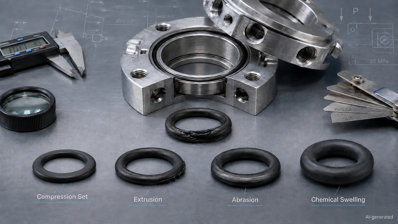
An O-Ring rarely fails without leaving clues. A flattened cross-section may suggest compression set. Ragged edges can point to extrusion. A soft, swollen seal often indicates chemical incompatibility, while fine surface cracks may reveal heat, ozone or environmental attack.
The difficulty is that several problems can produce similar symptoms—and several causes can act together.
For example, an incompatible fluid may soften an O-Ring. The softened material then becomes easier to extrude through a clearance gap. What appears to be a pressure problem may therefore begin as a material-selection problem.
Effective O-Ring failure analysis does more than identify the visible damage. It reconstructs the operating conditions that created it.
This guide explains the most common O-Ring failure modes, how to recognize them, how to investigate their root causes and how to prevent the same failure from returning.
Key Takeaways
· O-Ring appearance provides evidence, but it does not always prove a single root cause.
· Compression set, overcompression, extrusion, abrasion and chemical attack have different
corrective actions.
· A failed seal should be inspected before it is cleaned, stretched or discarded.
· The groove, mating surfaces and operating conditions are part of the sealing system and must
also be examined.
· Temperature and fluid exposure can change hardness, volume and mechanical strength.
· Installing another identical O-Ring may restore operation without solving the original problem.
· Dynamic O-Ring failures require particular attention to lubrication, alignment, surface finish and
movement.
· Corrective action should address the cause and then be validated under realistic service
conditions.
For a broader introduction to selection, dimensions and applications, begin with the O-Ring Guide: Types, Materials, Sizes and Applications.
1. What Is O-Ring Failure?
O-Ring failure occurs when the seal can no longer maintain the required separation between two pressure zones or environments.
The result is not always an obvious external leak. Depending on the system, failure may appear as:
· Loss of hydraulic pressure
· Internal pneumatic leakage
· Reduced cylinder force
· Excessive compressed-air consumption
· Slow valve response
· Vacuum loss
· Coolant leakage
· Fluid contamination
· Moisture entering an electronic enclosure
· Unstable dispensing volume
· Unexpected friction or actuator sticking
An O-Ring may also be physically damaged without leaking immediately. A partially extruded or chemically weakened seal can continue operating until a pressure peak, temperature cycle or machine restart turns minor damage into complete failure.
Failure Mode vs Root Cause
These terms should not be treated as identical:
·Failure symptom: What the machine operator observes, such as leakage or pressure loss.
·Failure mode: How the O-Ring was damaged, such as extrusion or abrasion.
·Root cause: The design, material, installation or operating condition that produced the damage.
For example:
External leakage is the symptom. Extrusion is the failure mode. Excessive clearance during a pressure peak is the root cause.
Keeping these levels separate prevents the investigation from stopping too early.
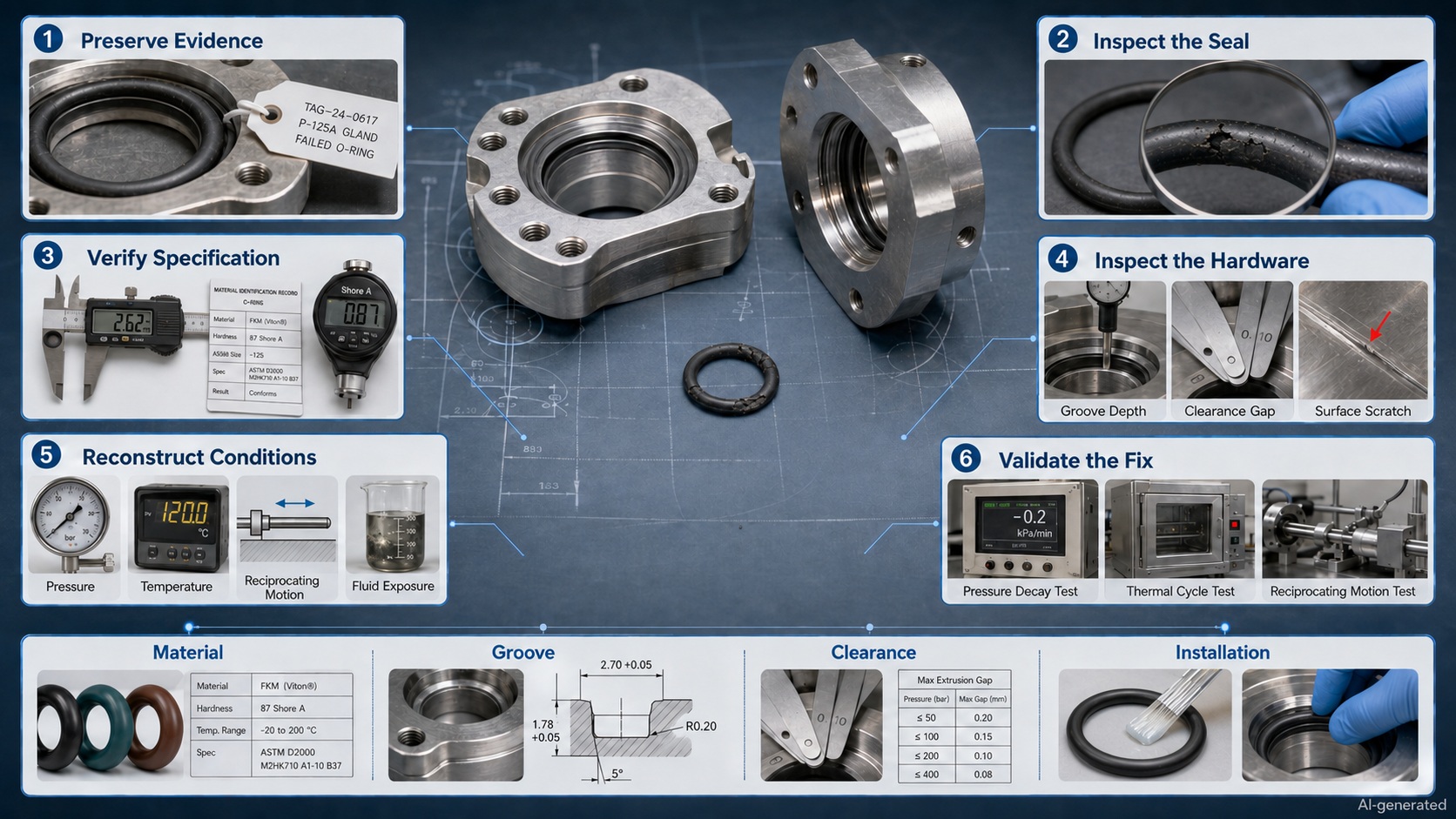
2. Preserve the Evidence Before Inspection
The first minutes after disassembly can determine whether the investigation produces useful evidence or merely a bag containing a mysterious piece of rubber.
Before removing the O-Ring, record:
· The exact leakage location
· The direction of system pressure
· Whether the leak was continuous or intermittent
· The operating temperature
· The pressure immediately before failure
· Recent maintenance or fluid changes
· Machine cycle count or service hours
· Whether the system had been restarted after a long shutdown
· Any unusual noise, vibration, friction or movement
Photograph the seal in its installed position if possible. Then photograph the groove, mating surface and O-Ring immediately after removal.
Do not stretch, wash or aggressively wipe the seal before the initial inspection. Cleaning may remove:
· Wear particles
· Chemical deposits
· Lubricant residue
· Extruded fragments
· Surface contamination
· Evidence of leakage direction
Store the failed O-Ring separately from new samples and label it with the installation position, date, machine and operating history.
3. O-Ring Failure Identification Chart
The following table provides a practical starting point. The visible symptom should guide the investigation, but it should not be treated as a final diagnosis.
| Failure mode | Typical appearance | Common causes | Corrective direction |
| Compression set | Flattened cross-section that does not recover | Excessive temperature, prolonged compression or unsuitable compound | Review material, temperature and groove squeeze |
| Overcompression | Severe flat areas or circumferential splitting | Excessive squeeze, insufficient groove volume or thermal expansion | Increase gland space and correct groove dimensions |
| Extrusion or nibbling | Ragged, bitten or torn edge, often on low-pressure side | High pressure, excessive clearance or soft material | Reduce clearance, review hardness or add backup support |
| Abrasion | Flat, polished or scraped surface | Rough surface, poor lubrication, contamination or misalignment | Improve finish, alignment, filtration and lubrication |
| Spiral failure | Diagonal or spiral cuts around the circumference | O-Ring rolling or twisting during reciprocating motion | Reduce friction, improve installation and control eccentricity |
| Chemical degradation | Cracks, blisters, discoloration, softening or tackiness | Incompatible fluid or cleaning chemical | Select a compatible compound and test all contact media |
| Swelling | Increased size, soft texture or crowded groove | Fluid absorption or chemical incompatibility | Change material and confirm sufficient gland volume |
| Shrinkage | Reduced cross-section or loss of contact | Plasticizer extraction or volatile component loss | Review compound, vacuum conditions and fluid exposure |
| Thermal degradation | Hard, brittle or cracked surface | Excessive continuous or peak temperature | Reduce temperature or choose a more suitable compound |
| Ozone cracking | Fine cracks perpendicular to the direction of stretch | Ozone, UV, outdoor exposure or unsuitable elastomer | Select an ozone-resistant material and reduce stretch |
| Installation damage | Localized cuts, nicks or slices | Burrs, threads, sharp tools or incorrect installation method | Add chamfers, sleeves and controlled assembly procedures |
| Rapid gas decompression | Blisters, pits or internal splits | Rapid pressure release after gas absorption | Slow decompression or use a resistant compound |
| Contamination damage | Embedded particles, dents or irregular wear | Dirty assembly, process debris or degraded lubricant | Improve cleaning, filtration and handling |
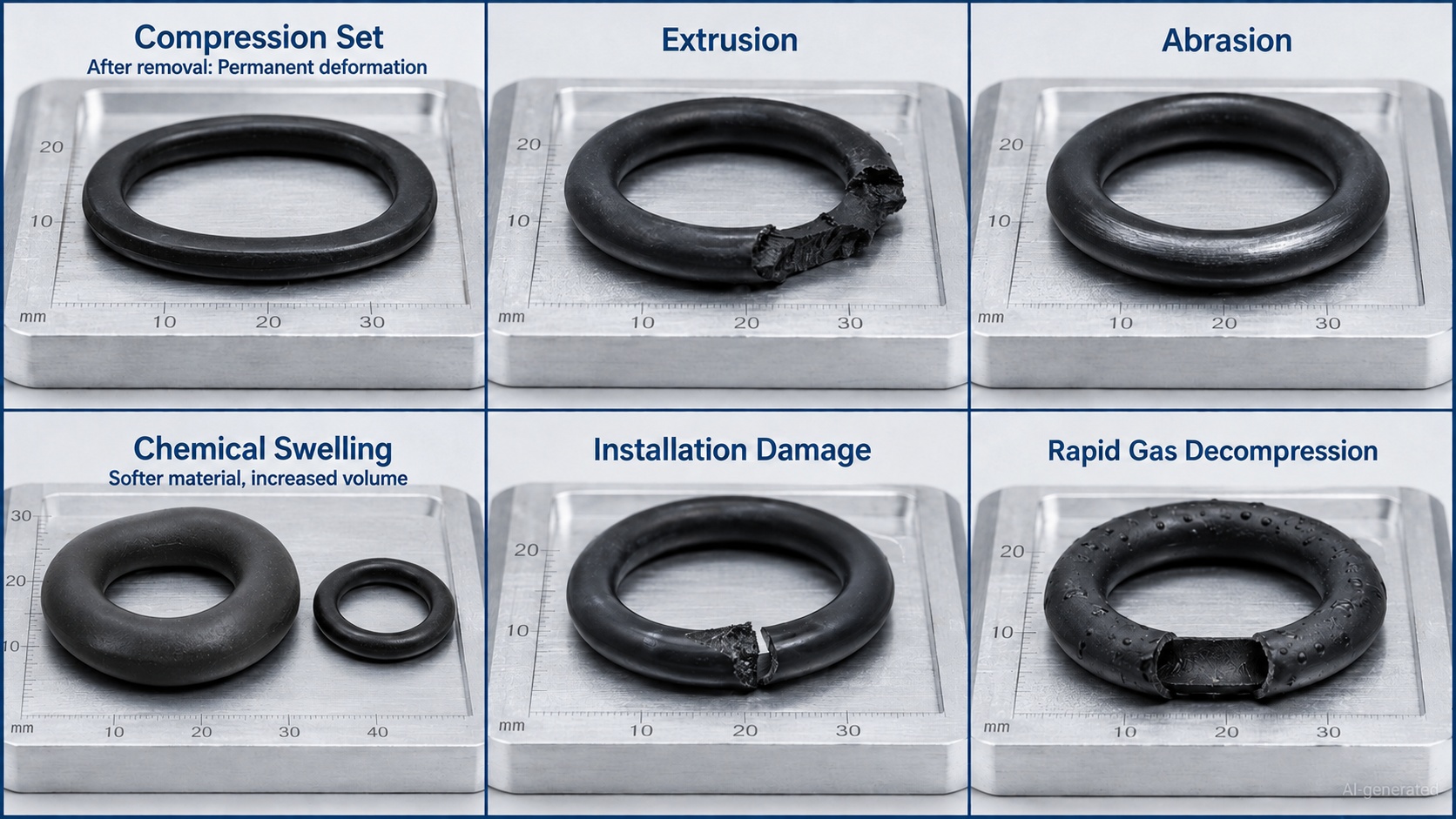
The failure classifications above align with guidance published in the Parker O-Ring Handbook and Trelleborg’s O-Ring failure reference.
4. Compression Set and Overcompression
Compression set is one of the most common causes of long-term O-Ring leakage.
What Compression Set Looks Like
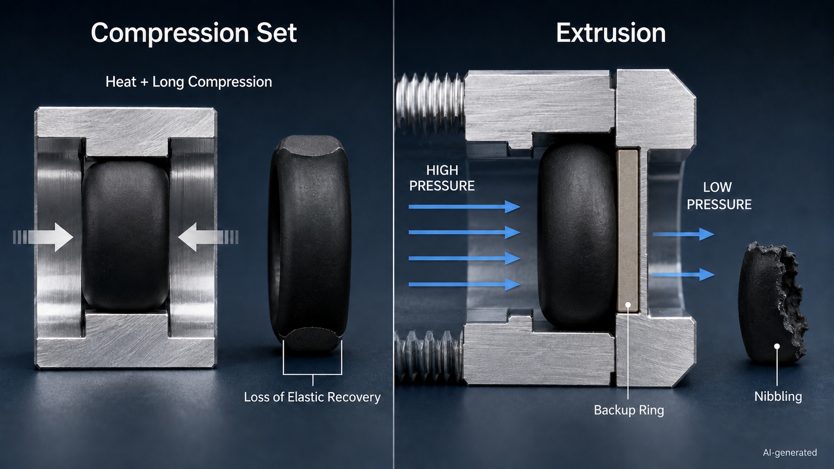
After removal, the O-Ring retains flattened surfaces corresponding to the groove and mating surface. Instead of recovering toward its original round cross-section, it remains permanently deformed.
Some flattening after service is normal. The important question is whether the seal has lost enough elastic recovery to reduce contact pressure.
Common Causes
Compression set may be caused by:
· Continuous operation above the compound’s temperature capability
· Excessive installed squeeze
· Long periods under compression
· Poor compression-set resistance
· Fluid-induced swelling
· Incorrectly cured or unsuitable compound
· Repeated thermal cycling
· Aging and oxidation
High temperature is particularly important because it accelerates permanent deformation and elastomer aging.
Compression Set vs Overcompression
Compression set describes a loss of elastic recovery. Overcompression describes an assembly condition in which the O-Ring is squeezed too severely.
An overcompressed O-Ring may show:
· Extreme flat areas
· Circumferential splitting
· Bulging into available gaps
· High assembly force
· Excessive friction
· Early permanent deformation
The groove must leave space for thermal expansion and fluid-induced swelling. If the O-Ring already occupies nearly all available volume at assembly, even moderate expansion can create damaging stress.
Corrective Actions
· Verify the O-Ring cross-section and groove depth.
· Calculate the installed squeeze.
· Check gland fill at maximum temperature and expected fluid swell.
· Confirm the actual continuous and peak temperatures.
· Select a compound with better heat and compression-set resistance.
· Reduce unnecessary squeeze.
· Improve cooling if heat comes from nearby motors, heaters or friction.
ASTM D395 provides standardized methods for evaluating rubber compression set, while ASTM D1414 provides standardized methods for testing physical properties of rubber O-rings.
Groove squeeze and gland fill are discussed in greater detail in the O-Ring Groove Design Guide.
5. O-Ring Extrusion and Nibbling
Extrusion occurs when pressure forces part of the O-Ring into the clearance between mating components.
Repeated pressure cycles can cut or tear the extruded material, producing the ragged appearance commonly called nibbling.
What Extrusion Looks Like
Typical signs include:
· Ragged or chipped edges
· Small pieces missing from one side
· A thin lip of deformed material
· Damage concentrated on the low-pressure side
· Material pressed into the clearance gap
In systems with reversing pressure, damage may occur on both sides.
Common Causes
· Excessive clearance between mating parts
· High or pulsating pressure
· Pressure spikes not included in the original design
· Eccentric shaft, piston or bore
· Soft O-Ring compound
· Material softened by heat or chemical exposure
· Excessive groove fill
· Sharp groove edges
· Component deflection under load
The clearance measured while a machine is stopped may not represent the operating clearance. Shafts bend, housings expand, cylinders breathe and plastic components deform.
Corrective Actions
· Reduce the extrusion gap.
· Review tolerance stack-up and concentricity.
· Check component deflection at peak pressure.
· Remove sharp edges at the low-pressure side.
· Select a harder or higher-strength compound where appropriate.
· Correct any chemical softening.
· Add a backup ring when required.
· Control pressure spikes and pulsation.
A harder O-Ring can improve extrusion resistance, but it cannot magically repair an oversized gap. Geometry should usually be addressed before hardness is treated as the only solution.
6. Abrasion, Wear and Spiral Failure
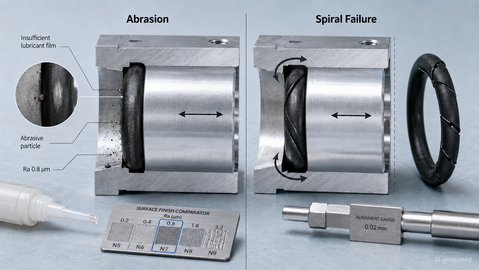
Dynamic O-Ring applications introduce friction, and friction introduces several opportunities for trouble.
Abrasion
Abrasion normally produces a flat, polished or scraped surface aligned with the direction of motion. Loose elastomer particles may also be present.
Common causes include:
· Rough shafts or bores
· Incorrect surface finish
· Poor lubrication
· Abrasive process particles
· Misalignment
· Side loading
· Excessive squeeze
· High cycle rate
· Excessive seal temperature
· Inappropriate compound wear resistance
Very rough surfaces can cut the O-Ring, while an unsuitable surface texture may also fail to retain a useful lubricant film.
Spiral Failure
Spiral failure occurs when an O-Ring rolls or twists in its groove during reciprocating movement. The resulting torsional stress produces spiral or diagonal cuts around the seal.
Common contributing factors include:
· Uneven friction around the circumference
· Poor lubrication
· Excessive groove width
· Eccentric movement
· Irregular surface finish
· Low-speed reciprocating motion
· A soft compound
· Twisting during installation
Corrective Actions
· Check rod, piston and bore alignment.
· Measure surface finish in the direction relevant to sealing motion.
· Use a compatible lubricant.
· Reduce excessive squeeze or side loading.
· Keep abrasive contaminants away from the sealing interface.
· Review groove width and dimensional tolerances.
· Consider a higher-hardness or more wear-resistant compound.
· Verify that the O-Ring is not twisted after installation.
· Consider a seal profile better suited to severe dynamic service.
If wear occurs only on one side of the O-Ring, investigate eccentricity or side loading before blaming the material.
7. Chemical Degradation, Swelling and Shrinkage
Chemical incompatibility does not always produce a dramatic melted seal. It may instead cause a gradual change in volume, hardness, strength or elasticity.
Common Symptoms
Chemically affected O-Ring products may show:
· Swelling
· Softening
· Sticky or tacky surfaces
· Discoloration
· Cracks
· Blisters
· Loss of tensile strength
· Increased hardness
· Shrinkage
· Reduced cross-section
Why Swelling Causes Leakage
Moderate swelling does not necessarily cause an immediate leak. However, excessive swelling can:
· Increase gland fill
· Raise friction
· Restrict valve or piston movement
· Weaken the material
· Promote extrusion
· Damage the seal during movement
· Prevent correct reassembly
Why Shrinkage Occurs
An O-Ring may shrink when a fluid extracts plasticizers or other compound ingredients. Similar dimensional loss may occur in high-vacuum environments or after exposure to solvents that remove soluble constituents.
Shrinkage reduces contact pressure and may create a direct leakage path.
Check Every Contact Medium
The investigation should include more than the main process fluid. Record exposure to:
· Lubricants
· Greases
· Cleaning agents
· Disinfectants
· Adhesives
· Thread-locking compounds
· Hydraulic fluids
· Coolants
· Purge gases
· Process residues
· Maintenance solvents
A seal that performs well in the process fluid may fail after being cleaned with an incompatible solvent.
ASTM D471 describes procedures for comparing how rubber compounds respond to liquid exposure. It is useful for studying changes such as volume, mass and physical properties under defined conditions. See ASTM D471: Effect of Liquids.
For detailed comparisons among NBR, FKM, EPDM, silicone and FFKM, refer to the O-Ring Material Guide.
8. Heat, Ozone and Environmental Cracking
Not all cracking is chemical attack from the sealed fluid. Heat, oxygen, ozone, UV exposure and outdoor conditions can also age an elastomer.
Thermal Degradation
An O-Ring exposed to excessive heat may become:
· Hard
· Brittle
· Glossy
· Cracked
· Permanently flattened
Possible heat sources include:
· Hot process media
· Friction in a dynamic seal
· Nearby motors
· Heaters
· Poor ventilation
· Repeated sterilization
· Unexpected machine duty cycles
Measure the temperature at the seal location rather than relying only on ambient temperature.
Ozone Cracking
Ozone damage commonly appears as fine cracks oriented perpendicular to the direction of tensile strain. It is more likely when a susceptible material is stretched and exposed to:
· Outdoor air
· UV and weathering
· Electric motors
· High-voltage equipment
· Arc-generating devices
· Ozone-producing sterilization systems
ASTM D1149 provides controlled methods for comparing the ozone-cracking resistance of vulcanized rubber. The current ASTM catalog lists D1149-18(2025) for ozone-controlled testing. ASTM rubber standards provide the current reference.
Corrective Actions
· Select a compound with suitable heat and ozone resistance.
· Minimize excessive installation stretch where applicable.
· Shield the seal from UV or ozone sources.
· Lower the local operating temperature.
· Improve cooling or ventilation.
· Confirm that temporary temperature peaks are included in the specification.
· Store spare seals away from sunlight, heat and ozone-generating equipment.
9. Installation Damage and Contamination
Installation damage usually produces localized defects rather than uniform wear.
Typical Signs
· Short cuts
· Nicks
· Slices
· Gouges
· Pinched areas
· A partially shaved surface
· Damage corresponding to a thread, port or sharp shoulder
Common Installation Errors
· Pulling the O-Ring across exposed threads
· Using sharp metal tools
· Installing through a port without a protective sleeve
· Twisting the ring
· Using an incorrect size
· Stretching it excessively
· Installing it dry when lubrication is required
· Forcing it past a sharp edge
· Pinching it between mating components
· Allowing it to leave the groove during cover assembly
A small cut can remain hidden until pressure drives it open. This is why a new O-Ring can begin leaking immediately even when its material and nominal size are correct.
Contamination
Metal chips, dust, fibers, dried sealant and process particles can create leakage paths or become embedded in the elastomer.
Contamination may also cause misleading evidence. Hard particles can produce local dents, scratches or abrasion that resemble material weakness.
Corrective Actions
· Add lead-in chamfers and radiused edges.
· Deburr holes, ports and grooves.
· Cover exposed threads during assembly.
· Use non-sharp installation tools.
· Apply a compatible lubricant where permitted.
· Clean the groove and surrounding work area.
· Use controlled fixtures for repetitive assembly.
· Confirm the seal is seated before tightening the housing.
· Train operators to identify twisting and pinching.
A complete assembly procedure is available in How to Install an O-Ring Without Damaging It.
10. Rapid Gas Decompression
Rapid gas decompression—also called explosive decompression—can occur when an elastomer is exposed to high-pressure gas.
Gas diffuses into the O-Ring while the system is pressurized. If pressure is released faster than the gas can escape from the material, the expanding gas may form internal bubbles and ruptures.
Typical Appearance
· Surface blisters
· Pits or pocks
· Internal splits
· Ruptured bubbles
· Damage visible only after the seal is cut open
Risk Factors
· High gas pressure
· Long exposure time
· Rapid depressurization
· Large O-Ring cross-section
· High gas solubility in the compound
· Elevated temperature
· Compound structure and hardness
· Repeated pressure cycling
Corrective Actions
· Reduce the decompression rate.
· Use controlled pressure-release stages.
· Select a compound tested for decompression resistance.
· Review the O-Ring cross-section.
· Reduce operating temperature where practical.
· Validate performance through representative pressure cycles.
Hardness alone does not define decompression resistance. The complete compound formulation and gas exposure must be considered.
11. O-Ring Failure in Mechatronic Equipment
In mechatronic systems, the machine-level symptom may appear far from the actual seal.
| Equipment | Possible O-Ring failure symptom | Inspection priorities |
| Pneumatic cylinder | Reduced force, creeping or inconsistent speed | Bore wear, lubrication, piston alignment and seal abrasion |
| Solenoid valve | Slow response or internal bypass leakage | Small seal damage, contamination and chemical compatibility |
| Vacuum gripper | Low holding force or dropped workpiece | Compression set, surface scratches and housing flatness |
| Sensor enclosure | Moisture ingress or corrosion | Face-seal squeeze, cover deflection and installation damage |
| Robotic end effector | Unstable pneumatic operation | Vibration, tubing pressure and seal movement |
| Automated dispenser | Inaccurate dosing or cross-contamination | Chemical swelling, wear and cleaning-fluid exposure |
| Liquid-cooling module | Coolant loss or electronics alarm | Coolant compatibility, thermal cycling and fitting alignment |
| Precision pump | Flow drift or inability to prime | Small O-Ring dimensions, contamination and surface defects |
Automated equipment may also hide early failure. A pressure regulator, control loop or pump can temporarily compensate for leakage, making the system appear functional while energy consumption or cycle time gradually increases.
For application-specific examples, see O-Ring Applications in Mechatronic Systems.
12. Step-by-Step O-Ring Failure Analysis
A consistent investigation process is more reliable than selecting a failure mode from appearance alone.
Step 1: Define the Failure Symptom
Record exactly what changed:
· External leakage
· Internal bypass
· Reduced pressure
· Increased friction
· Vacuum loss
· Slow response
· Contamination
· Moisture ingress
Note when the symptom occurs: startup, full pressure, high temperature, movement, shutdown or decompression.
Step 2: Confirm the O-Ring Specification
Verify:
· Inside diameter
· Cross-section
· Material family
· Exact compound
· Hardness
· Size standard
· Supplier and batch
· Storage history
· Installation date
Do not identify the material from color alone.
If dimensional verification is needed, use the O-Ring Size Guide. Measure the groove and mating components rather than relying entirely on the distorted dimensions of a failed seal.
Step 3: Inspect the Seal Without Cleaning It
Examine the complete circumference under good lighting and magnification.
Record:
· Damage location
· Pressure-side orientation
· Surface texture
· Deposits
· Missing material
· Changes in color
· Localized versus uniform damage
Step 4: Inspect the Hardware
Check:
· Groove depth and width
· Clearance gaps
· Burrs and sharp edges
· Surface finish
· Scratches across the sealing path
· Corrosion
· Housing flatness
· Shaft or bore concentricity
· Component deflection
· Fastener torque and spacing
A flawless replacement O-Ring will still leak if the sealing surface contains a scratch that crosses the entire contact band.
Step 5: Reconstruct the Operating Conditions
Compare the original design assumptions with actual service:
· Continuous and peak pressure
· Pressure direction
· Decompression rate
· Minimum and maximum temperature
· Cycle speed
· Stroke length
· Vibration
· Fluid composition
· Lubrication
· Cleaning procedures
· Maintenance history
Step 6: Look for Interacting Causes
Consider whether one problem created another:
· Chemical swelling increased gland fill.
· Heat softened the material and promoted extrusion.
· Misalignment caused uneven abrasion.
· Contamination damaged the surface and removed lubrication.
· Overcompression increased friction and operating temperature.
Step 7: Compare With a Known Good Sample
Compare the failed seal with:
· An unused O-Ring from the same batch
· A seal from a functioning machine
· The supplier’s drawing
· Original material data
· Previous failure records
Dimensional change, hardness change and surface appearance are easier to interpret when a valid reference is available.
Step 8: Select Corrective Action
Corrective action may involve:
· A different size
· A redesigned groove
· Lower squeeze
· Reduced clearance
· A different material or compound
· Improved surface finish
· Better alignment
· A backup ring
· Improved lubrication
· A controlled decompression rate
· A revised installation process
Once the application requirements are confirmed, suitable sizes and materials can be compared in the JLCMC O-Ring category.
Step 9: Validate the Fix
Test the revised assembly under realistic pressure, temperature, motion, fluid exposure and cleaning cycles.
A successful bench test at room temperature does not prove that the seal will survive a hot, vibrating machine after several thousand cycles.
O-Ring Failure Prevention Checklist
Before releasing or repairing an O-Ring assembly, confirm:
· The material is compatible with every contact fluid.
· Continuous and peak temperatures are within the compound’s capability.
· ID and cross-section match the drawing.
· Groove dimensions provide suitable squeeze and gland volume.
· Operating clearance is controlled.
· Pressure spikes and decompression rates are understood.
· Dynamic surfaces have the required finish.
· Shafts, pistons and bores are aligned.
· Lubricant is compatible with the seal and process.
· Threads and sharp edges are protected during assembly.
· The O-Ring is not twisted or pinched.
· The groove is clean and free of debris.
· Housing stiffness and fastener spacing maintain uniform compression.
· Validation testing represents real service conditions.
· Failed seals and corrective actions are documented.
Frequently Asked Questions
Why does an O-Ring become flat?
An O-Ring may remain flat because of compression set caused by prolonged compression, excessive heat, too much squeeze or an unsuitable compound. Some temporary flattening is normal, so recovery and leakage history should also be evaluated.
Why does an O-Ring leak immediately after replacement?
Possible causes include the wrong size, installation cuts, twisting, contamination, an empty or oversized groove, inadequate squeeze, damaged hardware or an incompatible replacement material.
What causes an O-Ring to swell?
Swelling normally occurs when the elastomer absorbs a fluid. Excessive swelling indicates that the compound is not sufficiently compatible with the process fluid, lubricant, cleaner or another contact chemical.
What causes pieces to break off an O-Ring?
Ragged pieces missing from an edge often indicate extrusion or nibbling. Brittle fragments may instead suggest thermal or chemical degradation. The damage location and material condition help distinguish them.
How can I tell whether an O-Ring has been extruded?
Extrusion usually produces a thin, deformed lip or ragged damage on the low-pressure side. Inspect the corresponding clearance gap and check whether pressure, eccentricity or component deflection exceeded the design assumptions.
Can a harder O-Ring stop extrusion?
A harder compound may improve extrusion resistance, but it cannot fully compensate for excessive clearance, sharp groove edges or severe component deflection. Geometry and pressure conditions must also be corrected.
Why does an O-Ring twist in a cylinder?
Uneven friction, insufficient lubrication, excessive groove width, eccentric movement or twisting during installation can cause an O-Ring to roll in a reciprocating groove and develop spiral failure.
Can a failed O-Ring identify the wrong material?
Its condition can suggest chemical or thermal incompatibility, but appearance alone rarely identifies the exact elastomer. Supplier records, compound data and controlled exposure tests provide stronger evidence.
Should a failed O-Ring be reused for testing?
It may be retained for inspection and comparison, but it should not normally be returned to critical service. Removal can stretch or damage it, and its sealing capability may already be reduced.
Should every leaking O-Ring be replaced with a different material?
No. Leakage may result from size, groove geometry, clearance, surface finish, installation or movement. Material should be changed only when the investigation supports that corrective action.
Conclusion
O-Ring failure analysis begins with the visible damage but should not end there.
Compression set points toward lost elastic recovery. Ragged edges suggest extrusion. Polished wear indicates abrasion. Swelling or softening raises questions about chemical compatibility, while blisters after high-pressure gas service may indicate rapid gas decompression.
Each of these observations is evidence—not a complete verdict.
A reliable investigation examines the O-Ring, groove, mating surfaces, operating conditions, fluid exposure and assembly process as one sealing system. The most effective corrective action removes the root cause and is then tested under realistic service conditions.
Replacing the seal is maintenance. Understanding why it failed is engineering.
Keep Learning
O-Ring Applications in Mechatronic Systems: Design and Selection Guide
An O-Ring in a mechatronic system does more than stop fluid from escaping. It may preserve pneumatic pressure, maintain vacuum holding force, protect a sensor from coolant, contain liquid around power electronics or keep a dispensing process repeatable. This matters because mechatronic equipment connects mechanical movement with electronics, sensors and automated control. A small sealing problem can therefore become a motion problem, a measurement problem or even a system shutdown. A leaking pneumatic......
O-Ring Material Guide: NBR, FKM, EPDM, Silicone and FFKM
Choosing an O-Ring material is not simply a choice between "rubber" and "better rubber." The seal must remain flexible, chemically stable and mechanically supported throughout the actual operating cycle. A material that performs well in mineral oil may fail in steam. Another may tolerate high temperature but become too stiff during a cold startup. Even within the same polymer family, different compounds can deliver different hardness, compression set, cleanliness and service life. This guide compares ......
O-Ring Guide: Types, Materials, Sizes and Applications
An O-Ring is a circular sealing element with a round cross-section. Installed in a properly designed groove, it is compressed between two mating surfaces to prevent liquid or gas from passing through the joint. The design could hardly be simpler, yet the O-Ring is used in everything from household fittings and automotive systems to pneumatic cylinders, vacuum equipment, industrial robots and semiconductor machinery. That small ring quietly prevents leaks, protects components and keeps pressure where i......
O-Ring Size Guide: How to Measure and Choose the Right Size
An O-Ring can have the correct material, suitable hardness and excellent chemical resistance—and still leak because its dimensions are wrong. Selecting the right O-Ring size begins with three measurements: inside diameter, cross-section and outside diameter. The arithmetic is simple. The engineering decision is not. Manufacturing tolerances, groove geometry, installation stretch, operating pressure and the condition of the old seal can all change which size is actually suitable. This O-Ring size guide......
How to Install an O-Ring Without Damaging It
Installing an O-Ring looks simple: place the ring in the groove, assemble the components and move on. In practice, many O-Ring failures begin during those few seemingly harmless seconds. A burr can cut the sealing surface. An incompatible lubricant can soften or swell the material. Excessive stretching can reduce the cross-section, while rolling the ring into the groove can create a twist that later develops into spiral failure. The frustrating part is that installation damage is not always immediatel......
O-Ring Failure Guide: Causes, Symptoms and Solutions
An O-Ring rarely fails without leaving clues. A flattened cross-section may suggest compression set. Ragged edges can point to extrusion. A soft, swollen seal often indicates chemical incompatibility, while fine surface cracks may reveal heat, ozone or environmental attack. The difficulty is that several problems can produce similar symptoms—and several causes can act together. For example, an incompatible fluid may soften an O-Ring. The softened material then becomes easier to extrude through a clear......