O-Ring Guide: Types, Materials, Sizes and Applications
21 min
- Key Takeaways
- 1. What Is an O-Ring?
- 2. How Does an O-Ring Work?
- 3. Main Types of O-Ring Application
- 4. Common O-Ring Materials
- 5. O-Ring Size Basics
- 6. O-Ring Standards and Size Systems
- 7. How O-Ring Hardness Affects Performance
- 8. O-Ring Groove Design Basics
- 9. Common O-Ring Applications
- 10. O-Ring Applications in Mechatronic Systems
- 11. How to Choose the Right O-Ring
- 12. O-Ring Installation and Failure Prevention
- Frequently Asked Questions
- Conclusion
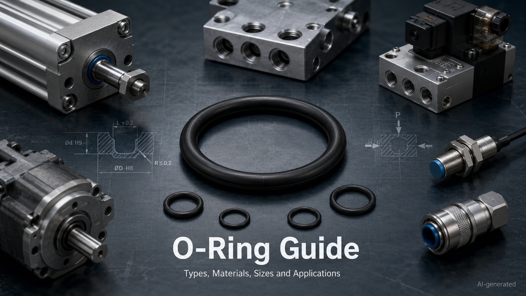
An O-Ring is a circular sealing element with a round cross-section. Installed in a properly designed groove, it is compressed between two mating surfaces to prevent liquid or gas from passing through the joint.
The design could hardly be simpler, yet the O-Ring is used in everything from household fittings and automotive systems to pneumatic cylinders, vacuum equipment, industrial robots and semiconductor machinery. That small ring quietly prevents leaks, protects components and keeps pressure where it belongs—not bad for a part that usually disappears the moment a machine is assembled.
Choosing the right O-Ring, however, takes more than matching the diameter. Material compatibility, operating temperature, pressure, movement, hardness and groove geometry all affect sealing performance.
This guide introduces the main O-Ring types, materials, sizes, standards and applications, with additional attention given to industrial automation and mechatronic equipment.
Key Takeaways
· An O-Ring is generally specified by its inside diameter and cross-section.
· Outside diameter can be calculated as OD = ID + 2 × CS.
· O-Ring size, material and hardness are separate selection decisions.
· NBR, FKM, EPDM, silicone and FFKM are not interchangeable.
· Static and dynamic seals have different groove, friction and wear requirements.
· A correctly sized O-Ring still needs a properly designed groove.
· Material compatibility must be checked against the actual fluid, temperature and operating conditions.· In mechatronic equipment, a small seal failure can cause pressure loss, unstable movement, contamination or inaccurate operation.
1. What Is an O-Ring?
An O-Ring is an elastomeric sealing element with a circular cross-section, designed to prevent leakage between mating surfaces. Its circular cross-section allows it to deform when installed between two mating components.
A standard O-Ring is defined by three basic dimensions:
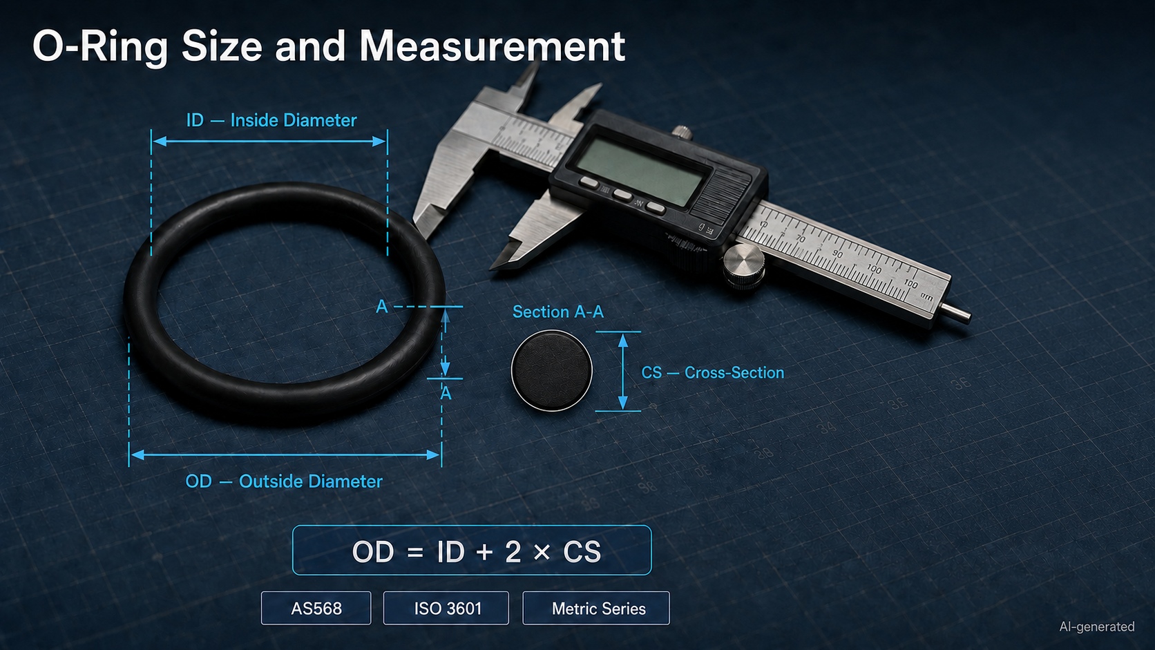
· Inside Diameter (ID): the diameter of the central opening
· Cross-Section (CS): the thickness of the ring
· Outside Diameter (OD): the total diameter measured across the exterior
Although most O-Ring products look similar, their performance can differ substantially. Two rings with identical dimensions may behave very differently if they are made from different materials or have different hardness levels.
An O-Ring can be designed to seal:
· Water
· Compressed air
· Hydraulic oil
· Lubricant
· Fuel
· Refrigerant
· Vacuum
· Process chemicals
· Dust and moisture
A conventional O-Ring has a round cross-section. X-rings, square rings, D-rings and lip seals are related sealing products, but they should not automatically be treated as interchangeable O-Ring alternatives.
2. How Does an O-Ring Work?
An O-Ring works through controlled elastic deformation.
When the mating components are assembled, the ring is squeezed between the groove and the opposing sealing surface. This initial compression closes the potential leakage path.
When pressure enters the system, it pushes the elastomer toward the low-pressure side of the groove. Contact between the O-Ring and the sealing surfaces increases, helping the seal respond to system pressure.
Three conditions are necessary for reliable sealing:
1.The O-Ring must have enough initial compression.
2.The groove must provide space for deformation and material expansion.
3.The clearance gap must be controlled to prevent extrusion.
Too little compression may allow leakage. Too much compression can increase friction, heat, assembly force and permanent deformation.
The groove should not be completely filled with elastomer. The O-Ring needs room to deform under pressure and may expand after absorbing an operating fluid. Giving the seal no room to move is rather like putting on hiking boots two sizes too small—the problem may not appear immediately, but the journey is unlikely to end well.
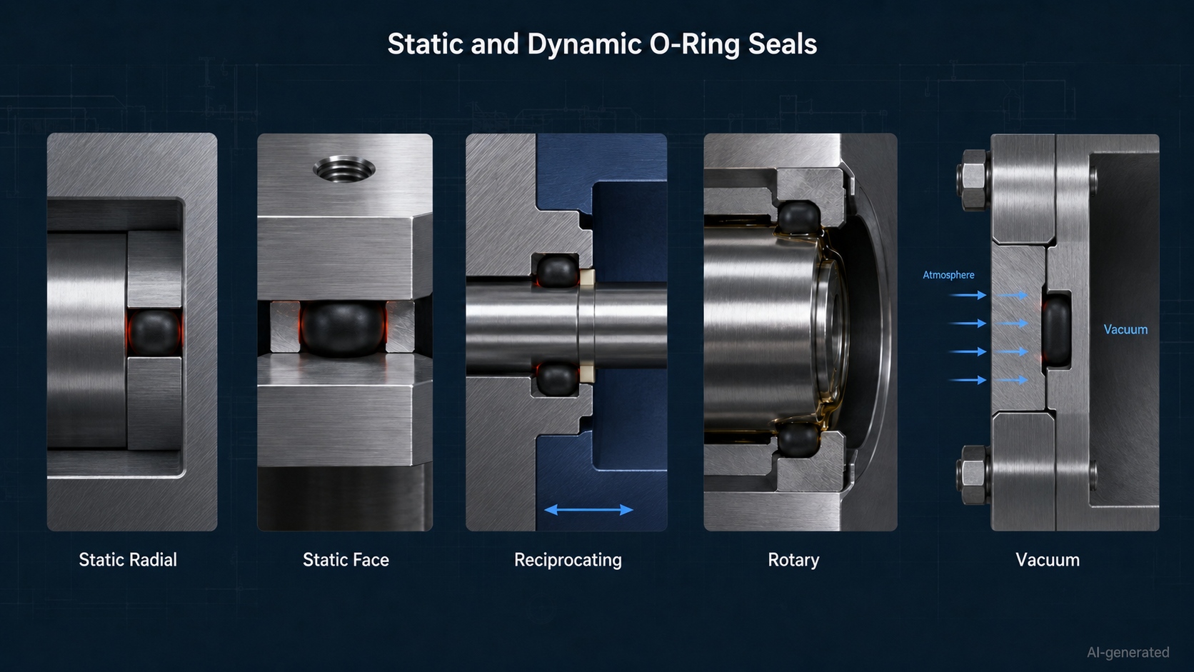
Static vs Dynamic O-Ring Sealing
| Seal condition | Relative movement | Typical applications |
| Static | No movement across the sealing interface | Covers, flanges, fittings and sensor housings |
| Reciprocating | Linear back-and-forth movement | Pneumatic cylinders, hydraulic pistons and dosing equipment |
| Rotary | Continuous or intermittent rotation | Slow shafts and selected rotary fittings |
| Oscillating | Limited angular movement | Rotary actuators, linkages and valve mechanisms |
| Vacuum | Prevents external gas from entering a low-pressure chamber | Vacuum grippers, pumps and processing equipment |
Static sealing is generally easier because there is no continuous rubbing at the contact surface. Dynamic sealing requires closer attention to friction, lubrication, heat, surface finish and wear.
A standard O-Ring can sometimes handle slow rotary movement. Continuous high-speed rotation usually requires a dedicated rotary shaft seal.
3. Main Types of O-Ring Application
O-Ring types are commonly classified according to their installation direction and operating movement.
Static Radial O-Ring
A static radial seal is compressed between an inner and outer cylindrical surface. It is commonly used in plugs, fittings, valve cartridges and stationary tube connections.
Static Face O-Ring
A face seal is installed in a groove on one flat surface and compressed axially by another surface. Typical applications include covers, flanges, manifolds, pump housings and electronic enclosures.
Reciprocating O-Ring
A reciprocating O-Ring seals a piston or rod that moves linearly. Pneumatic and hydraulic cylinders are familiar examples. Low friction, lubrication, surface finish and wear resistance are particularly important.
Rotary O-Ring
A rotary O-Ring seals a shaft that turns relative to the seal. It is most appropriate for limited-speed, well-lubricated applications. Excessive rotational speed can generate friction and heat.
Vacuum O-Ring
A vacuum O-Ring limits gas leakage into a low-pressure chamber. Material permeability, outgassing, surface condition, joint cleanliness and compatible vacuum grease may all affect performance.
Port and Boss O-Ring
An O-Ring may seal straight-thread ports, plugs and fluid connectors. The thread provides mechanical retention, while the O-Ring provides the primary seal.
Small O-Ring
A small-inner-diameter O-Ring is used in miniature valves, compact pneumatic components, sensors, test fixtures, precision pumps and small fluid connectors.
As the dimensions become smaller, flash, surface defects, dimensional tolerances and installation scratches become more significant.
4. Common O-Ring Materials
O-Ring material selection should begin with the operating medium, but it should also consider temperature, pressure, movement, exposure time, lubrication and environmental conditions.
| Material | Main strengths | Common applications | Important limitations |
| NBR | Good resistance to mineral oils, grease and many hydraulic fluids | Hydraulic systems, pneumatic equipment and general machinery | Limited resistance to ozone, weathering and some high-temperature environments |
| FKM | Strong high-temperature performance and broad resistance to oils, fuels and many chemicals | Pumps, valves, vacuum equipment and process machinery | Not universally compatible with steam, hot water, amines or certain polar fluids |
| EPDM | Good resistance to water, steam, ozone and outdoor exposure | Water systems, cleaning equipment and cooling circuits | Generally unsuitable for mineral oils and petroleum-based fuels |
| Silicone | Flexible across a broad temperature range | Electronic equipment, sensor housings and static seals | Lower tear and abrasion resistance can limit dynamic use |
| HNBR | Better heat, oxidation and wear resistance than conventional NBR | Automotive systems and demanding industrial equipment | Higher cost than standard NBR |
| FFKM | Exceptional resistance to aggressive chemicals and extreme environments | Semiconductor, chemical-processing, vacuum and high-purity equipment | High cost and compound-specific mechanical properties |
| PTFE | Broad chemical resistance and low friction | Specialty chemical and high-temperature sealing | Limited elasticity requires specialized design |
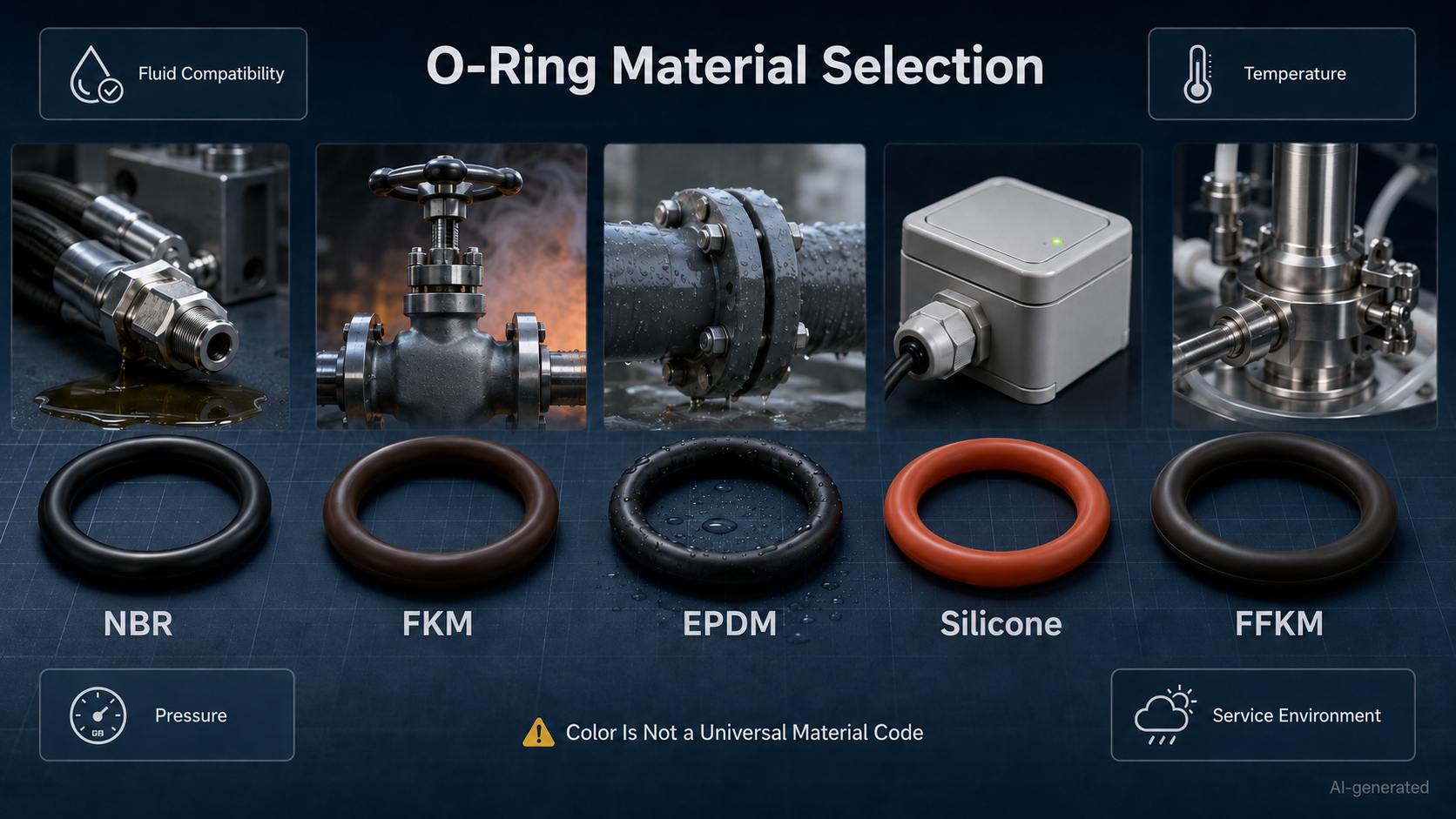
FKM is sometimes casually called Viton®, but Viton is a trade name, while FKM is the generic material designation.
Color is not a universal material code either. A brown O-Ring may be FKM in one supplier’s catalog, but color alone should never replace a material specification.
Why the Exact Compound Matters
Two NBR compounds can have different hardness, low-temperature flexibility, compression-set behavior and fuel resistance. The same applies to FKM, EPDM and other material families.
Final selection should consider:
· Complete fluid composition
· Minimum and maximum temperature
· Continuous and peak pressure
· Static or dynamic operation
· Cleaning and sterilization chemicals
· Lubricant compatibility
· Required service life
· Outdoor, ozone or UV exposure
· Regulatory and cleanliness requirements
For a detailed comparison of material compatibility, temperature capability, hardness and typical uses, see the O-Ring Material Guide: NBR, FKM, EPDM, Silicone and FFKM.
5. O-Ring Size Basics
An O-Ring size is usually defined by its inside diameter and cross-section.
The relationship between the three dimensions is:
OD=ID+2(CS)
If the inside and outside diameters are known, the cross-section can be estimated using:

For example, an O-Ring with a 10 mm inside diameter and a 2 mm cross-section has a nominal outside diameter of:
10+2(2)=14 mm
How to Measure an O-Ring
For an unused O-Ring:
1.Place it on a clean, flat surface.
2.Measure the inside diameter without stretching it.
3.Measure the cross-section at several locations.
4.Calculate or confirm the outside diameter.
5.Compare the results with the relevant size chart and tolerance.
A digital caliper is suitable for many general-purpose sizes. Optical equipment, gauges or specialist measuring tools may be required for miniature or close-tolerance products.
Measuring an old seal is less reliable. Heat, swelling, compression set, chemical exposure and stretching can permanently change its dimensions. When possible, measure the groove and check the original equipment drawing instead of treating a worn O-Ring as a perfect reference.
Detailed measurement methods, formulas and size-selection examples are available in the O-Ring Size Guide: How to Measure and Choose the Right Size.
6. O-Ring Standards and Size Systems
Standardized sizes simplify design, replacement and purchasing. However, not every size designation belongs to the same dimensional system.
AS568
SAE AS568F specifies inside diameters, cross-sections, tolerances and dash-number identification codes for O-Ring sealing applications and straight-thread tube-fitting boss gaskets.
An AS568 dash number identifies a defined size. It does not specify the material, hardness or complete compound.
ISO 3601
ISO 3601-1 covers inside diameters, cross-sections, tolerances and designation codes for general industrial and aerospace O-Ring applications.
ISO 3601-2 covers housing dimensions for general applications, including selected hydraulic and pneumatic piston and rod arrangements.
Metric and Regional Series
Metric O-Ring products may follow ISO dimensions, national standards, regional series or supplier-specific catalogs. Similar nominal dimensions do not automatically make two products interchangeable.
The JLCMC O-Ring category includes National Standard, P, S, G, V, AS and small-inner-diameter series. These labels should always be matched against the individual product drawing and size table.
An “AS Series” catalog name, for example, should not automatically be interpreted as an AS568 dash number unless the technical data confirms the relationship.
Before replacing one series with another, compare:
· Inside diameter
· Cross-section
· Dimensional tolerance
· Groove dimensions
· Material
· Hardness
· Static or dynamic operating state
· Pressure and movement conditions
“Nearly the same size” and “technically interchangeable” are not synonyms.
7. How O-Ring Hardness Affects Performance
O-Ring hardness is commonly measured on the Shore A scale. A lower value indicates a softer material, while a higher value indicates a harder material.
| Approximate hardness | General behavior | Typical considerations |
| 45–65 Shore A | Softer and easier to deform | Good conformity at low pressure, but lower extrusion resistance |
| 70–75 Shore A | Balanced general-purpose range | Common in industrial static and dynamic applications |
| 85–90 Shore A | Harder and more resistant to extrusion | Useful under higher pressure, but requires greater assembly force |
A softer O-Ring conforms more easily to small surface irregularities. A harder compound generally provides better resistance to extrusion and mechanical damage.
However, a harder O-Ring is not automatically a better high-pressure seal. Pressure capability also depends on:
· Clearance gap
· Groove support
· Cross-section
· Operating temperature
· Pressure cycling
· Material strength
· Use of a backup ring
O-Ring hardness should be evaluated together with material compatibility, pressure, clearance and sealing movement. A harder compound may improve extrusion resistance, but it cannot compensate for an oversized clearance gap or an incorrectly designed groove.
8. O-Ring Groove Design Basics
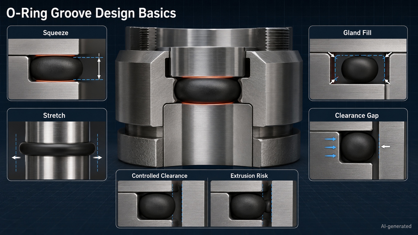
The groove controls how the O-Ring is compressed, supported and allowed to deform. A correctly sized seal can still fail in an incorrectly designed groove.
Squeeze
Squeeze is the reduction in cross-sectional height after assembly. It creates the initial sealing contact.
Insufficient squeeze may cause leakage. Excessive squeeze can increase friction, heat, assembly force and compression set.
Stretch
An O-Ring installed over a piston or male component is normally stretched slightly. Excessive stretch reduces the cross-section and changes the available squeeze.
Gland Fill
The O-Ring should not completely fill the groove. Space is required for thermal expansion, pressure-driven deformation and possible fluid-induced swelling.
Clearance Gap
Under pressure, the elastomer may be pushed into the gap between mating components. Excessive clearance can cause extrusion or nibbling.
A harder compound or backup ring may improve support, but reducing the unsupported gap is often the more effective starting point.
Surface Finish
Dynamic sealing surfaces must be smooth enough to limit wear while retaining an appropriate lubricant film. Scratches running across the sealing path may act as miniature leakage channels.
Groove Edges
Burrs, sharp edges and exposed threads can cut the seal during installation. Chamfers, radiused edges and installation sleeves help protect the O-Ring.
Static face seals, piston seals, rod seals and rotary seals should not share the same groove dimensions simply because they all use a round seal. The O-Ring Groove Design Guide: Squeeze, Stretch and Gland Fill provides a more detailed design process.
9. Common O-Ring Applications
The O-Ring is used across many industries because it is compact, economical and available in a broad range of materials and dimensions.
Hydraulic Equipment
Hydraulic cylinders, manifolds, pumps and valves use O-Ring seals to retain hydraulic fluid under pressure. Oil compatibility, extrusion resistance and pressure cycling are central considerations.
Pneumatic Equipment
Pneumatic cylinders, directional valves, regulators and fittings rely on O-Ring seals to control compressed air. Low friction becomes especially important when smooth movement and fast response are required.
Pumps and Fluid-Control Systems
Pump housings, cartridges, ports and valve bodies use static or dynamic seals. Material selection depends on the pumped medium, temperature and cleaning process.
Automotive and Mobile Equipment
Fuel systems, engines, transmissions, braking equipment and thermal-management systems use O-Ring seals. Each fluid requires a compatible compound; “automotive grade” is not a complete material specification.
Water and HVAC Systems
Pipes, valves, heat exchangers and cooling circuits may use EPDM or another water-compatible compound. Lubricants, refrigerants and water-treatment chemicals must also be considered.
Chemical and Vacuum Equipment
Aggressive chemicals and low-pressure environments may require FKM, FFKM or another specialty compound. Permeability, outgassing, cleanliness and decompression behavior may be as important as ordinary fluid resistance.
Food, Medical and High-Purity Equipment
Material compatibility is only one requirement. The selected compound may also need appropriate regulatory, cleanliness, extraction and traceability documentation.
10. O-Ring Applications in Mechatronic Systems
Mechatronic equipment combines mechanical movement, electronics, sensors and automated control. An O-Ring failure can therefore cause consequences beyond a visible leak.
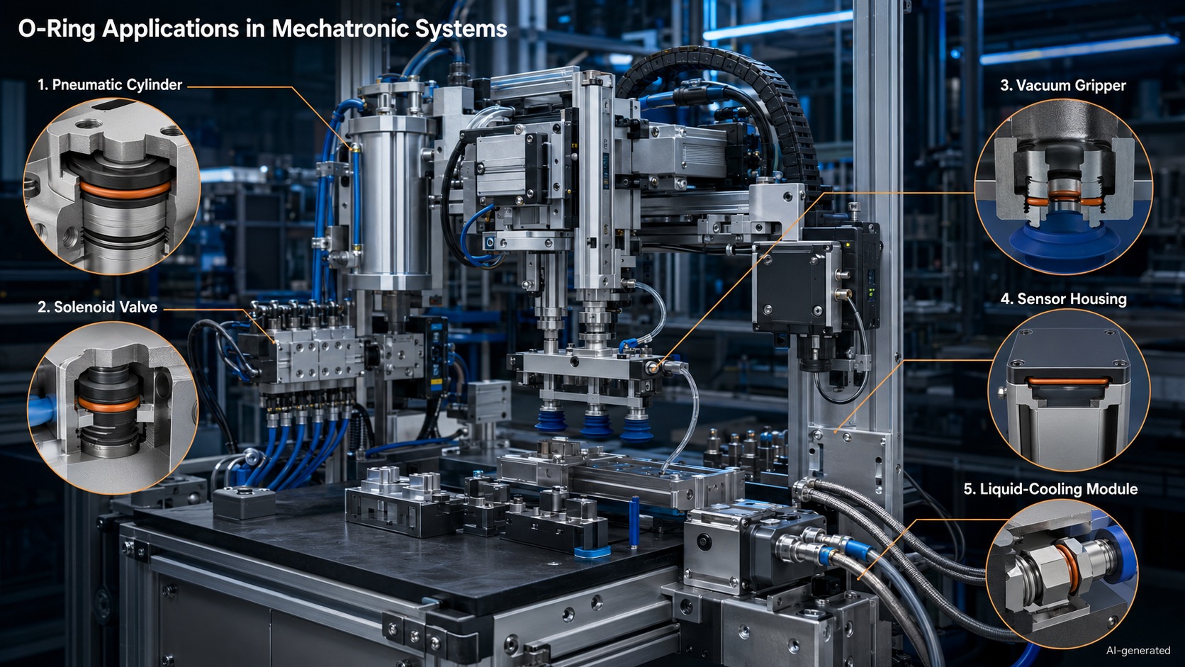
| Mechatronic component | O-Ring function | Main selection priorities |
| Pneumatic cylinder | Seals pistons, rods and end caps | Friction, wear, lubrication and cycle rate |
| Solenoid valve | Seals cartridges, ports and manifolds | Small dimensions, response speed and media compatibility |
| Vacuum gripper | Prevents air from entering the vacuum circuit | Permeability, compression set and surface condition |
| Sensor housing | Blocks water, coolant, oil and dust | Static squeeze, environmental resistance and housing stiffness |
| Robotic end effector | Seals pneumatic or fluid channels | Vibration, movement, maintenance and media compatibility |
| Automated dispenser | Contains adhesive, lubricant or process fluid | Chemical compatibility, cleaning agents and dosing pressure |
| Liquid-cooling module | Seals pumps, fittings and cold plates | Coolant compatibility and temperature cycling |
| Precision pump | Seals miniature fluid passages | Dimensional tolerance, cleanliness and chemical resistance |
Pneumatic Cylinders and Valves
A leaking piston seal can reduce available thrust and make cylinder movement inconsistent. Internal valve leakage may slow response, reduce efficiency or increase compressed-air consumption.
Dynamic O-Ring selection for pneumatic equipment must balance sealing contact against friction. Excessive squeeze may increase breakaway force, while insufficient squeeze may cause internal leakage.
Vacuum Grippers
A small leak may prevent a vacuum gripper from reaching its required holding force. This can cause missed picks, longer pump operation or dropped workpieces.
Vacuum applications can be particularly sensitive to surface scratches, contamination and compression set because even a small leakage path affects the available pressure difference.
Sensors and Electronic Enclosures
A static face O-Ring may protect an encoder, camera, proximity sensor or electrical connector against coolant, water and dust.
The seal must maintain compression through vibration and temperature cycling without overloading a plastic or thin-wall housing. Screw spacing and housing stiffness can therefore affect sealing even when the O-Ring itself is correct.
Automated Fluid Handling
Dispensing and laboratory equipment may handle adhesives, cleaning agents, solvents or reactive liquids. Material selection should account for both the process fluid and anything used to flush the system.
Liquid-Cooling Systems
Compact cooling loops are increasingly used around electronics, motors, battery-testing equipment and industrial control hardware. The selected O-Ring must be compatible with the coolant and remain stable through repeated heating and cooling cycles.
Precision and Miniature Equipment
Small O-Ring products are frequently used in miniature valves, compact connectors, test equipment and precision pumps. Dimensional accuracy, cleanliness and careful installation become increasingly important as component size decreases.
For more equipment-specific examples and selection methods, see O-Ring Applications in Mechatronic Systems.
11. How to Choose the Right O-Ring
A reliable O-Ring selection process should begin with the application rather than a familiar material, standard size or color.
Step 1: Identify the Sealing Motion
Determine whether the seal is:
· Static
· Reciprocating
· Rotary
· Oscillating
· Used under vacuum
Dynamic movement introduces friction, heat and wear that may not be important in a static joint.
Step 2: Identify Every Contact Medium
List the process fluid, lubricant, cleaning agent, purge gas and environmental contaminants.
An O-Ring may survive the primary fluid but fail after repeated exposure to a maintenance solvent or cleaning chemical.
Step 3: Define the Temperature Range
Record minimum, continuous, maximum and short-duration temperatures. Include heat generated by friction or nearby motors, heaters and electronics.
Temperature affects hardness, elasticity, compression set and chemical resistance. A compound that works well at room temperature may become too hard in the cold or lose strength at elevated temperatures.
Step 4: Define Pressure Conditions
Consider:
· Normal operating pressure
· Peak pressure
· Vacuum level
· Pressure pulsation
· Pressure direction
· Rapid decompression
High pressure combined with excessive clearance creates an extrusion risk.
Step 5: Determine the Required Size
Check:
· Inside diameter
· Cross-section
· Groove depth
· Groove width
· Clearance
· Dimensional tolerance
Do not select the ring from shaft or bore diameter alone. The groove determines the installed squeeze and available space.
Step 6: Select the Material
Compare chemical resistance, temperature capability, compression set, wear resistance, permeability and environmental exposure.
When multiple fluids are present, the selected compound must be suitable for all of them—not merely the most obvious one.
Step 7: Select Hardness and Support
Choose hardness according to pressure, clearance, sealing-surface condition and required conformity.
A backup ring may be needed when pressure and clearance expose the O-Ring to extrusion.
Step 8: Validate the Assembly
Testing should reproduce realistic:
· Pressure
· Temperature
· Movement
· Fluid exposure
· Cleaning cycles
· Vibration
· Expected service duration
Published material data is helpful, but a real assembly can introduce surface conditions, tolerances and chemical combinations that a general table cannot predict.
Quick O-Ring Selection Checklist
Before ordering, confirm:
· What is being sealed?
· Is the joint static or moving?
· What are the minimum and maximum temperatures?
· What is the operating and peak pressure?
· Which size standard or product series is required?
· What are the ID and CS?
· Which material is compatible with every contact fluid?
· What hardness is required?
· Is a backup ring needed?
· Are certification or cleanliness requirements involved?
Once these conditions are defined, engineers can compare suitable products in the JLCMC O-Ring selection by series, material, hardness and intended use.
12. O-Ring Installation and Failure Prevention
Correct installation is often the least expensive reliability improvement available.
O-Ring Installation Best Practices
· Verify the size, material and hardness before installation.
· Clean the groove and mating surfaces.
· Remove burrs, chips and dried sealant.
· Inspect the O-Ring for cuts, cracks, flash or contamination.
· Use a lubricant compatible with both the elastomer and operating medium.
· Protect the seal from exposed threads and sharp edges.
· Avoid twisting or spiraling the ring.
· Do not stretch it more than necessary.
· Tighten covers and flanges evenly.
· Confirm that the ring remains seated before final assembly.
Tools with sharp metal edges should not be used directly against the sealing surface. When an O-Ring must pass over threads, splines or sharp shoulders, an installation sleeve can prevent cutting.
The complete installation workflow is covered in How to Install an O-Ring Without Damaging It.
Common O-Ring Failure Modes
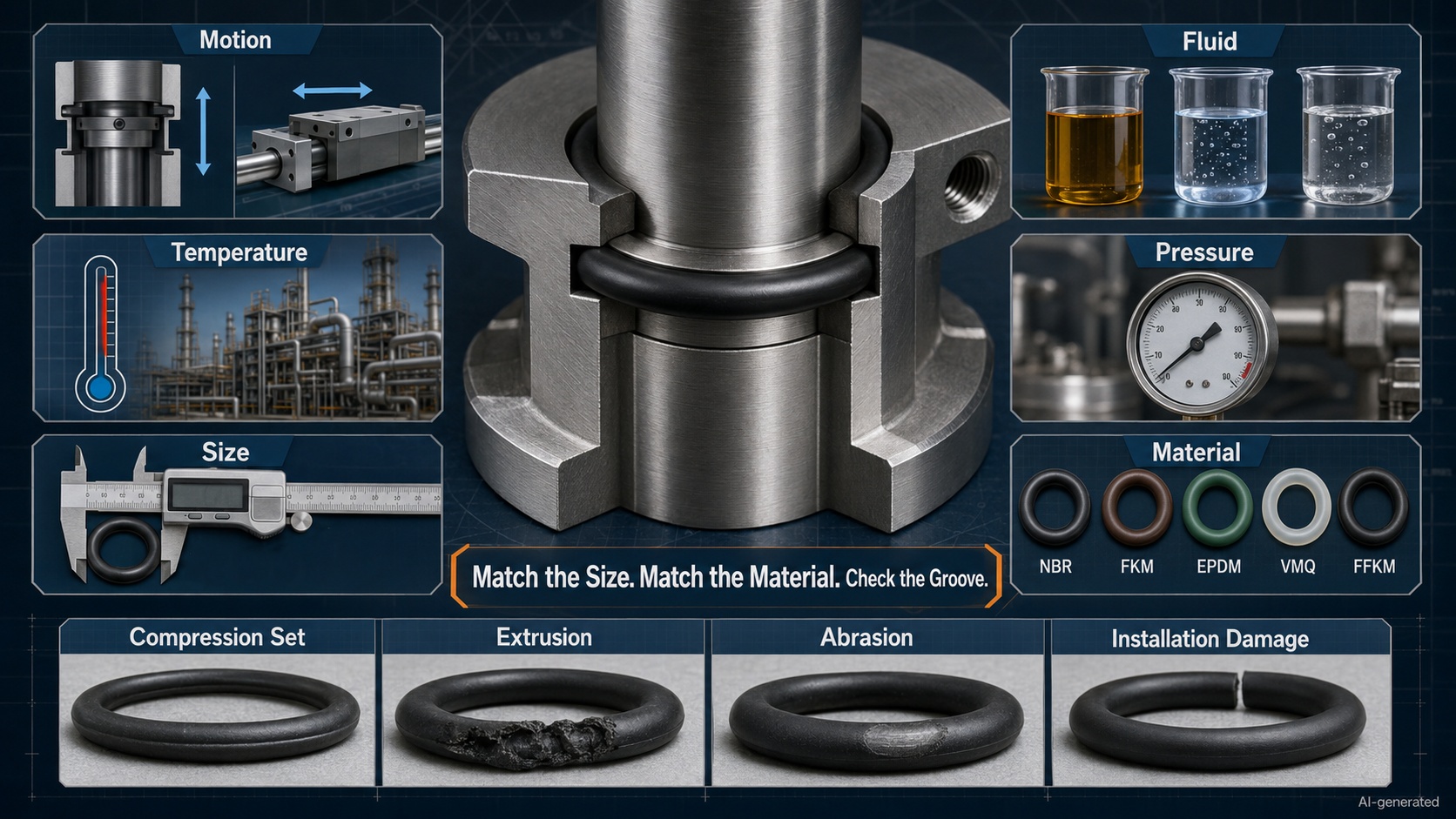
| Failure mode | Typical appearance | Common causes | Corrective direction |
| Compression set | Ring remains flattened after removal | Excessive heat, prolonged compression or unsuitable compound | Review material, squeeze and operating temperature |
| Extrusion | Edges appear bitten or torn | High pressure, excessive clearance or insufficient support | Reduce clearance or add appropriate backup support |
| Abrasion | Flat, polished or worn surface | Rough surfaces, poor lubrication or excessive movement | Improve surface finish, alignment or lubrication |
| Spiral failure | Twisted or diagonal surface damage | Rolling during reciprocating movement | Reduce friction and prevent twisting during installation |
| Swelling | Ring becomes soft or oversized | Chemical incompatibility | Select a compatible compound |
| Hardening | Brittle surface with visible cracks | Heat, ozone, oxidation or chemical attack | Review temperature and environmental resistance |
| Installation damage | Cuts or slices around the seal | Burrs, tools, sharp edges or exposed threads | Improve lead-in geometry and installation protection |
| Rapid gas decompression | Internal blistering or rupture | Absorbed gas expands during rapid pressure reduction | Use a resistant compound and control decompression |
When a seal fails, replacing it with an identical part may restore operation without correcting the underlying cause. The groove, mating surfaces, pressure conditions, movement and fluid exposure should also be inspected.
The O-Ring Failure Guide: Causes, Symptoms and Solutions provides a more detailed diagnostic process.
Frequently Asked Questions
What do O-Ring sizes mean?
An O-Ring size normally identifies its inside diameter and cross-section. Some standards use size codes or dash numbers that correspond to defined dimensions and tolerances.
How do I calculate O-Ring outside diameter?
Use the formula:
OD=ID+2(CS)
For a 20 mm ID and a 3 mm cross-section, the nominal outside diameter is 26 mm.
What is the most common O-Ring material?
NBR is widely used for general industrial sealing because it performs well with many mineral oils and lubricants and is relatively economical. It is not suitable for every fluid or operating environment.
What is the difference between NBR and FKM?
NBR is commonly selected for mineral oil, grease and general hydraulic or pneumatic applications. FKM generally provides better resistance to high temperatures, fuels and many chemicals. Compatibility still depends on the exact compound and medium.
Is a 70 Shore A O-Ring suitable for every application?
No. Around 70 Shore A is a common general-purpose hardness, but pressure, clearance, movement and sealing-surface condition may favor a softer or harder compound.
Can an O-Ring be used on a rotating shaft?
It can be used in selected slow-speed, well-lubricated rotary applications. Continuous high-speed rotation normally requires a dedicated rotary shaft seal.
Does O-Ring color identify its material?
Not reliably. Some manufacturers use color to distinguish compounds, but there is no universal color code covering all O-Ring materials.
Can an O-Ring be reused?
Reusing a seal is generally not recommended in critical assemblies. An apparently intact ring may have compression set, chemical damage or small surface cuts that are difficult to see.
Why does a new O-Ring still leak?
Possible causes include incorrect size, insufficient squeeze, an oversized groove, surface damage, twisting, contamination, incompatible material or excessive clearance.
Is a thicker O-Ring always better?
No. A thicker cross-section changes squeeze, groove fill and assembly force. The selected size must match the groove rather than simply provide more elastomer.
Conclusion
Reliable O-Ring performance depends on the complete sealing system: size, material, hardness, groove geometry, pressure, temperature, movement, fluid compatibility and installation quality.
Begin by defining the application. Then select a compatible material, verify the size and groove, choose an appropriate hardness and test the assembly under realistic operating conditions.
This approach applies equally to a simple water fitting, a pneumatic cylinder, a sensor enclosure and a precision mechatronic module.
The O-Ring may be one of the least visually impressive parts in a machine, but when it fails, it has an impressive talent for becoming everyone’s problem. Careful selection keeps it where it belongs—out of sight and doing its job.
Keep Learning
O-Ring Applications in Mechatronic Systems: Design and Selection Guide
An O-Ring in a mechatronic system does more than stop fluid from escaping. It may preserve pneumatic pressure, maintain vacuum holding force, protect a sensor from coolant, contain liquid around power electronics or keep a dispensing process repeatable. This matters because mechatronic equipment connects mechanical movement with electronics, sensors and automated control. A small sealing problem can therefore become a motion problem, a measurement problem or even a system shutdown. A leaking pneumatic......
O-Ring Material Guide: NBR, FKM, EPDM, Silicone and FFKM
Choosing an O-Ring material is not simply a choice between "rubber" and "better rubber." The seal must remain flexible, chemically stable and mechanically supported throughout the actual operating cycle. A material that performs well in mineral oil may fail in steam. Another may tolerate high temperature but become too stiff during a cold startup. Even within the same polymer family, different compounds can deliver different hardness, compression set, cleanliness and service life. This guide compares ......
O-Ring Guide: Types, Materials, Sizes and Applications
An O-Ring is a circular sealing element with a round cross-section. Installed in a properly designed groove, it is compressed between two mating surfaces to prevent liquid or gas from passing through the joint. The design could hardly be simpler, yet the O-Ring is used in everything from household fittings and automotive systems to pneumatic cylinders, vacuum equipment, industrial robots and semiconductor machinery. That small ring quietly prevents leaks, protects components and keeps pressure where i......
O-Ring Size Guide: How to Measure and Choose the Right Size
An O-Ring can have the correct material, suitable hardness and excellent chemical resistance—and still leak because its dimensions are wrong. Selecting the right O-Ring size begins with three measurements: inside diameter, cross-section and outside diameter. The arithmetic is simple. The engineering decision is not. Manufacturing tolerances, groove geometry, installation stretch, operating pressure and the condition of the old seal can all change which size is actually suitable. This O-Ring size guide......
How to Install an O-Ring Without Damaging It
Installing an O-Ring looks simple: place the ring in the groove, assemble the components and move on. In practice, many O-Ring failures begin during those few seemingly harmless seconds. A burr can cut the sealing surface. An incompatible lubricant can soften or swell the material. Excessive stretching can reduce the cross-section, while rolling the ring into the groove can create a twist that later develops into spiral failure. The frustrating part is that installation damage is not always immediatel......
O-Ring Failure Guide: Causes, Symptoms and Solutions
An O-Ring rarely fails without leaving clues. A flattened cross-section may suggest compression set. Ragged edges can point to extrusion. A soft, swollen seal often indicates chemical incompatibility, while fine surface cracks may reveal heat, ozone or environmental attack. The difficulty is that several problems can produce similar symptoms—and several causes can act together. For example, an incompatible fluid may soften an O-Ring. The softened material then becomes easier to extrude through a clear......