O-Ring Size Guide: How to Measure and Choose the Right Size
20 min
- Key Takeaways
- 1. What Do O-Ring Sizes Mean?
- 2. How to Measure an O-Ring
- 3. How to Measure Small or Soft O-Rings
- 4. Why a Used O-Ring May Give the Wrong Size
- 5. How to Read an O-Ring Size Chart
- 6. AS568 O-Ring Sizes Explained
- 7. ISO 3601 and Metric O-Ring Sizes
- 8. How to Choose an O-Ring Size for a Groove
- 9. How Stretch, Squeeze and Tolerance Change the Installed Size
- 10. Worked O-Ring Size Examples
- 11. Common O-Ring Sizing Mistakes
- 12. O-Ring Size Selection Workflow
- Frequently Asked Questions
- Conclusion
An O-Ring can have the correct material, suitable hardness and excellent chemical resistance—and still leak because its dimensions are wrong.
Selecting the right O-Ring size begins with three measurements: inside diameter, cross-section and outside diameter. The arithmetic is simple. The engineering decision is not. Manufacturing tolerances, groove geometry, installation stretch, operating pressure and the condition of the old seal can all change which size is actually suitable.
This O-Ring size guide explains how to measure an O-Ring, calculate missing dimensions, read AS568 and metric size information, evaluate tolerances and choose a size that fits the groove rather than merely looking close enough.
For a broader introduction to seal types, materials and applications, start with the O-Ring Guide: Types, Materials, Sizes and Applications.
Key Takeaways
· An O-Ring size is normally defined by its inside diameter and cross-section.
· Outside diameter is calculated as OD = ID + 2 × CS.
· Measure an unused O-Ring without stretching or compressing it.
· A used seal may be swollen, flattened, worn or permanently stretched, so it is not always a reliable sizing reference.
· AS568 dash numbers identify dimensions and tolerances; they do not identify material or hardness.
· Metric, ISO, national and supplier series are not automatically interchangeable.
· Nominal dimensions are not the same as the permitted minimum and maximum dimensions.· The final size must work with the groove, sealing motion, pressure, clearance and installation conditions.
1. What Do O-Ring Sizes Mean?
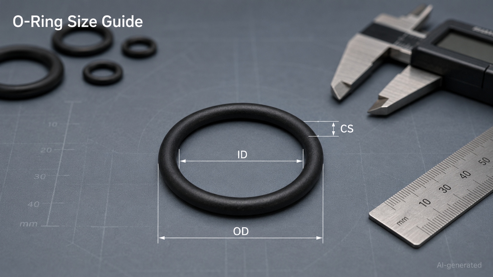
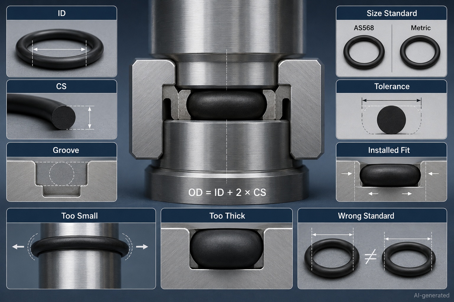
A conventional O-Ring has a circular shape and a round cross-section. Its size is described by three basic dimensions:
· Inside Diameter (ID): the diameter of the opening through the center
· Cross-Section (CS): the thickness of the circular cord
· Outside Diameter (OD): the overall diameter measured from one outside edge to the opposite outside edge
The relationship between them is:
OD = ID + 2(CS)
If the inside and outside diameters are known, the cross-section can be calculated:

If the outside diameter and cross-section are known, the inside diameter can be calculated:
ID = OD - 2(CS)
Basic O-Ring Dimension Example
Suppose an O-Ring has:
· ID: 20 mm
· CS: 3 mm
Its nominal OD is:
20 + 2(3) = 26 mm
This relationship is useful for checking a measurement, but it does not establish the dimensional tolerance or confirm that the ring fits a particular groove.
Why O-Ring Size Is Usually Written as ID × CS
Metric O-Ring dimensions are commonly expressed as:
Inside Diameter × Cross-Section
For example:
20 mm × 3 mm
This means a nominal 20 mm inside diameter and 3 mm cross-section—not a 20 mm outside diameter.
That distinction sounds obvious until a replacement arrives looking suspiciously like a rubber bracelet. Always confirm which dimension comes first in the supplier’s drawing or size table.
2. How to Measure an O-Ring
The best sizing reference is a clean, unused O-Ring together with the original drawing or product specification. When those are unavailable, careful physical measurement can help identify the likely size.
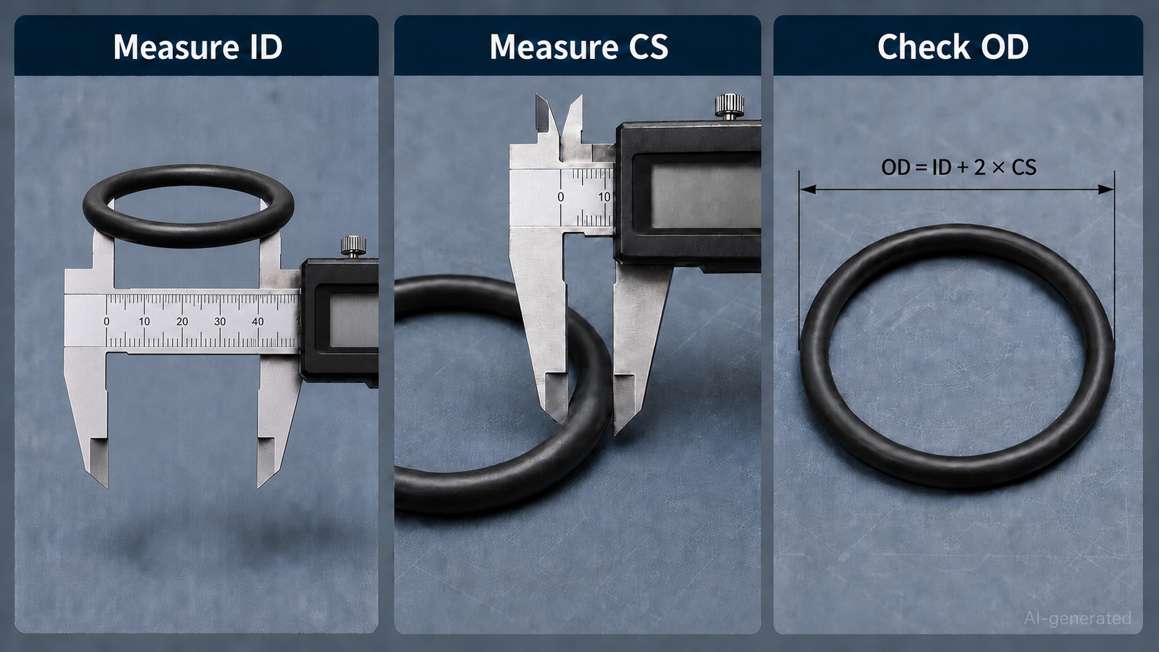
Tools for Measuring an O-Ring
Depending on size and required accuracy, useful tools include:
· Digital or vernier caliper
· O-Ring sizing cone
· Circumference or diameter tape
· Optical comparator
· Measuring microscope or vision system
· Dedicated cross-section gauge
A digital caliper is practical for many general industrial O-Rings. It is less reliable for miniature rings, very soft compounds or close-tolerance inspection because the jaws can deform the elastomer.
Step 1: Clean and Condition the O-Ring
Remove oil, dirt and loose contamination using a cleaning method compatible with the material. Allow the ring to return to room temperature and its relaxed shape.
Do not measure it immediately after stretching, heating or removing it from a pressurized assembly. Elastomers need time to recover, and some damage is permanent.
Step 2: Measure the Inside Diameter
Place the O-Ring on a clean, flat surface without stretching it.
For a medium or large ring:
1.Position the inside-measuring jaws of the caliper lightly against the inner wall.
2.Keep the jaws aligned with the widest part of the opening.
3.Apply only enough force to make contact.
4.Repeat the measurement after rotating the ring.
If the ring is too large for the caliper, measure its relaxed circumference and calculate the diameter:

where (C) is the inside circumference. The measurement method and tape thickness must be considered if high accuracy is required.
Step 3: Measure the Cross-Section
Close the external jaws gently around the cord. Do not squeeze the rubber into an oval.
Measure the cross-section at several locations around the ring. Variations may reveal:
· Compression set
· Wear
· Mold mismatch
· Flash
· Local damage
· Distortion from storage or service
For a new, round O-Ring, the readings should be reasonably consistent within the product’s tolerance. If the measured cross-section varies widely, the seal may no longer be a trustworthy size reference.
Step 4: Measure or Calculate the Outside Diameter
For small and medium rings, lightly measure across the outermost edges. Then check the result using:
OD = ID + 2(CS)
If the direct OD measurement and calculated OD differ significantly, recheck for jaw pressure, misalignment or a deformed ring.
Step 5: Compare the Measurements with a Size Table
Match the results against:
· The equipment drawing
· The original part number
· The applicable standard
· The supplier’s dimension table
· The actual groove dimensions
Do not round immediately to the nearest whole millimeter. A nominal 2.62 mm cross-section, for example, may belong to an inch-based standard family rather than a nominal 2.5 mm or 3 mm metric family.
3. How to Measure Small or Soft O-Rings
Miniature O-Rings and low-hardness compounds require extra care. A small measuring force that is harmless to a steel part may visibly compress a soft elastomer.
Common Measurement Problems
| Problem | Effect on the reading | Better approach |
| Excessive caliper force | Cross-section reads too small | Use light contact or a low-force optical method |
| Ring stretched during ID measurement | ID reads too large and CS becomes smaller | Measure in the relaxed state |
| Jaws not centered | ID or OD reads too small | Repeat after rotating and realigning the ring |
| Flash included in the reading | CS or OD reads too large | Measure away from the parting line |
| Out-of-round ring | Readings vary by orientation | Record multiple axes and inspect the groove or drawing |
| Warm component | Dimensions may temporarily change | Condition the seal at a controlled temperature |
For precision pumps, miniature valves, test sockets and compact fluid connectors, a vision system or measuring microscope may provide more repeatable results than a handheld caliper.
The smaller the O-Ring, the larger a tiny error becomes as a percentage of the total dimension. A 0.10 mm error on a large static cover seal may be manageable; on a miniature fluid passage, it may be the entire tolerance budget.
More detailed considerations for miniature seals are covered in the Small O-Ring Guide for Precision Equipment..
4. Why a Used O-Ring May Give the Wrong Size
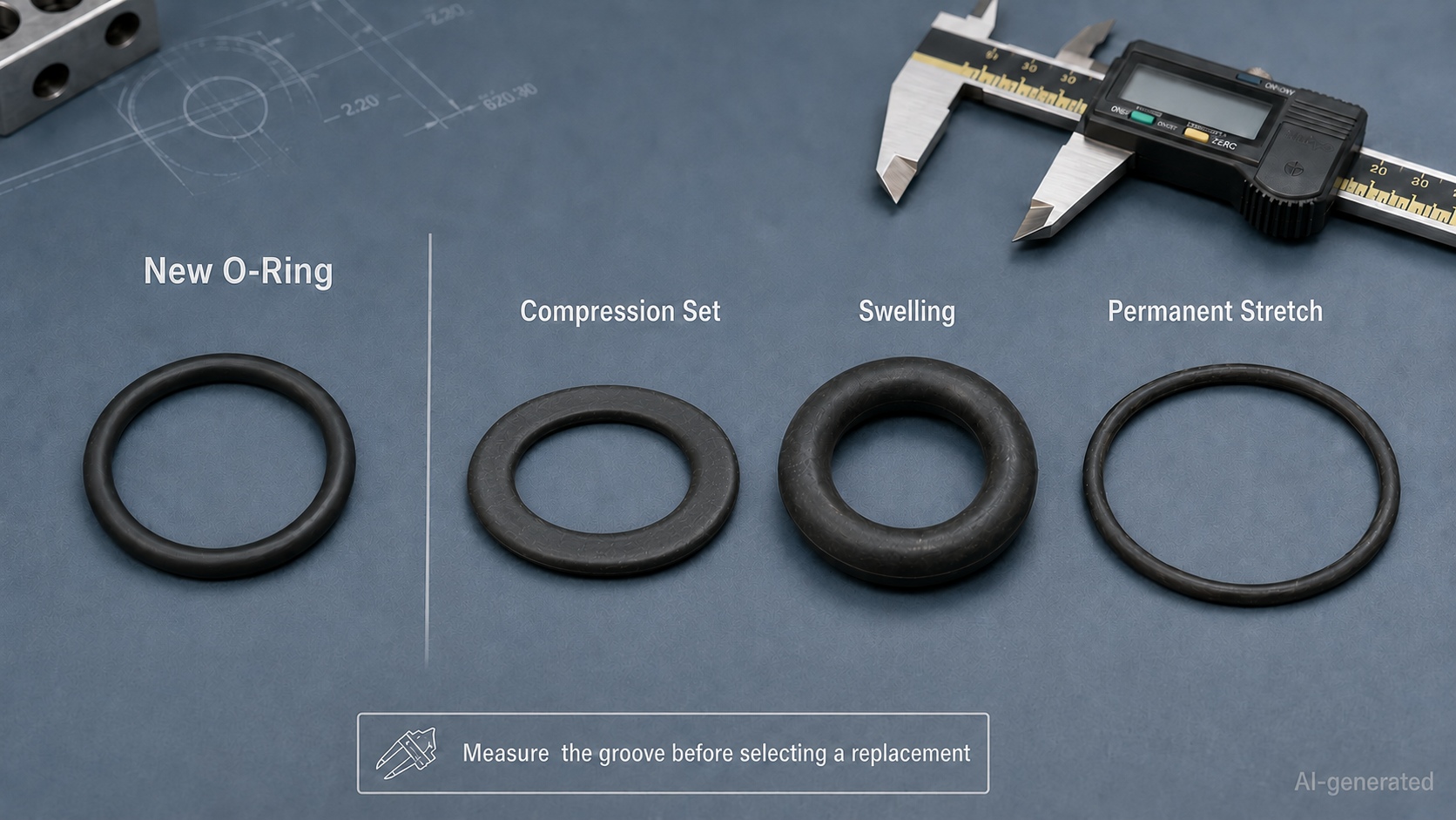
A used O-Ring is evidence, but it is not necessarily a blueprint.
During service, an elastomer may experience:
· Compression set
· Chemical swelling
· Material shrinkage
· Thermal aging
· Abrasion
· Extrusion
· Permanent stretch
· Flattening at the sealing surfaces
An O-Ring that originally had a round 3 mm cross-section may measure smaller in one direction after long-term compression. A chemically swollen seal may measure larger than its original nominal size. A piston seal may remain stretched after removal.
What to Measure When the Old Seal Is Deformed
Use as many independent references as possible:
1.Check the equipment manual or drawing.
2.Search the original manufacturer’s part number.
3.Measure the groove diameter, depth and width.
4.Inspect the bore, rod, piston or face-seal geometry.
5.Identify whether the joint is static, reciprocating, rotary or vacuum.
6.Compare the old seal with standard size families.
7.Determine whether chemical exposure changed the material.
If the seal failed, replacing it solely by matching its current dimensions can reproduce the wrong condition. The O-Ring Failure Guide: Causes, Symptoms and Solutions can help distinguish size-related leakage from material, pressure or installation problems.
5. How to Read an O-Ring Size Chart
An O-Ring size chart normally includes some combination of:
· Size code or dash number
· Nominal ID
· ID tolerance
· Nominal CS
· CS tolerance
· Nominal OD
· Inch and metric conversions
Nominal Size vs Actual Permitted Size
A nominal dimension is the reference size used for identification. The manufactured part is allowed to vary within a specified tolerance.
For example, a chart may list:
CS = 1.78 ± 0.08 mm
The acceptable cross-section range would be:
1.70 mm to 1.86 mm
This does not mean any O-Ring measuring 1.70 to 1.86 mm is interchangeable. The ID, material, inspection method, groove and application must also match.
Inch Values and Metric Conversions
An inch-standard size may be displayed in millimeters for convenience. The converted value does not turn it into a native metric size.
For example:
0.103 in x 25.4 = 2.6162mm
This is normally shown as approximately 2.62 mm. It should not automatically be replaced with a 2.5 mm or 2.6 mm metric O-Ring.
Do Not Compare Size Codes Alone
A code such as “P20,” “G25,” “AS-214” or “-214” only makes sense within its defined standard or supplier series. Identical-looking numbers can represent different dimensions in different systems.
When purchasing a replacement, compare the actual ID, CS and tolerances—not just the code printed on a bag.
6. AS568 O-Ring Sizes Explained
SAE AS568F specifies O-Ring inside diameters, cross-sections, tolerances and dash-number identification codes for sealing applications and straight-thread tube-fitting boss gaskets. The current AS568F edition was reaffirmed in January 2026.
An AS568 dash number identifies a dimensional size. It does not specify:
· Elastomer family
· Compound formulation
· Hardness
· Color
· Chemical compatibility
· Temperature capability
Two products with the same AS568 dash number can therefore have the same nominal dimensions but very different performance.
Common AS568 Cross-Section Families
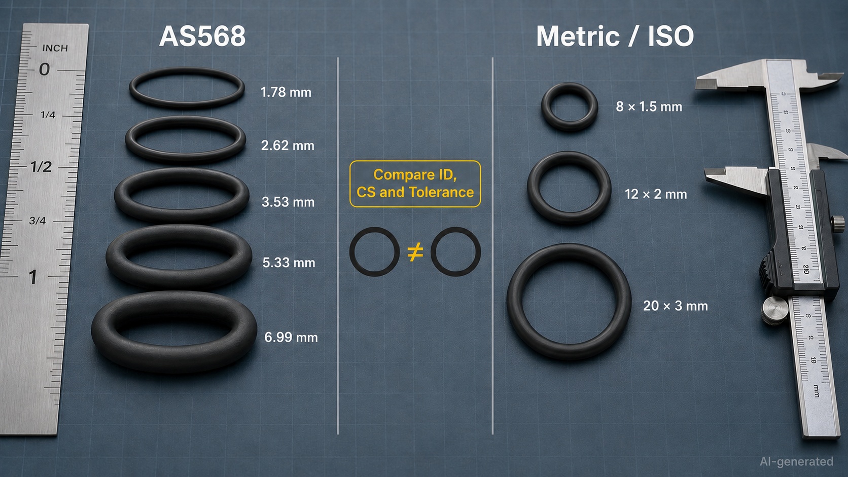
AS568 sizes are organized around five widely used nominal cross-section families. Parker’s published AS568 dimensional data shows the following nominal values:
| Common dash-number family | Nominal CS, inch | Approximate CS, mm |
| 0xx family | 0.070 | 1.78 |
| 1xx family | 0.103 | 2.62 |
| 2xx family | 0.139 | 3.53 |
| 3xx family | 0.210 | 5.33 |
| 4xx family | 0.275 | 6.99 |
Some small dash numbers have special dimensions, so the family summary must not replace the official chart. Use the complete standard or a manufacturer’s current dimensional table for the exact ID and tolerance of a specific dash number.
How to Use an AS568 Dash Number
If the required size is listed as AS568-214, confirm:
1.The full dash number
2.Nominal ID
3.Nominal CS
4.ID and CS tolerances
5.Material and compound
6.Hardness
7.Application and groove
Writing only “214 O-Ring” on a purchase request leaves unnecessary room for interpretation. Include the standard designation and material specification.
7. ISO 3601 and Metric O-Ring Sizes
ISO 3601-1 specifies O-Ring inside diameters, cross-sections, tolerances and designation codes for general industrial and aerospace fluid-power applications. ISO states that the 2012 edition was reviewed and confirmed in 2022, so it remains current; it also has a 2019 amendment.
ISO 3601-1 is a dimensional standard. It should not be confused with ISO 3601-2, which addresses housing or gland dimensions for specified O-Ring classes and selected hydraulic and pneumatic arrangements.
In practical terms:
· ISO 3601-1 helps define the O-Ring
· ISO 3601-2 helps define the space that holds it
Both matter, but they answer different questions.
Metric Does Not Always Mean ISO 3601
An O-Ring listed in millimeters may follow:
· ISO 3601
· A national standard
· A regional industrial series
· An equipment manufacturer’s specification
· A supplier-specific catalog system
Therefore, “20 × 3 mm” is useful dimensional information but not a complete standard designation.
JLCMC O-Ring Series
The JLCMC O-Ring category includes National Standard, P, S, G, V and AS catalog series, along with small-inner-diameter products. These labels help organize the selection, but the individual product drawing and dimension table remain the final reference.
Do not assume:
· “AS Series” automatically means an AS568 dash number
· “P Series” and “G Series” with similar codes have the same dimensions
· Two rings with close IDs have the same cross-section
· A catalog series defines material or hardness by itself
Confirm the series, size code, ID, CS, tolerance, material, hardness and intended sealing state before ordering.
8. How to Choose an O-Ring Size for a Groove
For a new design, the groove and O-Ring should be selected as a system. For a replacement, the groove provides an important independent check on the old seal.
Static Radial Seal
A static radial seal is compressed between cylindrical surfaces, such as a plug in a bore or a tube inside a housing.
Check:
· Bore diameter
· Rod, plug or piston diameter
· Groove diameter
· Groove depth
· Groove width
· Diametral clearance
· Pressure direction
The selected ID must place the O-Ring correctly on the male or female component, while the CS and groove depth create suitable compression.
Static Face Seal
A face seal sits in a groove on a flat surface and is compressed axially by a cover or flange.
Check:
· Groove inside and outside diameters
· Groove depth
· Groove width
· Pressure direction
· Bolt spacing
· Housing stiffness
Pressure direction influences whether the ring should locate toward the inner or outer groove wall. The cover must also remain stiff enough to maintain compression between fasteners.
Reciprocating Seal
A reciprocating O-Ring seals a moving piston or rod. Size selection must account for:
· Dynamic squeeze
· Friction
· Lubrication
· Surface finish
· Side loading
· Wear
· Pressure cycling
A thicker or more tightly squeezed O-Ring is not automatically better. Excessive compression can increase breakaway force, heat and wear.
Rotary Seal
Standard O-Rings are generally limited to selected slow-speed, well-lubricated rotary duties. Installation stretch, frictional heat and shaft finish are particularly important. High-speed continuous rotation normally requires a dedicated rotary seal.
Vacuum Seal
Vacuum leakage can be sensitive to surface scratches, contamination, joint stiffness and material permeability. The size still matters, but a dimensionally correct ring cannot rescue a damaged sealing surface.
Detailed groove calculations belong in the O-Ring Groove Design Guide: Squeeze, Stretch and Gland Fill.
9. How Stretch, Squeeze and Tolerance Change the Installed Size
An O-Ring is selected in its free, uninstalled condition, but it performs in a deformed condition.
ID Stretch
When an O-Ring is installed over a piston, plug or shaft, its inside diameter may stretch. Stretch can reduce the effective cross-section due to elastomer deformation
ID stretch can be estimated as:
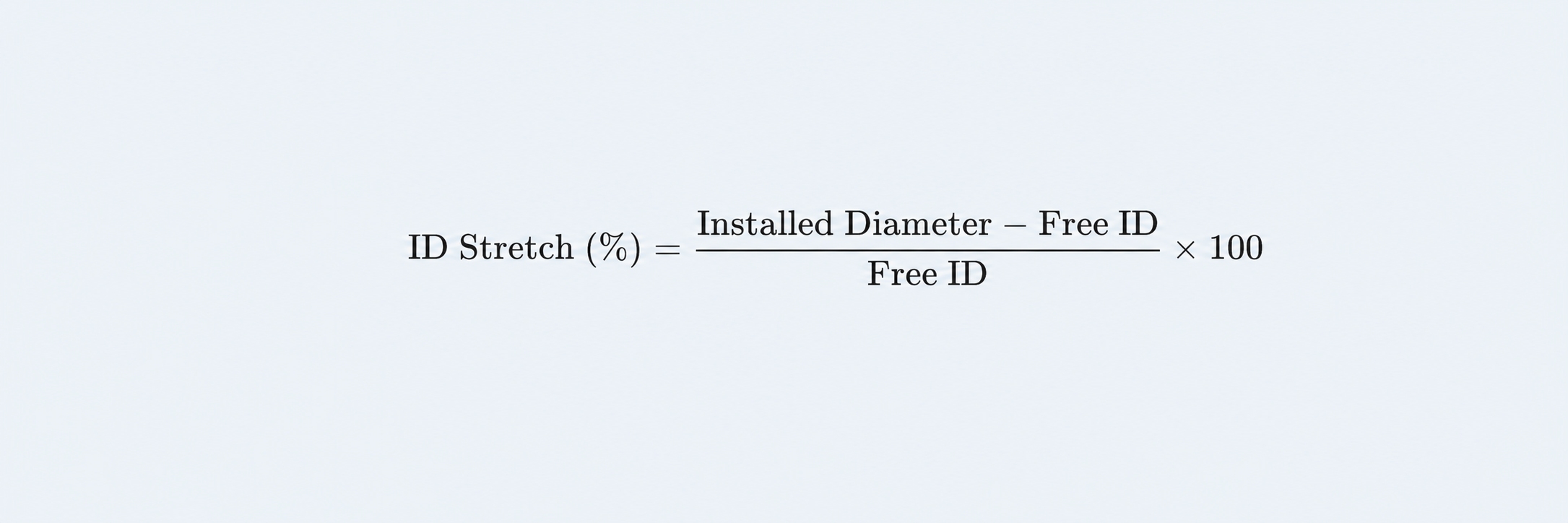
For example, if a ring with a 20.0 mm free ID is installed over a 20.6 mm diameter:

That does not automatically confirm the design. The permitted stretch depends on seal type, material, cross-section, operating conditions and the applicable design guidance.
Cross-Section Squeeze
Squeeze describes how much the cross-section is compressed after assembly:
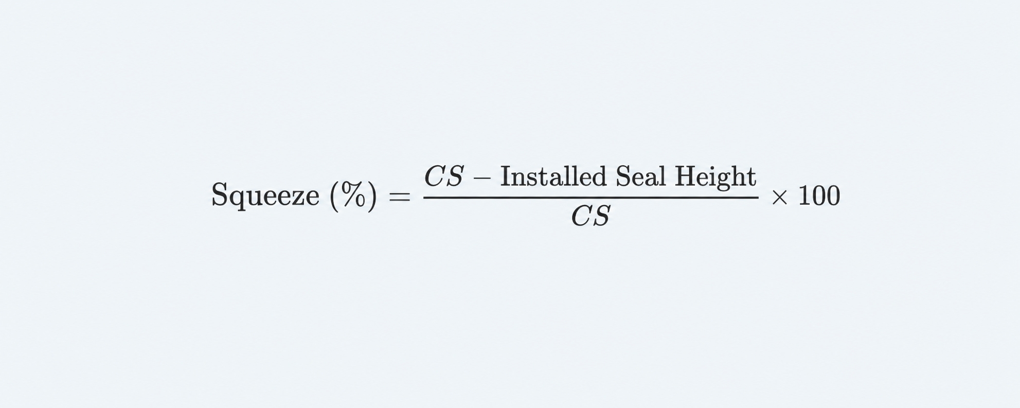
The suitable value differs for static face, static radial, reciprocating and rotary seals. Use the relevant standard or manufacturer’s gland table instead of applying one percentage to every design.
Gland Fill
The O-Ring must have room to deform and expand. Groove fill depends on the O-Ring volume and available groove volume.
A groove designed around the nominal part only may become overfilled when the O-Ring is at its maximum tolerance and the groove is at its minimum tolerance. Fluid swelling and thermal expansion can reduce the remaining space further.
Tolerance Stack-Up
For a robust design, evaluate at least:
· Maximum O-Ring CS
· Minimum O-Ring CS
· Minimum groove depth
· Maximum groove depth
· Minimum groove width
· Maximum and minimum hardware diameters
· Eccentricity or misalignment
· Clearance under pressure
The nominal combination may look perfect while the worst-case combination leaks or creates excessive friction. Tolerances are not small-print decoration; they are where many real assemblies live.
10. Worked O-Ring Size Examples
Example 1: Calculate OD from ID and CS
Given:
· ID = 12 mm
· CS = 2 mm
OD = 12 + 2(2) = 16 mm
The nominal O-Ring size is 12 × 2 mm, and its nominal outside diameter is 16 mm.
Example 2: Calculate CS from ID and OD
Measured:
· ID = 19.4 mm
· OD = 24.6 mm
A 2.6 mm reading may point toward a nominal 2.62 mm inch-standard cross-section, but this is only a clue. Check the ID, tolerances, original standard and whether the seal is used or deformed.
Example 3: Check a Metric Description
A catalog lists an O-Ring as:
8 × 1.5 mm
Assuming the catalog uses ID × CS:
OD = 8 + 2(1.5) = 11 mm
Before ordering, verify that 8 mm is indeed the ID, review the tolerance and confirm the material and groove.
Example 4: Replacement Ring Is Flattened
An old ring measures:
· ID approximately 30.5 mm
· CS between 2.4 and 2.9 mm, depending on orientation
Do not average the CS readings and order a 2.65 mm ring immediately.
Instead:
1.Inspect for compression set.
2.Measure the groove.
3.Check the shaft, bore or face-seal diameter.
4.Compare likely standard sizes.
5.Confirm whether swelling or wear occurred.
6.Review the original part number if available.
The variation suggests that service deformation is affecting the measurement.
11. Common O-Ring Sizing Mistakes
Measuring Only the Outside Diameter
Different ID and CS combinations can produce similar outside diameters. OD alone is rarely enough to identify the correct size.
Confusing Radius with Diameter
A drawing dimension taken from the centerline to the edge is a radius. The corresponding diameter is twice that value.
Treating Inch Conversions as Native Metric Sizes
An inch-standard 2.62 mm cross-section is not automatically interchangeable with a 2.5 mm metric cross-section.
Ignoring Tolerance
Nominal size does not describe the full permitted range. Groove performance must be checked at tolerance extremes.
Copying the Size of a Failed Seal
The old ring may be swollen, worn, stretched or incorrectly selected in the first place.
Choosing by Color
Color does not define dimensions, material or standard. It is a supplier convention at most, not a universal sizing code.
Assuming a Larger Cross-Section Seals Better
A larger CS may overfill the groove, increase assembly force and raise friction. The correct ring matches the groove; the biggest ring wins no prizes.
Ignoring Installation Stretch
Stretching a ring over a component changes both its ID and effective cross-section.
Mixing Size and Material Decisions
Size, material and hardness are separate specifications. After choosing the dimensions, verify fluid compatibility, temperature capability and hardness using the O-Ring Material Guide: NBR, FKM, EPDM, Silicone and FFKM.
12. O-Ring Size Selection Workflow
Use the following process for a new design or replacement.
Step 1: Define the Sealing Arrangement
Identify whether the joint is:
· Static radial
· Static face
· Reciprocating
· Rotary
· Oscillating
· Vacuum
Step 2: Identify the Size System
Determine whether the product follows:
· AS568
·ISO 3601
· Another national or regional standard
· An equipment-specific specification
· A supplier catalog series
Step 3: Record the Free O-Ring Dimensions
Confirm:
· ID
· CS
· OD
· Dimensional tolerances
Step 4: Measure the Hardware
Record the groove, bore, rod, piston, plug or face-seal dimensions. Include clearance and tolerance, not just nominal values.
Step 5: Calculate Installed Conditions
Evaluate:
· ID stretch
· Cross-section squeeze
· Groove fill
· Pressure clearance
· Worst-case tolerance stack
Step 6: Confirm Material and Hardness
The correct dimensions do not compensate for chemical incompatibility, excessive heat or unsuitable hardness.
Step 7: Check Installation
Confirm that the O-Ring can pass over threads, shoulders and ports without being cut or overstretched. Use protective sleeves, compatible lubricant and controlled assembly where required.
See How to Install an O-Ring Without Damaging It for the complete installation process.
Step 8: Test Under Real Conditions
Validate the selected size under realistic:
· Pressure
· Temperature
· Movement
· Fluid exposure
· Vibration
· Assembly tolerance
· Service duration
Quick O-Ring Size Checklist
Before ordering, confirm:
· Is the size written as ID × CS?
· Have ID, CS and OD been checked?
· Is the standard or catalog series identified?
· Are dimensional tolerances available?
· Was the old seal inspected for deformation?
· Do the groove dimensions match the intended seal?
· Have stretch, squeeze and gland fill been evaluated?
· Is the application static, dynamic or vacuum?
· Are material and hardness specified separately?
· Has installation access been considered?
Frequently Asked Questions
What are the three dimensions of an O-Ring?
The three basic dimensions are inside diameter, cross-section and outside diameter. Size is normally specified by ID and CS, while OD can be calculated.
How do I calculate O-Ring outside diameter?
Use:
OD = ID + 2(CS)
An O-Ring with a 10 mm ID and 2 mm CS has a nominal 14 mm OD.
How do I calculate O-Ring cross-section?
If ID and OD are known:
CS = ( OD - ID ) / 2
Can I measure an O-Ring with a caliper?
Yes, a caliper is suitable for many general-purpose O-Rings. Use light contact and take several readings. Miniature, very soft or close-tolerance rings may require optical or specialist measuring equipment.
Should I measure an O-Ring stretched or relaxed?
Measure it relaxed. Stretching increases the ID and reduces the effective cross-section, producing misleading readings.
Can I identify an O-Ring from its outside diameter alone?
Usually not. Different ID and CS combinations can have similar outside diameters. Measure at least ID and CS and identify the applicable standard or series.
What does an AS568 dash number mean?
It identifies a defined dimensional size and tolerance under SAE AS568. It does not specify material, compound, hardness or color.
Are AS568 O-Rings metric?
AS568 is an inch-based size system, although charts often provide metric conversions. A converted millimeter value should not be confused with a native metric size.
Are ISO 3601 and AS568 sizes interchangeable?
Not automatically. Some dimensions may be close, but the size codes, nominal dimensions and tolerances must be compared individually.
Why does a correctly measured O-Ring still leak?
Possible causes include an incorrect groove, insufficient squeeze, excessive clearance, damaged surfaces, twisting, contamination, material incompatibility or pressure-related extrusion.
Can I replace an O-Ring with a thicker one?
Only if the groove and application are designed for it. A thicker ring can overfill the groove, increase friction and make assembly difficult.
What size O-Ring should I use for a 20 mm shaft?
Shaft diameter alone is insufficient. The answer depends on whether the seal is static or dynamic, the groove diameter and depth, required stretch, cross-section, pressure, clearance and tolerance.
Conclusion
Choosing an O-Ring size is more than finding a ring with a familiar diameter. Start with ID and CS, calculate the OD, identify the relevant size system and check the dimensional tolerances. Then verify how the ring behaves inside the actual groove.
For replacement work, treat a used O-Ring carefully: its present shape may reflect years of pressure, heat, motion or chemical exposure rather than its original size. When possible, confirm the equipment drawing, part number and groove dimensions.
For new designs, select the O-Ring and gland together. Stretch, squeeze, groove fill and clearance determine whether the nominal dimensions become a reliable seal or merely a neatly packaged future leak.
Once the application and dimensions are defined, engineers can compare suitable products in the JLCMC O-Ring selection by series, material, hardness and intended use.
Keep Learning
O-Ring Applications in Mechatronic Systems: Design and Selection Guide
An O-Ring in a mechatronic system does more than stop fluid from escaping. It may preserve pneumatic pressure, maintain vacuum holding force, protect a sensor from coolant, contain liquid around power electronics or keep a dispensing process repeatable. This matters because mechatronic equipment connects mechanical movement with electronics, sensors and automated control. A small sealing problem can therefore become a motion problem, a measurement problem or even a system shutdown. A leaking pneumatic......
O-Ring Material Guide: NBR, FKM, EPDM, Silicone and FFKM
Choosing an O-Ring material is not simply a choice between "rubber" and "better rubber." The seal must remain flexible, chemically stable and mechanically supported throughout the actual operating cycle. A material that performs well in mineral oil may fail in steam. Another may tolerate high temperature but become too stiff during a cold startup. Even within the same polymer family, different compounds can deliver different hardness, compression set, cleanliness and service life. This guide compares ......
O-Ring Guide: Types, Materials, Sizes and Applications
An O-Ring is a circular sealing element with a round cross-section. Installed in a properly designed groove, it is compressed between two mating surfaces to prevent liquid or gas from passing through the joint. The design could hardly be simpler, yet the O-Ring is used in everything from household fittings and automotive systems to pneumatic cylinders, vacuum equipment, industrial robots and semiconductor machinery. That small ring quietly prevents leaks, protects components and keeps pressure where i......
O-Ring Size Guide: How to Measure and Choose the Right Size
An O-Ring can have the correct material, suitable hardness and excellent chemical resistance—and still leak because its dimensions are wrong. Selecting the right O-Ring size begins with three measurements: inside diameter, cross-section and outside diameter. The arithmetic is simple. The engineering decision is not. Manufacturing tolerances, groove geometry, installation stretch, operating pressure and the condition of the old seal can all change which size is actually suitable. This O-Ring size guide......
How to Install an O-Ring Without Damaging It
Installing an O-Ring looks simple: place the ring in the groove, assemble the components and move on. In practice, many O-Ring failures begin during those few seemingly harmless seconds. A burr can cut the sealing surface. An incompatible lubricant can soften or swell the material. Excessive stretching can reduce the cross-section, while rolling the ring into the groove can create a twist that later develops into spiral failure. The frustrating part is that installation damage is not always immediatel......
O-Ring Failure Guide: Causes, Symptoms and Solutions
An O-Ring rarely fails without leaving clues. A flattened cross-section may suggest compression set. Ragged edges can point to extrusion. A soft, swollen seal often indicates chemical incompatibility, while fine surface cracks may reveal heat, ozone or environmental attack. The difficulty is that several problems can produce similar symptoms—and several causes can act together. For example, an incompatible fluid may soften an O-Ring. The softened material then becomes easier to extrude through a clear......