What Role Does a Stepper Motor Play In a 3D Printer?
7 min
- What Is a Stepper Motor?
- The Role of Stepper Motors in a 3D Printer
- Operating Principle: Why Motion Occurs in Steps
- Advantages and Limitations of Stepper Motors in 3D Printers
- Key Factors Affecting Print Quality
- Precision Motion, Perfect Prints: JLCMC Stepper Motors for 3D Printing
- Frequently Asked Questions
- How to Use a Stepper Motor in a 3D Printer
- Conclusion
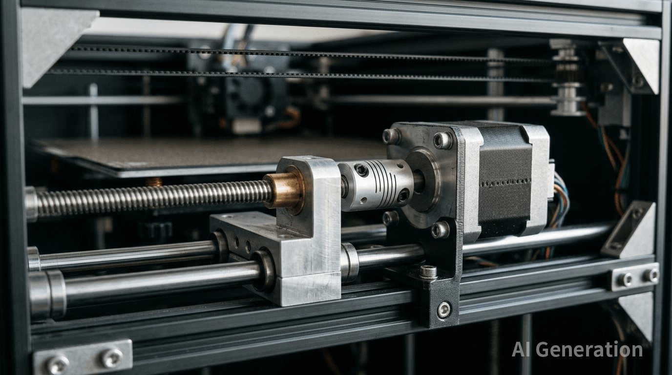
Most 3D printers, particularly those based on FDM (Fused Deposition Modeling), achieve motion through precisely controlled incremental steps. This stepwise motion behavior is not merely a byproduct of the process but a direct consequence of the underlying drive technology. At the core of these motion systems are stepper motors, which convert digital control signals into repeatable mechanical positioning.
What Is a Stepper Motor?
A stepper motor is, fundamentally, an actuator that converts electrical pulses into angular displacement. A conventional DC motor rotates continuously when powered, with speed proportional to the applied voltage. A stepper motor behaves differently: each pulse sent by the controller produces a fixed angular movement, typically 1.8°. In practical terms, 200 pulses complete exactly one revolution, enabling precise position control without the need for an external encoder to provide feedback.
This characteristic makes stepper motors inherently suitable for applications requiring accurate positioning. In 3D printing, layer heights are often 0.1 mm or even 0.05 mm. The nozzle position and build platform height must be controlled with high precision. A stepper motor functions like a calibrated indexing mechanism—each commanded step corresponds to a defined movement.
The Role of Stepper Motors in a 3D Printer
In a typical FDM 3D printer, four to five stepper motors are used:
- One motor for the X-axis and one for the Y-axis, controlling horizontal motion of the print head
- One or two motors for the Z-axis, responsible for the vertical positioning of the build platform
- One motor in the extruder, feeding filament into the hot end at a controlled rate
- Their primary function is not high speed, but precise motion control. X/Y motors influence edge definition within each layer, the Z motor determines layer consistency, and the extruder motor regulates material flow relative to motion. Poor coordination among these axes can result in layer misalignment, delamination, or under-extrusion.
- In practice, system tuning is critical. For example, periodic surface artifacts such as ripples can be traced to insufficient driver current, causing missed steps under load. Increasing the current to an appropriate level restores consistent motion, highlighting that motor performance depends on the entire electromechanical system rather than the motor alone.
Operating Principle: Why Motion Occurs in Steps
A stepper motor consists of a rotor and a stator. The rotor is typically a permanent magnet or toothed ferromagnetic structure, while the stator contains multiple electromagnetic coils. By energizing these coils in sequence, the controller generates a stepwise change in the magnetic field that incrementally pulls the rotor into alignment.
In a common two-phase bipolar hybrid stepper motor with four leads, energizing the coils in the sequence A+ → B+ → A− → B− produces clockwise rotation; reversing the sequence yields counterclockwise motion. Each change in excitation state advances the rotor by one full step position (in full-step mode).
A key limitation is that stepper motors typically operate without feedback (open-loop control). The controller assumes each pulse results in one step. However, if the load is too high, the current is too low, or the speed is too high, the motor may fail to keep up, resulting in “missed steps.” When this occurs, the system loses positional accuracy without detecting the error, which can accumulate over the remainder of the print.
Advantages and Limitations of Stepper Motors in 3D Printers
Advantages:
- Open-loop position control simplifies system design and reduces cost
- High torque at low speeds, suitable for steady, controlled motion
- Holding torque when stationary helps maintain position during pauses
- High repeatability, typically within ±0.05°
Limitations:
- Torque drops significantly at higher speeds, limiting maximum travel velocity
- Discrete stepping introduces vibration and audible noise, especially in full-step mode
- Continuous current leads to heat generation during operation
- No inherent feedback; missed steps cannot be detected in real time
Key Factors Affecting Print Quality
Driver Current Setting
Motor torque is directly related to current. Insufficient current increases the risk of missed steps, while excessive current causes overheating and potential driver protection triggers. A typical setting is 70%–100% of the rated current, followed by fine-tuning based on actual performance.
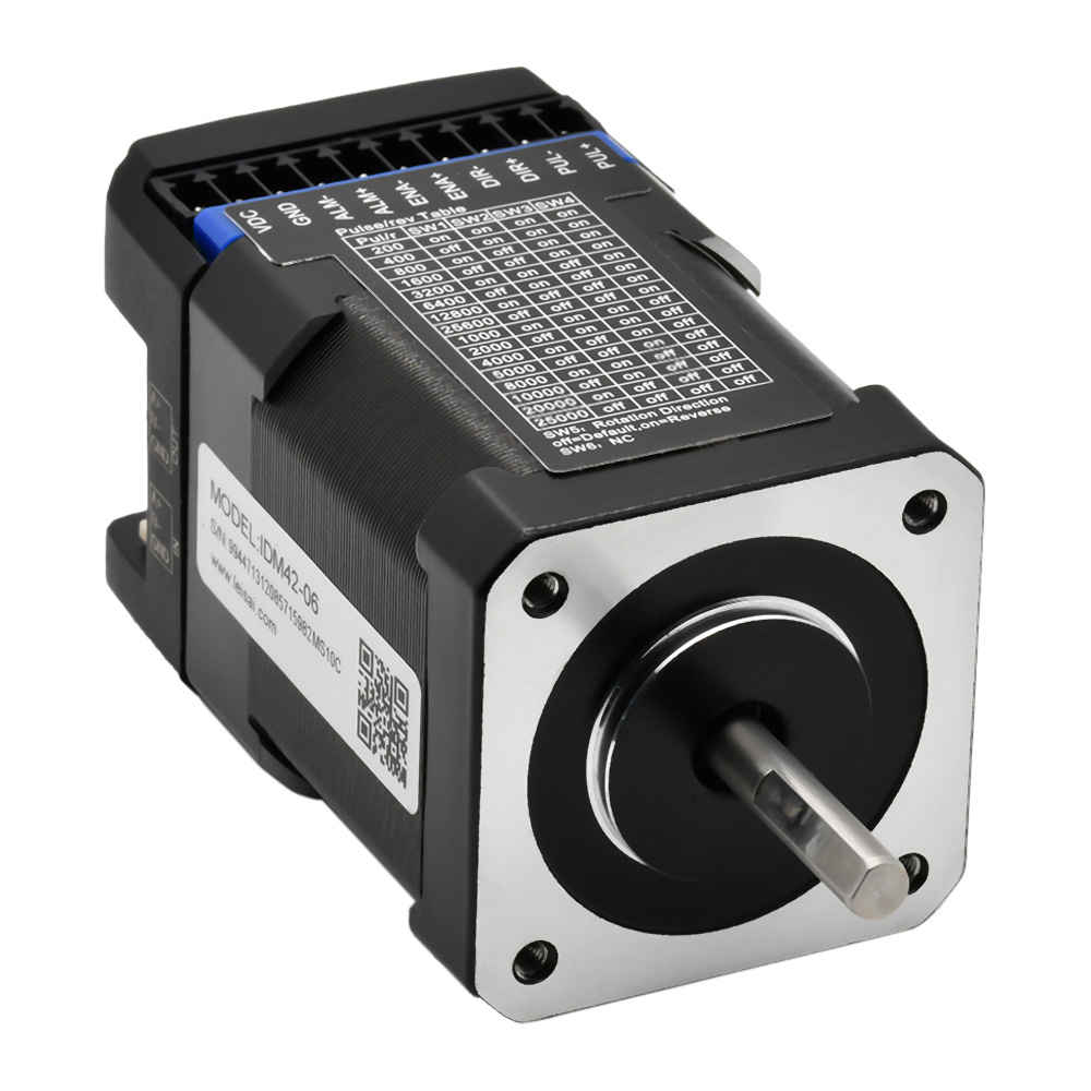
Microstepping Configuration
Microstepping subdivides a full step into smaller increments (e.g., 16× microstepping converts 200 steps per revolution into 3200). This improves motion smoothness and reduces vibration, but also reduces available torque and increases control signal requirements. In most 3D printing applications, 16× or 32× microstepping provides a practical balance.
Mechanical Design
Mechanical components significantly influence final accuracy. Lead screw pitch, belt tension, and bearing or guide clearances all contribute to positioning error. Upgrading motors alone cannot compensate for deficiencies in the mechanical system.
Firmware Control
Motion control parameters in firmware—including acceleration and jerk—directly affect motor response. Aggressive settings may exceed motor capability, while conservative settings increase print time. Advanced firmware architectures, such as those using offloaded computation, enable more refined motion planning and improved overall performance.
Precision Motion, Perfect Prints: JLCMC Stepper Motors for 3D Printing
High-quality 3D printing depends on the seamless coordination of motors, drivers, and mechanical systems—not just a single component. JLCMC offers integrated motion solutions based on stepper motors (including NEMA 17 and closed-loop systems) to ensure reliable and stable performance for your 3D printers.
Key Advantages:
Stable torque output: Optimized for long-duration print jobs
Efficient thermal management: Reduces overheating risk during extended operation
Closed-loop control: Built-in encoders enable real-time monitoring and auto-correction
High precision: Minimizes missed steps, improving success rates for large or detailed prints
Upgrade your 3D printers with JLCMC's stepper motor to achieve greater reliability and precision now! Contact us or explore our product range to find the right fit for your application.
Frequently Asked Questions
How to Wire a Stepper Motor in a 3D Printer
Most common 3D printers typically use 4-wire bipolar stepper motors. In essence, the wiring of a 3D printer stepper motor follows just one core principle: first identify the coils, then correctly pair and connect them to the driver outputs.
Do not start by simply matching wires “by color” — that’s one of the most common mistakes beginners make.
How to Use a Stepper Motor in a 3D Printer
Using a stepper motor in a 3D printer essentially means converting motor rotation into calibrated linear motion via a STEP/DIR driver. Precision control is then achieved by tuning parameters such as steps/mm, motor current, and acceleration settings.
Should I Choose a Stepper Motor or a Servo Motor for My 3D Printer?
There is no absolute answer to which one is “better.” The key factor is whether your application actually requires upgrading to a servo system.
In general, stepper motors are the most cost-effective open-loop positioning solution for 3D printers. Servo motors, on the other hand, are closed-loop systems designed for high-speed, high-precision, and high-reliability industrial applications.
For typical 3D printing use cases, servo systems are often overkill, offering performance that exceeds what is actually needed and leading to unnecessary system complexity and cost.
Conclusion
In a 3D printer, the stepper motor operates as a quiet but essential component. It is not often discussed as prominently as nozzle temperature or slicing parameters, yet it underpins every layer’s precision, every retraction, and every hour of stable operation. Understanding how to configure current, microstepping, and mechanical integration is more valuable than focusing on individual hardware specifications alone.
Ultimately, print quality is the result of system-level optimization rather than any single component. The steady hum of a printer reflects a sequence of precisely timed pulses and countless incremental steps—each contributing to the final result.
Keep Learning
Closed Loop Stepper Motor: How It Works, Benefits, and Applications
Stepper motors have long been a go-to solution for precise positioning in industrial automation. But traditional open-loop stepper systems come with a well-known limitation: they have no way of knowing whether the motor actually reached its commanded position. If steps are lost due to a sudden load change or mechanical jam, the system carries on, unaware of the error. Closed loop stepper motors solve this problem by adding an encoder and a feedback-capable driver to the system. The result is a motor t......
Unipolar vs Bipolar Stepper Motor: Key Differences and How to Choose
You're looking at two NEMA 23 stepper motors with similar torque ratings on paper and a price difference that doesn't quite make sense. One is listed as bipolar, the other unipolar. The datasheet tells you the holding torque, rated current, and step angle, but it doesn't explain why the winding configuration matters — or whether it matters for your application. It does, but not always in the way most comparisons suggest. The performance difference between unipolar and bipolar motors starts with a simp......
Permanent Magnet Stepper Motor: How It Works and How to Choose the Right One
Introduction Permanent magnet stepper motors are widely used in applications such as printers, HVAC actuators, ticket dispensers, and laboratory devices, where reliable incremental motion is more important than ultra-high positioning accuracy. Unlike variable reluctance designs, PM stepper motors use a permanent magnet rotor that interacts directly with stator-generated magnetic fields to produce discrete movement. This design provides useful low-speed torque, straightforward control, and cost-effecti......
NEMA Stepper Motor Sizes, Specifications, and Frame Size Chart Explained
NEMA stepper motor sizes standardize the mechanical interface—faceplate width, bolt pattern, and pilot diameter—but leave torque, thermal behavior, and high-speed performance to the manufacturer's design choices. Conflating frame size with motor capability is a frequent source of integration failure. The following sections detail the exact dimensions of each NEMA frame and explain how to read the specifications that actually determine whether a motor will work in your application. What Does NEMA Mean?......
How to Select a Stepper Motor: Step-by-Step Guide
Introduction Proper stepper motor sizing is essential for achieving reliable positioning performance. Selecting the wrong stepper motor usually shows up as missed steps, excess heat, or stalled motion mid-cycle. The root cause is rarely the motor itself—more often, the selection process skipped load verification or assumed catalog torque ratings apply directly to the application. This guide breaks down a practical sizing workflow. It covers torque calculations, motion profile definition, and the drive......
Optimizing Stepper Motor Speed: Factors, Dynamics, and Control Strategies
Introduction Stepper motor speed optimization is where electrical drive design meets mechanical dynamics. Push too hard without voltage margins, and mid-band resonance stalls the rotor. Run overly conservative profiles on a high-inertia gantry, and cycle times suffer. The real challenge isn't hitting a datasheet RPM—it's maintaining positional accuracy as load, driver, and thermal conditions shift. Understanding stepper motor speed limits, measurement methods, and control strategies is essential for b......