A Complete Guide to DIN Rail Terminal Blocks
17 min
- Introduction
- What Is a DIN Rail Terminal Block?
- Common Types of DIN Rail Terminal Blocks
- What Are DIN Rail Terminal Blocks Used for?
- DIN Rail Terminal Block Sizes, Ratings, and Specifications
- What Is a DIN Rail Terminal Connector?
- How to Use a Terminal Block Connector
- How to Wire DIN Rail Terminal Blocks
- FAQs
- Conclusion
Introduction
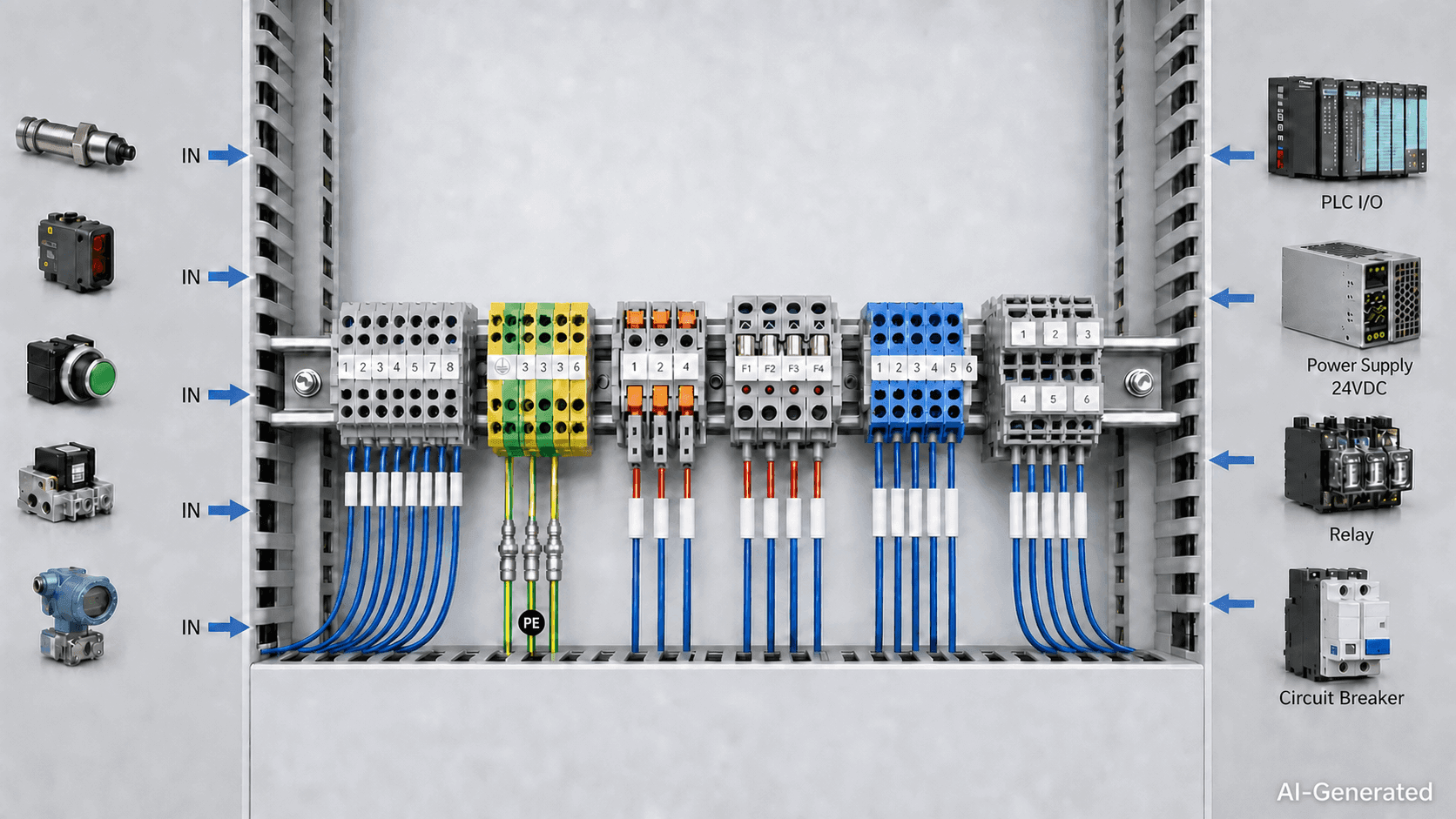
In a control cabinet, field wiring from sensors, switches, valves, and other equipment must be connected to PLC I/O, power supplies, relays, and protection devices. Without a defined termination point, wiring becomes harder to trace, test, and maintain.
DIN rail terminal blocks provide a structured interface between field wiring and internal cabinet circuits. Depending on the application, a terminal strip may include feed-through, PE, disconnect, fuse, distribution, or multi-level terminals.
Selecting one involves more than matching the wire size. Rated voltage and current, conductor type, connection method, DIN rail profile, available space, environmental conditions, and maintenance requirements also need to be checked.
What Is a DIN Rail Terminal Block?
In the previous section, we introduced what a terminal block is—a modular electrical connection component used to terminate and organize conductors while providing a reliable connection point between different parts of a circuit. A DIN rail terminal block follows the same basic principle, but is specifically designed to be mounted on a standardized DIN rail inside control cabinets and electrical enclosures.
A DIN rail terminal block provides a fixed connection point between field wiring and the circuits inside a control cabinet. Unlike a standalone wire connector, it is designed to form part of a modular terminal assembly. Multiple terminals can be installed side by side, with end stops, end plates, separators, markers, and jumpers added as required by the circuit layout.
The key difference is therefore the mounting method. DIN rail terminal blocks are designed around specific rail profiles rather than being used as standalone connectors. IEC 60715 defines several rail profiles, including TH15, TH35, C-section, and G-section types. The widely used 35 mm top-hat rail is therefore only one of several standardized rail arrangements.
For this reason, the terminal block and DIN rail profile should be checked together before installation to ensure mechanical compatibility and proper mounting.
How DIN Rail Mounting Works
Most DIN rail terminal blocks have a mounting foot on the underside of the housing. Depending on the design, one side hooks onto the rail while the opposite side snaps into position.
Adjacent terminals can then be installed side by side to form a terminal strip. End stops prevent the assembly from moving along the rail, while end plates and separators provide the required separation at the ends or between specific circuits.
A typical arrangement is:
End stop → feed-through terminals → PE terminal → disconnect terminal → end plate
The DIN rail is mainly used as a mechanical mounting structure. It should not be treated as an electrical conductor unless the terminal is specifically designed to make electrical contact with it. PE terminals are one common example.
Main Components of a DIN Rail Terminal Block
Although construction varies between terminal types, most designs contain four basic elements: an insulating housing, a conductive path, a clamping mechanism, and a mounting interface.
| Component | Function |
| Insulating housing | Provides electrical separation between adjacent terminals |
| Conductive element | Carries current between connected conductors |
| Clamping mechanism | Applies contact force and retains the conductor |
| Mounting foot | Secures the terminal to the DIN rail |
| Wire entry | Guides the conductor into the connection point |
| Marker holder | Provides terminal or circuit identification |
| Jumper interface | Allows selected terminals to share an electrical potential |
| Test point | Provides test access on applicable designs |
The housing is commonly made from an engineering thermoplastic selected for its electrical insulation and temperature characteristics. Current-carrying parts are typically copper or a copper alloy, with the material and surface finish depending on the electrical and environmental requirements.
Not every terminal includes all of these features. PE, fuse, disconnect, and distribution terminals, for example, have additional elements related to their specific functions.
How Electrical and Mechanical Connections Work
A terminal block has to maintain a reliable electrical path while keeping the conductor securely in place. The way this is achieved depends on the connection design.
Screw-clamp terminals use a screw to apply force to the conductor or an intermediate clamping element. The specified tightening torque is part of the connection design and should be followed during installation.
Spring-clamp terminals use a spring element to maintain contact pressure on the conductor. The spring provides the clamping force without relying on a screw remaining at a particular torque.
Push-in terminals use a spring mechanism that allows compatible conductors to be inserted directly. Depending on the design, a release tool may be required when removing the conductor.
The connection method affects wire preparation, installation, testing, and future maintenance. Stripping length, conductor cross-section, conductor type, ferrule compatibility, and termination method should therefore be checked against the manufacturer's technical data.
For screw-clamp terminals, both insufficient and excessive tightening can cause problems. Too little contact force may increase contact resistance, while excessive torque can damage the clamping system or conductor.
Common Types of DIN Rail Terminal Blocks
DIN rail terminal blocks are available in different configurations because the terminal strip may need to do more than join two wires. Some terminals provide a simple electrical path, while others add grounding, circuit isolation, fuse protection, power distribution, or higher wiring density.
The most common terminal block types are outlined below.
Feed-Through Terminal Blocks
A feed-through terminal block provides a direct connection between two conductors. It is the standard choice for general control-panel and field-wiring applications.
One side can connect to PLC or internal cabinet wiring, while the other connects to a sensor, actuator, or external circuit.
When selecting a feed-through terminal, check the conductor range, rated voltage and current, connection method, and applicable approvals.
Ground / PE Terminal Blocks
A PE terminal block provides a connection for protective conductors and is designed for integration with the protective-earth system.
Depending on the design, the terminal establishes electrical contact with the conductive DIN rail when correctly mounted. This can allow the DIN rail to become part of the protective-earth path when the rail and mounting arrangement are designed and installed accordingly.
PE terminals are used for:
- Protective-earth conductors
- Machine-frame bonding
- Control cabinet grounding
- Equipment grounding
They should not be replaced with ordinary feed-through terminals. PE terminals have specific construction and electrical requirements covered by standards such as IEC 60947-7-2.
The exact protective-earth path depends on the terminal and rail design. Always verify the manufacturer's grounding specification and installation requirements.
Disconnect Terminal Blocks
A disconnect terminal block provides a means of opening a circuit without removing the conductor from the terminal.
The disconnect function may use a removable link, knife contact, lever, or plug, depending on the design. These terminals are useful where circuits need to be isolated during commissioning, testing, or maintenance.
For instrumentation and PLC I/O, a disconnect terminal can save time during troubleshooting because the field conductor remains terminated while the circuit is opened at the terminal.
Fuse Terminal Blocks
A fuse terminal block combines wire termination with overcurrent protection in a single terminal.
They are commonly used for individual 24 VDC control circuits, sensors, relays, and instrumentation. Compared with installing a separate fuse holder, a fuse terminal can reduce wiring and panel space.
Selection should account for the fuse type and size as well as the terminal's voltage, current, and conductor ratings.
Double-Level Terminal Blocks
A double-level terminal block places two independent connection levels within one housing.
Its main advantage is wiring density. Two circuits can occupy less DIN rail space than two conventional single-level terminals.
The compromise is accessibility. Upper and lower connection points can be more difficult to reach after the panel is fully wired. Double-level terminals are therefore most useful where space is limited and the circuits do not require frequent access.
What Are DIN Rail Terminal Blocks Used for?
DIN rail terminal blocks are commonly used in control cabinets, automation equipment, and electrical enclosures where field wiring needs to be terminated, organized, and connected to internal control circuits.
Typical applications include:
- PLC and I/O control panels
- Industrial automation machinery
- Machine tools
- Motor control cabinets
- Process control and instrumentation
- HVAC and building automation
- Low-voltage power distribution
In a PLC cabinet, field cables from sensors, switches, valves, and actuators typically enter the enclosure and terminate at a terminal strip. Short internal conductors then connect the terminals to the PLC, relay, power supply, or other panel components.
For example:
Field sensor → terminal block → PLC input
PLC output → terminal block → actuator
This arrangement creates a clear boundary between field wiring and internal cabinet wiring. It also gives technicians an accessible point for wire identification, electrical testing, circuit isolation, and maintenance without disturbing the field connection.
Terminal blocks are also useful for organizing larger control panels. Terminals can be grouped according to circuit function, such as power, digital I/O, analog signals, or protective conductors. This makes the wiring easier to follow and leaves a defined interface for commissioning or future modifications.
In compact cabinets, terminal selection can also affect panel layout. Double-level or other high-density configurations may reduce DIN rail space, while dedicated disconnect or fuse terminals can combine termination with additional circuit functions.
The final arrangement depends on the control architecture, conductor requirements, available cabinet space, and how the equipment will be tested and maintained.
DIN Rail Terminal Block Sizes, Ratings, and Specifications
Terminal dimensions have a direct effect on panel layout, but size alone is not enough to select a terminal.
DIN Rail Profile
The terminal mounting foot has to match the rail profile.
IEC 60715 defines several mounting rail profiles. For top-hat rails, examples include TH15 and TH35; Common 35 mm top-hat rail variants include TH35-7.5 and TH35-15. Other profiles, including G-section rails, are also defined.
For this reason, the rail specification should be checked before selecting the terminal.
Terminal Width and Pitch
Terminal width determines how much rail length each position occupies.
If a terminal is 6 mm wide and a terminal strip contains 20 positions:
6 mm × 20 = 120 mm
That is only the basic terminal footprint. End stops, end plates, separators, jumpers, and required clearances can add to the final space requirement.
Actual commercial terminal widths vary considerably with conductor capacity and product design. Current product catalogs, for example, list feed-through terminals around 5–6 mm wide alongside wider versions for different conductor ranges.
Pitch and access also matter. A very narrow terminal strip saves rail space, but the available room for wire insertion, screwdriver access, and testing becomes smaller.
Wire Size and Conductor Type
The terminal must be suitable for the conductor actually being installed.
Check the manufacturer's data for:
- Minimum and maximum cross-section
- Solid conductor range
- Stranded conductor range
- Fine-stranded conductor range
- Ferrule compatibility
- AWG range
- Number of conductors allowed per terminal
Do not select a terminal simply because the wire fits into the opening.
The conductor range, rated current, connection method, and applicable test conditions all form part of the terminal's specification.
Rated Voltage and Current
Rated voltage and current are usually the first electrical specifications engineers check.
IEC 60947-7-1 covers terminal blocks and test-disconnect terminal blocks with screw-type or screwless clamping units for copper conductors. The current edition covers a broad range of conductor sizes and electrical applications within the standard's defined scope.
The rated current should not be interpreted as an unconditional operating limit.
Actual performance can depend on:
- Ambient temperature
- Conductor cross-section
- Contact resistance
- Number of adjacent loaded terminals
- Heat dissipation
- Installation arrangement
- Manufacturer's derating data
For a high-current terminal strip, check the manufacturer's temperature-rise and derating information before finalizing the design.
Temperature and Environmental Conditions
A terminal installed inside a clean control cabinet has different requirements from one installed on a machine exposed to vibration, oil, dust, or temperature changes.
Consider:
- Operating temperature
- Temperature cycling
- Vibration
- Shock
- Humidity
- Dust
- Oil and chemicals
- Flammability requirements
The enclosure environment should be considered together with the terminal's material and electrical rating.
Applicable Standards and Approvals
Common standards for DIN rail terminal blocks include:
- IEC 60947-7-1:2025 — Terminal blocks for copper conductors
- IEC 60947-7-2 — Protective conductor terminal blocks
- UL 1059 — Terminal blocks
- CSA C22.2 No. 158-2023 — Terminal blocks
IEC 60947-7-1:2025 is the fourth edition and replaces the 2009 edition. The 2025 revision expands the scope to smaller conductor cross-sections and introduces AWG conductor sizes as equivalent conductor types, along with other technical revisions.
For protective conductor terminals, IEC 60947-7-2:2009 specifies requirements for terminal blocks with PE and PEN functions.
In North America, UL 1059 and CSA C22.2 No. 158 are commonly referenced for terminal blocks. The applicable standard and approval depend on the product design, intended application, and target market.
DIN rail compatibility alone does not indicate that a terminal block meets a particular certification or approval requirement. Always verify the manufacturer's technical documentation and the approval markings for the specific product.
What Is a DIN Rail Terminal Connector?
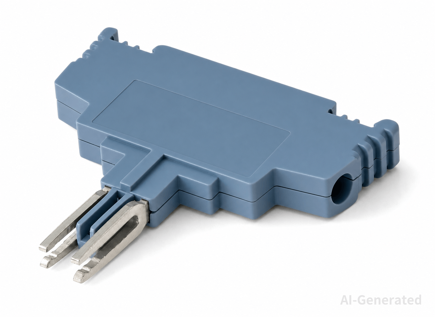
DIN rail terminal connector is a product term commonly used for a terminal block designed to mount on a DIN rail. In catalogs and online searches, the terms DIN rail terminal connector and DIN rail terminal block are often used interchangeably.
The important distinction is not the name but the product configuration. A suitable terminal must match the rail, conductor, electrical load, and required connection method.
Different designs may provide additional functions such as disconnecting, fusing, grounding, or power distribution. For that reason, products with similar names should not be assumed to be interchangeable.
When comparing a DIN rail terminal connector, check the manufacturer's dimensional drawing and technical specifications. The mounting profile, conductor capacity, electrical ratings, connection technology, and compatible accessories determine whether a particular terminal is suitable for the installation.
How to Use a Terminal Block Connector
Using a terminal block connector involves more than inserting a wire. Correct conductor preparation and installation are important for maintaining a reliable connection.
Prepare the Wire
Cut the conductor to the required length and strip the insulation according to the terminal manufacturer's specified stripping length.
For stranded conductors, keep the strands intact. If a ferrule is required or permitted, use the correct size and crimp it properly before insertion.
Install the Terminal
Mount the terminal on the specified DIN rail and position it according to the panel drawing.
For a terminal assembly, install the required end stops, end plates, separators, and jumpers. Make sure adjacent terminals are arranged in the intended circuit order before wiring begins.
Connect the Conductor
Insert the prepared conductor fully into the connection point.
For screw-clamp designs, tighten the terminal to the specified torque. Spring-clamp and push-in designs should be operated according to the manufacturer's instructions.
After connection, check that the conductor is securely retained and that no excessive bare copper is exposed.
Identify and Inspect
Apply the terminal and wire markers according to the electrical documentation.
Before energizing the circuit, inspect the completed connection for correct terminal position, conductor engagement, jumper placement, and identification. Where required, perform a continuity, polarity, or functional check.
For larger terminal assemblies, checking the completed wiring against the schematic before commissioning can prevent wiring errors from being carried into the next stage of testing.
How to Wire DIN Rail Terminal Blocks
DIN rail terminal block wiring should be planned from the electrical schematic rather than from the physical layout of the cabinet. The terminal strip acts as the interface between field cables and internal panel wiring, so each terminal should have a defined circuit function and reference.
A simple control circuit may follow:
Power source → protection → terminal strip → field device
For PLC I/O, the arrangement is typically:
PLC I/O → terminal strip → field device
The exact layout depends on the control architecture, but power, control, signal, and protective-conductor circuits should be organized so that they can be identified and serviced without confusion.
Basic Wiring Procedure
Before wiring, establish the terminal sequence from the electrical drawing and assign each terminal to its corresponding circuit.
A practical sequence is:
- Arrange the terminals in the order shown on the schematic.
- Separate power, control, signal, and PE connections where required.
- Connect common potentials using the manufacturer's compatible jumpers.
- Route field conductors and internal panel wires to their designated terminals.
- Verify terminal numbers and wire references against the drawing.
- Check continuity, polarity, and circuit separation where applicable.
- Inspect the completed terminal strip before energizing the panel.
This approach is particularly useful for larger PLC I/O wiring assemblies, where dozens or hundreds of similar connections may be present.
DIN Rail Terminal Block Wiring Practices
Good DIN rail terminal block wiring depends on matching the terminal, conductor, and circuit requirements rather than simply making the connection fit.
| Wiring consideration | What to check |
| Conductor selection | Verify conductor size, type, and the permitted number of conductors for the terminal. |
| Jumpers | Use jumpers designed for the terminal family and suitable for the circuit load. |
| Circuit separation | Keep power, control, signal, and PE circuits organized according to the electrical design. |
| Polarity and identification | Follow the schematic for positive, 0 V, signal, and terminal references rather than relying on wire color alone. |
| PE connections | Use dedicated PE terminals where protective-conductor connections are required. |
| Access and spacing | Leave sufficient room for testing, tools, markers, and future maintenance. |
| Final inspection | Check terminal numbers, jumpers, polarity, conductor engagement, and continuity before energizing. |
For larger control panels, organizing the terminal strip by circuit function can make commissioning and troubleshooting more straightforward. The final layout should provide enough wiring density to use the available DIN rail efficiently without making individual connections difficult to access.
Practical Example: PLC Control Panel
Consider a PLC control panel with 24 VDC control circuits, 1.5 mm² stranded conductors, and limited DIN rail space.
The terminal configuration should follow the circuit requirements:
- Basic field connection → feed-through terminal
- Circuit isolation → disconnect terminal
- Individual branch protection → fuse terminal
- Limited rail space → double-level terminal
If several circuits share the same supply potential, compatible jumpers can be used to simplify the distribution. The selected terminals must still meet the required conductor range and electrical ratings.
The example illustrates the basic selection principle: circuit function determines the terminal type, while wiring density and panel layout determine the configuration. The goal is not to use the smallest terminal available, but to achieve a reliable connection that remains accessible for testing and maintenance.
FAQs
What is the difference between a DIN rail terminal block and a regular terminal block?
The main difference is the mounting arrangement.
DIN rail terminal blocks use a mounting foot designed for a compatible DIN rail and are normally part of a modular terminal system. Other terminal blocks may be designed for PCB mounting, panel mounting, or direct equipment installation.
Can any terminal block be mounted on a DIN rail?
No. The terminal needs a mounting interface designed for the particular rail profile. A DIN rail terminal designed for TH35, for example, should not automatically be assumed to fit another rail profile.
Can different types of DIN rail terminal blocks be installed on the same rail?
Yes, provided the mounting system and accessories are compatible.
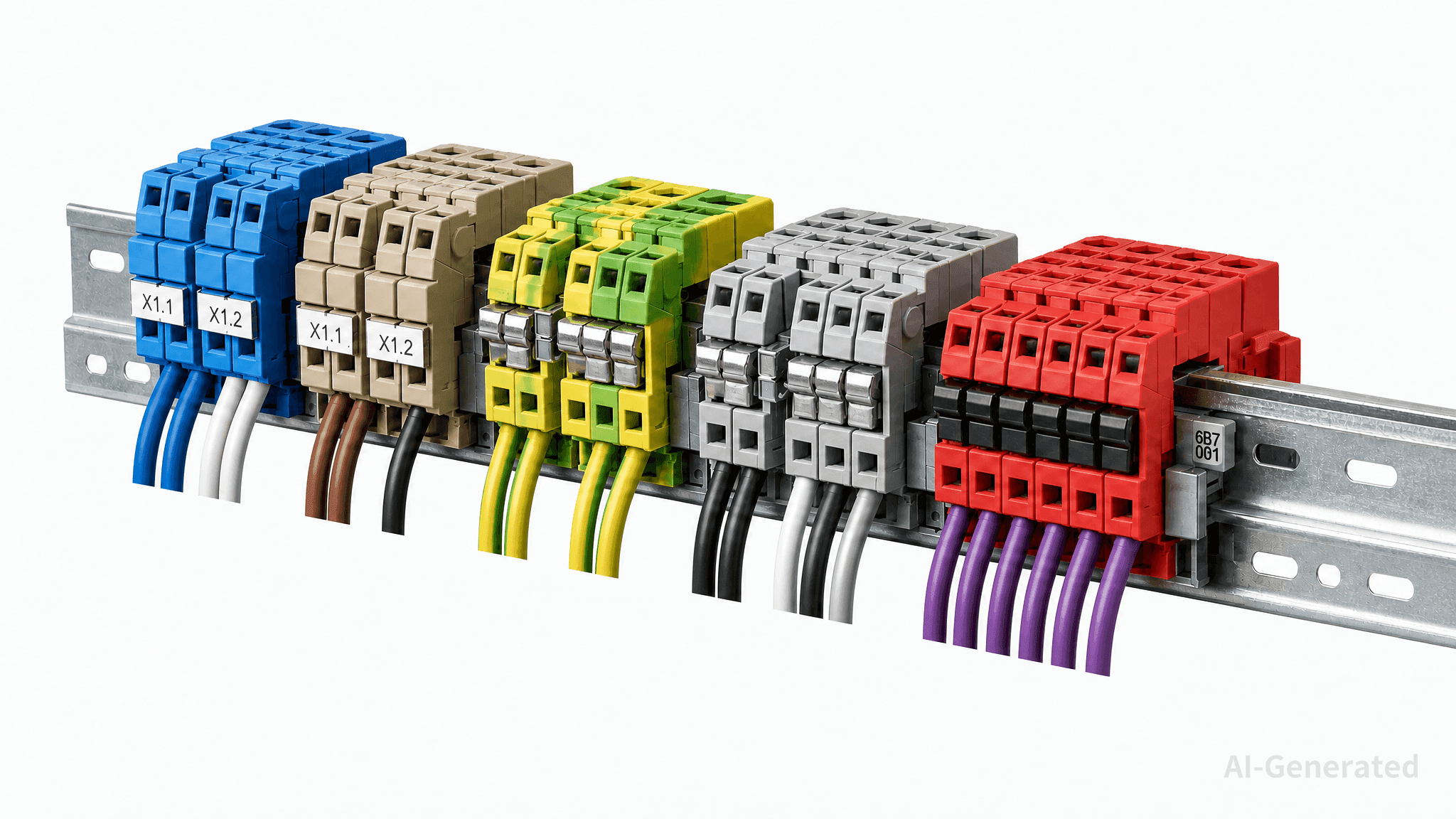
A single rail can contain feed-through, PE, fuse, disconnect, and other terminal types. The panel designer still needs to check electrical separation, terminal dimensions, jumpers, end plates, and other accessories.
How do I choose the right DIN rail terminal block?
Start with the circuit requirements: voltage, current, conductor size and type, and connection method. Then verify the terminal function, DIN rail profile, available space, environmental conditions, and applicable standards. For higher-current applications, also check the manufacturer's derating data.
In short:
Circuit → electrical ratings → conductor → function → rail → space → environment → standards
Conclusion
DIN rail terminal blocks provide a structured interface between field wiring and the circuits inside a control cabinet. The right configuration depends on the circuit function, conductor requirements, electrical ratings, DIN rail profile, available space, and installation environment.
For most applications, start with the voltage, current, and conductor size, then select the appropriate terminal type and connection method. Finally, verify rail compatibility, derating data, applicable standards, and access for testing and maintenance.
A well-selected terminal block should not only meet the electrical requirements but also support reliable wiring, clear identification, and efficient panel maintenance.
Keep Learning
A Complete Guide to DIN Rail Terminal Blocks
Introduction In a control cabinet, field wiring from sensors, switches, valves, and other equipment must be connected to PLC I/O, power supplies, relays, and protection devices. Without a defined termination point, wiring becomes harder to trace, test, and maintain. DIN rail terminal blocks provide a structured interface between field wiring and internal cabinet circuits. Depending on the application, a terminal strip may include feed-through, PE, disconnect, fuse, distribution, or multi-level termina......
How to Choose Between Screw, Spring, and Push-In Terminal Blocks
Introduction The connection method is more than a choice between a screw, a spring, or a push-in mechanism. It determines how clamping force is generated, how the conductor is retained, how the connection responds to vibration and temperature changes, and how much time is required for installation and maintenance. Screw-clamp, spring-clamp, and push-in terminal blocks can all provide reliable electrical connections when correctly specified. The difference is how each design achieves that connection an......
How to Select a Terminal Block: A Complete Selection Guide
Introduction Choosing the right terminal block requires more than matching voltage and current ratings. Terminal block selection also depends on wire size, conductor type, connection method, mounting configuration, available space, operating environment, and safety requirements. In control panels and industrial equipment, the terminal block must provide a reliable electrical connection while supporting efficient wiring, testing, and maintenance. A practical selection sequence is: Application → Voltage......
What Is a Terminal Block? Types, Working Principles, and Applications
Introduction A terminal block is a modular electrical connector used to securely connect and organize multiple wires in electrical systems. It provides a reliable connection point for power distribution, signal transmission, and circuit management. Commonly used in industrial automation, control panels, and electrical equipment, terminal blocks help improve wiring organization, simplify maintenance, and enhance system reliability. In this guide, you will learn what a terminal block is, how it works, t......
5 Common Pressure Sensor Problems and How to Troubleshoot Them
Introduction: In previous articles, we explored “What Is a Pressure Sensor?”, “Pressure Sensors Explained: Working Principles, Types, and Applications,” and “How to Select the Right Pressure Sensor,” covering the fundamentals of pressure sensors, including their working principles, types, applications, and key selection considerations. However, even a properly selected pressure sensor may encounter performance issues during operation due to factors such as wiring errors, improper installation, harsh e......
How to Select the Right Pressure Sensor?
Introduction: In previous articles, we explored “What Is a Pressure Sensor?” and “Pressure Sensors Explained: Working Principles, Types, and Applications,” covering the fundamentals of pressure sensors, including how they work, different sensor types, and their applications across industrial automation systems. However, understanding how pressure sensors work is only the first step. In real industrial applications, selecting the right pressure sensor requires engineers to consider multiple factors, in......