How to Choose Between Screw, Spring, and Push-In Terminal Blocks
15 min
- Introduction
- Screw, Spring, and Push-In Terminal Blocks: The Basic Principle
- Screw vs. Spring vs. Push-In: Key Engineering Differences
- Application → Requirement → Connection Method
- How Wire Type Affects Terminal Block Selection
- How Application Requirements Affect the Choice
- A Practical Decision Framework
- How to Read a Terminal Block Datasheet Before Choosing
- Common Selection Mistakes
- Terminal Block Connection Method Selection Checklist
- FAQs
- What is the difference between screw and push-in terminal blocks?
- Conclusion
Introduction
The connection method is more than a choice between a screw, a spring, or a push-in mechanism. It determines how clamping force is generated, how the conductor is retained, how the connection responds to vibration and temperature changes, and how much time is required for installation and maintenance.
Screw-clamp, spring-clamp, and push-in terminal blocks can all provide reliable electrical connections when correctly specified. The difference is how each design achieves that connection and how well it fits the application's electrical, mechanical, environmental, and production requirements.
A basic explanation of terminal block construction and connection methods is covered in our previous guide. This article focuses on the engineering trade-offs between the three methods and provides a practical framework for selecting the right one.
Screw, Spring, and Push-In Terminal Blocks: The Basic Principle
At a fundamental level, all three connection methods perform the same task: they apply mechanical force to maintain electrical contact between a conductor and a conductive element.
Push-in terminals are generally a type of spring-based connection that allows compatible conductors to be inserted directly into the clamping point.
The difference is how that force is generated:
- Screw-clamp: The installer creates clamping force by tightening a screw.
- Spring-clamp: An elastic spring element maintains the clamping force.
- Push-in: A spring-based mechanism clamps a compatible conductor as it is inserted.
This difference affects several downstream characteristics, including installation procedure, contact stability, conductor compatibility, and maintenance.
The selection should therefore begin with the application requirements rather than the connection mechanism itself.
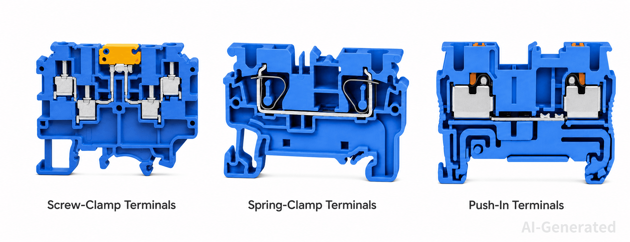
Screw vs. Spring vs. Push-In: Key Engineering Differences
Contact Force and Connection Reliability
A reliable terminal connection depends on maintaining sufficient contact pressure between the conductor and the conductive contact surface.
In a screw-clamp terminal, the initial clamping force depends on the tightening process. This makes installation torque an important parameter. Too little torque can result in insufficient contact pressure, while excessive torque can damage the conductor or terminal components.
Spring-clamp and push-in designs use an elastic element to establish the clamping force. Within the operating range of the spring, this allows the connection to accommodate small dimensional changes caused by conductor deformation, vibration, or temperature changes.
This does not mean that spring-based connections are automatically more reliable. Connection reliability also depends on:
- Contact geometry
- Conductive material
- Conductor preparation
- Clamping force
- Terminal construction
- Environmental conditions
- Correct installation
The engineering question is therefore not simply which connection method has the strongest clamping force, but whether the terminal can maintain the required electrical and mechanical performance throughout its intended service life.
Current, Temperature, and Derating
Connection method should not be evaluated separately from current-carrying performance.
When current flows through a conductor and its termination, electrical resistance generates heat. The resulting temperature rise depends on factors such as conductor size, contact resistance, terminal construction, ambient temperature, and current.
A terminal block's rated current therefore needs to be considered together with the actual operating conditions.
For example, an application operating continuously near the terminal's nominal current rating may require more attention to:
- Ambient temperature
- Conductor cross-section
- Number of adjacent loaded terminals
- Terminal temperature rise
- Applicable derating requirements
This is also why the connection method alone does not determine whether a terminal is suitable for high-current applications. Screw, spring, and push-in terminals are all available in different electrical configurations.
When comparing products, use the manufacturer's rated current and temperature data under the relevant installation conditions rather than assuming that one connection method inherently carries more current than another.
Wiring Speed
The three connection methods differ significantly in how much manual operation is required during installation.
A screw-clamp terminal normally requires the conductor to be positioned and the screw tightened. A spring-clamp terminal uses a spring mechanism to establish the connection, while a push-in terminal can allow a compatible conductor to be inserted directly.
For a small control panel, the difference may have little practical effect. For a production line assembling hundreds of cabinets, it can become a measurable labor factor.
The important comparison is therefore not simply:
Which terminal is fastest?
It is:
How much total labor is saved across wire preparation, connection, inspection, and future maintenance?
A push-in terminal may provide the fastest initial connection while a screw terminal may remain more economical where only a small number of wires are terminated.
Vibration and Thermal Cycling
Mechanical vibration and repeated temperature changes can alter the conditions at a conductor-terminal interface.
Vibration can introduce small relative movements between components, while thermal cycling causes materials to expand and contract at different rates.
Spring-based connection systems can accommodate some of these changes because the spring maintains a mechanical force over a defined displacement range.
Screw-clamp terminals can also provide reliable performance in vibration-prone applications when properly designed, installed, and specified. However, the initial tightening condition becomes particularly important.
For demanding environments, engineers should look for actual vibration, shock, and thermal performance data in the product documentation.
The practical trade-off is therefore:
- Screw: connection depends more directly on correct mechanical tightening.
- Spring: elastic clamping can help maintain contact force during mechanical and dimensional changes.
- Push-in: combines spring clamping with a fast insertion process, but conductor compatibility must be verified carefully.
Maintenance and Rewiring
The connection method also affects what happens after the original installation.
Screw-clamp terminals are familiar to most technicians and provide straightforward access to the clamping screw. However, maintenance procedures may require torque verification.
Spring and push-in terminals generally reduce dependence on manual retightening because the spring provides the clamping force.
For equipment that is frequently modified, another factor becomes important: how easily the conductor can be released without disturbing neighboring connections.
Maintenance should therefore be evaluated in terms of:
- Connection inspection
- Wire removal
- Reconnection
- Testing access
- Required tools
- Retightening requirements
- Risk of disturbing adjacent conductors
- A terminal that is fast to install but difficult to service may not provide the best overall solution.
Conductor Compatibility
The connection mechanism must match the actual conductor construction.
Important variables include:
- Solid conductor
- Stranded conductor
- Fine-stranded conductor
- Ferruled conductor
- Conductor cross-section
- AWG size
- Stripping length
This is particularly important when comparing push-in terminals.
A push-in terminal may accept a solid conductor directly but specify a different preparation method for stranded conductors. Another design may allow direct insertion of certain stranded conductors or require ferrules.
Therefore, "1.5 mm² compatible" is not by itself a complete compatibility statement.
The conductor construction and preparation requirements must also match the manufacturer's specifications.
Installation Density and Accessibility
Terminal density is influenced by more than terminal width.
The practical installation envelope also includes:
- Wire-entry direction
- Conductor bending radius
- Adjacent terminal spacing
- Tool access
- Test-probe access
- Marking space
- Maintenance clearance
Push-in terminals can be advantageous where a large number of connections must be installed in limited panel space.
However, maximizing terminal density can create another problem: poor accessibility.
A well-designed terminal assembly should balance compactness with the ability to inspect, test, remove, and replace conductors.
Application → Requirement → Connection Method
The most useful way to compare connection technologies is to start with the application and identify the requirement that drives the decision.
| Application | Primary Engineering Requirement | Connection Method to Consider |
| PLC I/O wiring | High connection count, fast assembly | Push-in / Spring |
| General control cabinet | Versatility, maintenance access | Screw / Spring / Push-in |
| High-volume panel production | Reduced assembly labor | Push-in |
| Vibration-prone machinery | Verified vibration and shock performance | Spring / Push-in / Screw, depending on tested performance |
| Frequently modified equipment | Easy connection and reconnection | Application-dependent |
| Power distribution | Current, temperature rise, conductor size | Application-dependent |
| High-density wiring | Compact layout and accessibility | Push-in / Spring |
| Conventional low-volume wiring | Familiar installation and broad compatibility | Screw |
This table should be treated as a starting point, not a product-selection rule.
For example, a PLC cabinet does not automatically require push-in terminals. If the conductors, maintenance procedure, environmental conditions, or electrical ratings favor another design, that should take priority.
How Wire Type Affects Terminal Block Selection
Solid Conductors
Solid conductors generally maintain their shape during insertion and are accepted by many terminal designs.
For push-in applications, verify the specified conductor size and stripping length before installation.
Stranded Conductors
Stranded conductors provide flexibility but can behave differently during termination.
The individual strands can spread or deform if the conductor is not prepared correctly.
Check whether the terminal permits direct insertion or requires a ferrule or another preparation method.
Fine-Stranded Conductors
Fine-stranded conductors contain more, smaller strands and are often selected where repeated movement or flexibility is required.
Their compatibility should be explicitly confirmed because the termination behavior differs from that of solid conductors and conventional stranded wire.
Ferruled Conductors
Ferrules consolidate stranded conductors into a defined termination geometry, improving consistency when inserting the conductor into the terminal. However, ferrules are not universally required and add an additional conductor-preparation step before installation.
Check the manufacturer's specifications for whether ferrules are permitted, recommended, or required for the specific conductor type and cross-section.
Wire Preparation Matters
Correct conductor preparation is part of the connection system.
Check:
- Stripping length
- Conductor insertion depth
- Ferrule dimensions
- Crimp quality
- Exposed conductor length
- Condition of individual strands
A correctly selected terminal can still produce a poor connection if the conductor is improperly prepared.
How Application Requirements Affect the Choice
Industrial Automation and PLC Systems
PLC systems often involve a large number of control and I/O connections.
Here, wiring productivity and terminal identification can have a significant impact on panel assembly.
Push-in terminals can be attractive when repetitive wiring is a major part of production. Spring-clamp terminals are also worth considering where vibration resistance and stable clamping force are important.
For systems that are frequently modified, the release mechanism and maintenance procedure should also be evaluated.
Control Cabinets
Control cabinets frequently combine signal, control, and power circuits.
There is no requirement to use one connection method throughout the cabinet.
The better approach is to select each terminal according to its circuit requirements, conductor size, wiring volume, and maintenance needs.
Power Distribution Systems
Power applications require particular attention to:
- Rated current
- Rated voltage
- Conductor cross-section
- Temperature rise
- Ambient temperature
- Derating
- Applicable standards
Connection speed should be secondary to electrical suitability.
A push-in terminal should not be selected for a power circuit simply because it is faster to wire.
Machine Building
Machine builders often need to balance assembly efficiency with vibration resistance, limited panel space, and future maintenance.
Spring and push-in systems can be attractive when repetitive wiring is involved, while screw-clamp terminals may remain practical for lower-volume or frequently modified assemblies.
Vibration-Prone Equipment
For equipment exposed to continuous vibration or mechanical shock, evaluate:
- Clamping mechanism
- Contact stability
- Vibration test data
- Shock performance
- Conductor retention
- Installation requirements
A spring-based mechanism may offer useful mechanical advantages, but the specific terminal's tested performance should determine the final decision.
High-Density Wiring Systems
High-density applications require a balance between compact terminal dimensions and serviceability.
A compact terminal is useful only if technicians can still access the conductor, perform electrical testing, and replace wires without excessive disassembly.
A Practical Decision Framework
Choose the connection method based on the application, not on the mechanism alone. The following steps cover the main factors that affect terminal block selection.
Step 1: Define the Electrical Requirements
Start with the operating voltage, continuous current, conductor size, ambient temperature, and any peak loads. Eliminate terminals that do not meet the required electrical ratings or operating conditions.
Step 2: Identify the Conductor
Check whether the application uses solid, stranded, fine-stranded, or ferruled conductors. Confirm the permitted wire size, conductor type, ferrule compatibility, and stripping length in the manufacturer's specifications.
Step 3: Evaluate the Mechanical Environment
Consider vibration, shock, thermal cycling, and equipment movement. Where mechanical stress is significant, compare the terminal's clamping mechanism and relevant vibration or shock data.
Step 4: Consider Wiring Volume
For a small number of connections, wiring speed may have little impact on total cost. In high-volume panel production, however, the time saved with spring or push-in connections can make a noticeable difference in labor.
Step 5: Consider Maintenance
Think beyond the initial installation. If the equipment will be frequently serviced or rewired, check how easily conductors can be released, reconnected, tested, and accessed.
Step 6: Check Panel Space
Look at terminal width, wire routing, bending radius, tool access, and maintenance clearance together. High-density wiring saves space, but excessive density can make testing and servicing more difficult.
Step 7: Verify the Datasheet
Use the manufacturer's datasheet to confirm the final selection. Check the electrical ratings, conductor specifications, installation requirements, environmental limits, and applicable approvals before ordering.
How to Read a Terminal Block Datasheet Before Choosing
A datasheet is most useful when each specification is interpreted in the context of the application.
Electrical Ratings: Can It Handle the Circuit?
Check:
- Rated voltage
- Rated current
- Rated cross-section
- Temperature rise
- Derating information
Do not compare the rated current in isolation.
For a continuous-current application, determine whether the rating applies under the intended ambient temperature, conductor size, and installation arrangement.
Conductor Specifications: Will It Accept the Actual Wire?
Check:
- Solid conductor range
- Stranded conductor range
- Fine-stranded conductor range
- Ferrule compatibility
- AWG range
- Metric cross-section
- Stripping length
- If the application uses fine-stranded or ferruled conductors, do not rely on the general wire-size range alone.
Mechanical Specifications: Will It Survive and Fit?
Check:
- Terminal width
- Mounting method
- Conductor retention
- Installation torque
- Wire-entry direction
- Required tools
- Vibration and shock specifications
These parameters determine whether the terminal can be installed correctly and remain mechanically suitable in service.
Environmental and Safety Specifications: Is It Suitable for the Location?
Review:
- Operating temperature
- Pollution degree
- Insulation characteristics
- Flammability rating
- Vibration and shock performance
- Certifications and approvals
The required specifications depend on the installation environment and applicable regulations.
Common Selection Mistakes
Selecting by Component Price Alone
The purchase price of the terminal is only one part of the total cost.
For high-volume wiring, installation labor can have a greater impact on overall cost than a small difference in component price.
Selecting by Wiring Speed Alone
A fast connection is useful only if the terminal also meets the electrical, conductor, mechanical, and environmental requirements.
Assuming Equivalent Wire Sizes Are Equivalent
A 1.5 mm² solid conductor and a 1.5 mm² fine-stranded conductor may have different termination requirements.
Always check conductor construction.
Treating Connection Type as a Guarantee of Vibration Performance
Spring-based designs can provide advantages under vibration, but actual performance depends on the complete terminal design and test data.
Ignoring Thermal Conditions
Rated current should be considered together with ambient temperature, conductor size, temperature rise, and applicable derating.
Assuming Push-In Means Completely Tool-Free
Insertion may be tool-free for compatible conductors, while conductor release or specific conductor preparations may still require a tool.
Ignoring Installation Torque
For screw-clamp terminals, correct torque is part of the connection specification.
Using Terminal Width as the Only Density Metric
A narrow terminal does not automatically produce a better panel layout. Wire routing, testing, and maintenance access must also be considered.
Terminal Block Connection Method Selection Checklist
Before finalizing a terminal block, check the following:
- Electrical: Rated voltage, current, temperature limits, and derating.
- Conductor: Wire size and type, ferrule compatibility, and stripping length.
- Mechanical: Vibration, shock, and thermal cycling requirements.
- Installation: Terminal size, wire routing, tool access, and maintenance space.
- Wiring: Expected connection volume and the practicality of the selected connection method.
- Installation requirements: Torque and other manufacturer-specified installation conditions.
- Compliance: Datasheet requirements, certifications, and applicable standards.
FAQs
What is the difference between screw and push-in terminal blocks?
Screw terminals use a manually tightened screw to generate clamping force, while push-in terminals generally use a spring mechanism that clamps a compatible conductor during insertion. The main practical differences are installation speed, torque requirements, conductor compatibility, and maintenance procedures.
Are spring terminal blocks better for vibration?
Spring-based terminals can maintain contact force as the connection experiences certain mechanical and dimensional changes, making them useful in many vibration-prone applications. However, actual performance depends on the terminal design and manufacturer's vibration and shock test data.
Can stranded wire be used with push-in terminal blocks?
Yes, if the terminal is specified for the particular stranded conductor. Some products accept certain stranded conductors directly, while others require ferrules or specific conductor preparation.
Do push-in terminal blocks require ferrules?
Not always. Ferrule requirements depend on the terminal design and conductor type. Always follow the manufacturer's conductor specifications.
Are push-in terminal blocks suitable for high-current applications?
They can be, provided the specific terminal is rated for the required current, conductor size, temperature conditions, and applicable installation requirements. Connection method alone does not determine current-carrying capacity.
Conclusion
Screw-clamp, spring-clamp, and push-in terminal blocks differ mainly in how they generate and maintain clamping force, which affects installation, connection stability, and maintenance.
A practical selection should consider:
Electrical requirements → conductor type → mechanical environment → wiring volume → maintenance → panel space → datasheet
Screw-clamp terminals offer familiar installation and broad compatibility. Spring-clamp designs can be useful where stable clamping and mechanical resistance matter, while push-in terminals are well suited to applications with high wiring volume and a need for faster assembly.
The final choice should be based on the actual electrical, mechanical, conductor, and installation requirements of the application.
Keep Learning
A Complete Guide to DIN Rail Terminal Blocks
Introduction In a control cabinet, field wiring from sensors, switches, valves, and other equipment must be connected to PLC I/O, power supplies, relays, and protection devices. Without a defined termination point, wiring becomes harder to trace, test, and maintain. DIN rail terminal blocks provide a structured interface between field wiring and internal cabinet circuits. Depending on the application, a terminal strip may include feed-through, PE, disconnect, fuse, distribution, or multi-level termina......
How to Choose Between Screw, Spring, and Push-In Terminal Blocks
Introduction The connection method is more than a choice between a screw, a spring, or a push-in mechanism. It determines how clamping force is generated, how the conductor is retained, how the connection responds to vibration and temperature changes, and how much time is required for installation and maintenance. Screw-clamp, spring-clamp, and push-in terminal blocks can all provide reliable electrical connections when correctly specified. The difference is how each design achieves that connection an......
How to Select a Terminal Block: A Complete Selection Guide
Introduction Choosing the right terminal block requires more than matching voltage and current ratings. Terminal block selection also depends on wire size, conductor type, connection method, mounting configuration, available space, operating environment, and safety requirements. In control panels and industrial equipment, the terminal block must provide a reliable electrical connection while supporting efficient wiring, testing, and maintenance. A practical selection sequence is: Application → Voltage......
What Is a Terminal Block? Types, Working Principles, and Applications
Introduction A terminal block is a modular electrical connector used to securely connect and organize multiple wires in electrical systems. It provides a reliable connection point for power distribution, signal transmission, and circuit management. Commonly used in industrial automation, control panels, and electrical equipment, terminal blocks help improve wiring organization, simplify maintenance, and enhance system reliability. In this guide, you will learn what a terminal block is, how it works, t......
5 Common Pressure Sensor Problems and How to Troubleshoot Them
Introduction: In previous articles, we explored “What Is a Pressure Sensor?”, “Pressure Sensors Explained: Working Principles, Types, and Applications,” and “How to Select the Right Pressure Sensor,” covering the fundamentals of pressure sensors, including their working principles, types, applications, and key selection considerations. However, even a properly selected pressure sensor may encounter performance issues during operation due to factors such as wiring errors, improper installation, harsh e......
How to Select the Right Pressure Sensor?
Introduction: In previous articles, we explored “What Is a Pressure Sensor?” and “Pressure Sensors Explained: Working Principles, Types, and Applications,” covering the fundamentals of pressure sensors, including how they work, different sensor types, and their applications across industrial automation systems. However, understanding how pressure sensors work is only the first step. In real industrial applications, selecting the right pressure sensor requires engineers to consider multiple factors, in......