How to Select a Terminal Block: A Complete Selection Guide
14 min
- Introduction
- 1.Define the Application Requirements
- 2.Check the Key Electrical Specifications
- 3.Match the Terminal to the Conductor
- 4.Choose the Connection Technology
- 5.Select the Mounting Configuration
- 6.Evaluate the Operating Environment
- 7.Verify Standards and Certifications
- 8.Consider Terminal Block Accessories
- 9.How to Read a Terminal Block Datasheet
- 10.Practical Example: Selecting a Terminal Block for a PLC Control Panel
- 11.Common Terminal Block Selection Mistakes
- FAQs
- Conclusion
Introduction
Choosing the right terminal block requires more than matching voltage and current ratings. Terminal block selection also depends on wire size, conductor type, connection method, mounting configuration, available space, operating environment, and safety requirements.
In control panels and industrial equipment, the terminal block must provide a reliable electrical connection while supporting efficient wiring, testing, and maintenance.
A practical selection sequence is:
Application → Voltage & Current → Wire Size → Connection Method → Mounting → Environment → Standards
This guide explains how to select a terminal block for control panels, PLC systems, power distribution, electronic equipment, and other industrial applications.
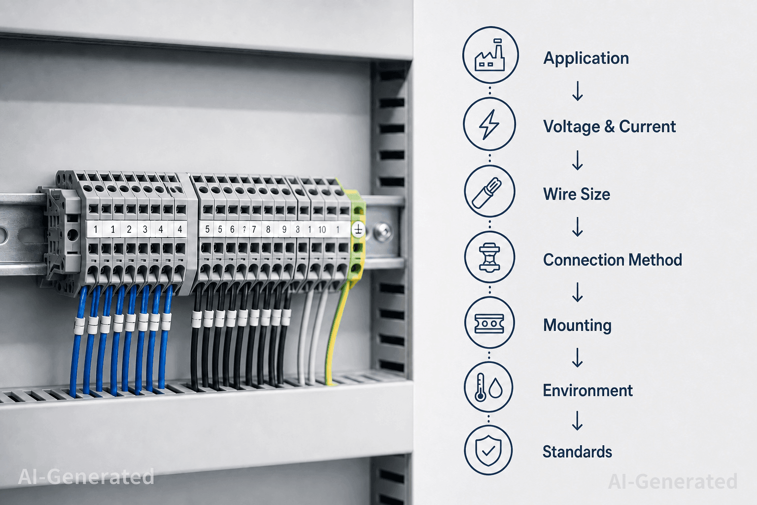
1.Define the Application Requirements
Before comparing terminal blocks, define the requirements of the circuit and installation. The application, electrical load, conductor, connection method, mounting conditions, environment, and compliance requirements will determine which specifications matter most.
| Requirement | What to Define |
| Application | PLC, control, power distribution, PCB, instrumentation, etc. |
| Electrical | Working voltage and continuous current |
| Conductor | Wire size and conductor type |
| Connection | Screw, spring-clamp, push-in, etc. |
| Mounting | DIN rail, PCB, or panel |
| Environment | Temperature, vibration, moisture, chemicals |
| Compliance | Applicable standards and certifications |
The priorities vary by application. A PLC control panel may place more emphasis on compact size, wiring density, and maintenance access, while a power distribution circuit may require greater attention to current capacity, conductor size, temperature rise, and electrical spacing.
Once these requirements are defined, use them to narrow down the terminal block specifications and configurations.
2.Check the Key Electrical Specifications
With the application requirements established, compare the terminal block's electrical ratings with the actual circuit conditions.
Rated Voltage
The terminal block's rated voltage should meet the working voltage of the circuit under the specified conditions. For higher-voltage applications, the rated voltage must be evaluated together with the applicable insulation, creepage, clearance, pollution degree, and overvoltage requirements.
Do not rely on the headline voltage rating alone. Check the conditions and standards associated with the published value.
Rated Current and Temperature Rise
The rated current should be evaluated together with the conditions under which it was specified. Temperature rise can be affected by conductor size, ambient temperature, contact resistance, the number of adjacent loaded terminals, and the terminal's installation conditions.
For continuous loads operating near the rated current, review the manufacturer's temperature-rise data and any applicable derating information.
The key question is not simply whether the load is below the rated current, but whether the terminal can carry that load under the actual operating conditions.
Insulation and Electrical Spacing
The insulating housing separates conductive parts and contributes to the terminal's electrical and mechanical performance. Common housing materials include polyamide (PA), polycarbonate (PC), and PBT, although their properties vary by product.
For higher-voltage or contaminated environments, check:
- Clearance — the shortest distance through air between conductive parts
- Creepage — the shortest distance along the surface of an insulating material between conductive parts
- Insulation requirements
- Pollution conditions
- Flammability and temperature ratings where applicable
The required values depend on the application and applicable standards. Use the manufacturer's specifications for the specific terminal block model.
3.Match the Terminal to the Conductor
The terminal block must be compatible with the conductor used in the application. Check the specified AWG or mm² range and confirm the permitted conductor construction.
Wire Size and Conductor Type
Do not select a terminal based only on its maximum wire size. The actual conductor must fall within the specified range, and the terminal must support its construction.
Common options include:
- Solid wire
- Stranded wire
- Fine-stranded wire
- Ferruled conductors
For example, a terminal specified for 0.5–2.5 mm² conductors can accept a 1.5 mm² conductor only if the conductor construction is also supported by the manufacturer.
Ferrule Compatibility
Ferrules can be useful with stranded conductors, particularly in control-panel wiring, but their use depends on the terminal design.
If ferrules are used, verify the:
- Conductor cross-section
- Ferrule size and length
- Required insertion depth
- Compatibility with the clamping mechanism
Follow the manufacturer's termination instructions rather than assuming that a ferrule is required or permitted for every connection.
Number of Conductors and Terminal Configuration
The wiring layout may call for more than a standard single-level feed-through terminal. Depending on the application, options include:
- Feed-through terminals
- Multi-level terminals
- Ground terminals
- Disconnect terminals
- Fuse terminals
- Multi-conductor terminals
Multi-level terminals can increase wiring density, while disconnect or test terminals can simplify circuit isolation and measurement during maintenance. Select the configuration based on the wiring scheme and service requirements.
4.Choose the Connection Technology
Connection technology affects wiring speed, conductor compatibility, maintenance procedures, and mechanical retention.
The right choice depends on the application rather than on a universal ranking of connection types.
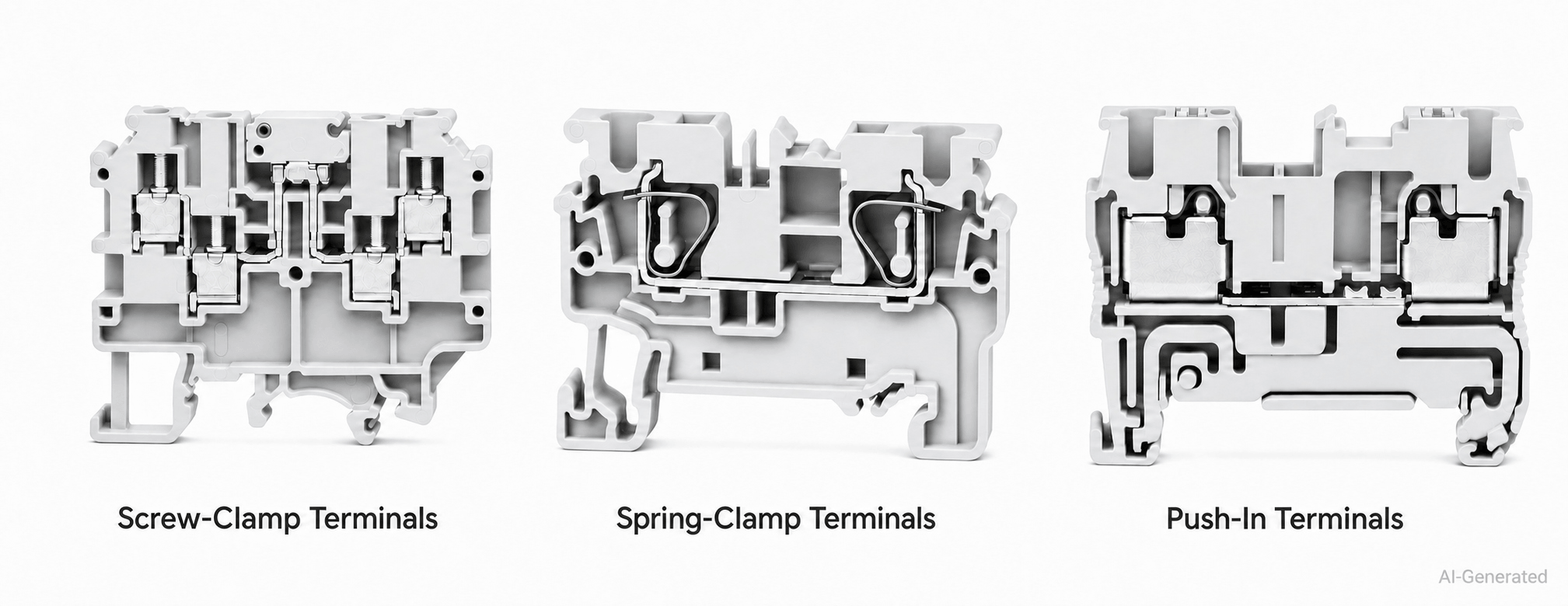
Screw-Clamp Terminals
Screw-clamp terminals use a screw-operated mechanism to secure the conductor.
They remain common across industrial equipment because the technology is familiar and available in a wide range of configurations.
When evaluating a screw-clamp design, look at:
- Supported wire range
- Conductor type
- Tightening torque
- Screw access
- Required tools
- Maintenance procedure
Torque is particularly important. Insufficient tightening can reduce connection reliability, while excessive torque can damage the conductor or terminal mechanism.
Spring-Clamp Terminals
Spring-clamp terminals maintain conductor pressure through a spring mechanism.
They are widely used in industrial automation and control systems where consistent clamping force and efficient wiring are important.
The exact design matters, however. Check the supported conductor types and the insertion and removal procedure rather than assuming that all spring terminals operate in the same way.
Push-In Terminals
Push-in terminals are designed for rapid conductor insertion and can reduce wiring time in applications with a large number of connections.
They are particularly useful in high-density control panels where installation efficiency is a major consideration.
Depending on the design, solid or ferruled conductors may be inserted directly, while a tool may be required for removal.
Check:
- Wire size
- Conductor construction
- Ferrule requirements
- Insertion method
- Release mechanism
- Tool requirements
5.Select the Mounting Configuration
A terminal can meet the electrical requirements and still fail the installation if it does not fit the available space.
DIN Rail Mounting
DIN rail terminals are widely used in industrial control cabinets, PLC systems, machine controls, and automation equipment.
When selecting a DIN rail terminal, confirm:
- Compatible rail profile
- Terminal width
- Mounting direction
- End stops
- End plates
- Partition plates
- Marking accessories
Terminal width deserves particular attention in high-density cabinets. A narrow terminal can save panel space, but only when its electrical spacing, conductor capacity, and service access remain suitable.
PCB Mounting
PCB terminals provide a direct interface between field wiring and a printed circuit board.
Key parameters include:
- Terminal pitch
- Number of positions
- Pin configuration
- PCB hole pattern
- Wire range
- Current rating
- Voltage rating
- Wire-entry orientation
- Overall height
For compact electronic equipment, the mechanical envelope can be just as restrictive as the electrical rating.
Panel Mounting
Panel-mounted terminals are used where the connection point must be secured directly to an enclosure or mounting surface.
Check:
- Mounting hole dimensions
- Panel thickness
- Mounting hardware
- Terminal orientation
- Wire access
- Clearance around the connection
Terminal Pitch and Terminal Width
Terminal pitch is the center-to-center distance between adjacent terminal positions. Terminal width is the physical width occupied by each terminal.Both affect the final assembly size.
For example, if each modular terminal occupies 5 mm of DIN-rail width, 20 terminals would occupy approximately:
20 × 5 mm = 100 mm
This calculation excludes additional space required for end plates, separators, end stops, and other accessories.
This simple calculation illustrates why terminal width can have a significant effect on cabinet layout.
A smaller pitch or narrower terminal can increase wiring density, but it should not compromise required creepage, clearance, conductor access, tool access, or heat dissipation.
Wire Entry and Service Access
Wire entry direction is easy to overlook during initial layout.
Depending on the terminal design, conductors may enter from the top, side, front, or another direction. This affects routing and the technician's ability to access the connection.
Make sure the finished assembly provides enough room to:
- Insert and remove conductors
- Operate screws or release mechanisms
- Read terminal markings
- Perform electrical testing
- Access adjacent connections
- Route and bend conductors safely
6.Evaluate the Operating Environment
The installation environment can affect a terminal block's electrical and mechanical performance. Before selecting a model, check the conditions at the actual installation point.
| Environmental Factor | What to Check | Selection Consideration |
| Temperature | Ambient temperature, temperature rise | Verify operating limits and current derating |
| Vibration | Continuous or intermittent vibration | Check connection retention and test data |
| Moisture | Humidity, condensation, water exposure | Consider insulation and corrosion resistance |
| Dust and chemicals | Dust, oil, solvents, corrosive agents | Check material and chemical compatibility |
| Flammability | Equipment fire-safety requirements | Verify housing material and applicable ratings |
Temperature and Current Derating
Ambient temperature affects the thermal margin of a loaded terminal. This is particularly relevant in enclosed control cabinets, high-current circuits, and densely packed assemblies.
For loads close to the rated current, check the manufacturer's temperature-rise data and derating information rather than using the nominal current rating alone.
Vibration and Mechanical Stress
For machinery, motors, transportation equipment, and other vibration-prone applications, check the terminal's connection retention and mechanical test data.
Spring-based connection systems can be suitable for some vibration-prone applications, but performance depends on the specific terminal design. Use the manufacturer's test data when making the final selection.
Moisture, Dust, and Chemicals
Moisture and contamination can affect conductive and insulating parts. Depending on the installation, check:
- Contact material and surface treatment
- Housing material
- Corrosion resistance
- Chemical compatibility
- Enclosure protection
The terminal should be evaluated together with the enclosure and wiring system, particularly where water, oil, solvents, or corrosive substances are present.
Insulation and Flammability
Where temperature or fire-safety requirements are more demanding, verify the housing's:
- Operating temperature
- Insulation properties
- Flammability rating
- Chemical resistance
Check these requirements against the applicable equipment standards and the manufacturer's documentation for the specific terminal block.
7.Verify Standards and Certifications
A terminal can satisfy the basic electrical and mechanical requirements and still be unsuitable for the finished equipment if the required approvals are missing.
Electrical Safety Requirements
Review the complete set of applicable requirements, including:
- Working voltage
- Rated current
- Insulation performance
- Creepage
- Clearance
- Temperature rise
- Protection against accidental contact
These characteristics should be considered together rather than evaluated independently.
Common Terminal Block Standards
The standards required for a terminal block depend on its design, application, and target market. Depending on the product and where it will be used, relevant standards may include IEC 60947-7-1, UL 1059, and CSA C22.2 No. 158.
Terminal blocks in the same category may have different ratings and certifications, so the product category alone is not enough to determine compliance. Check the documentation for the specific model you plan to use.
If the equipment will be sold in multiple markets, identify the applicable requirements for each market and confirm the terminal block's ratings and certifications in the manufacturer's datasheet or certification documents.
Flammability Requirements
Where fire performance is relevant, check the actual housing material specification and the product's documented flammability information.
A material name alone is not enough to establish compliance.
8.Consider Terminal Block Accessories
For DIN rail installations, the terminal block itself is only one part of the final assembly.
Common accessories include:
- End stops
- End plates
- Partition plates
- Marking tags
- Jumpers
- Test accessories
- Protective covers
These components can affect the stability, identification, spacing, and serviceability of the completed terminal assembly.
For example, end stops secure the terminal arrangement on the rail, while end plates and partition plates can provide the required separation between circuits or terminal groups.
Accessories should therefore be considered during the initial layout rather than added after the terminal selection has been finalized.
9.How to Read a Terminal Block Datasheet
A datasheet is the final check before approving a terminal block. Focus on the specifications that directly affect the application rather than comparing headline ratings alone.
| Category | Key Specifications | What to Confirm |
| Electrical | Rated voltage, current, temperature rise | Suitable for the actual load and operating conditions |
| Conductor | AWG / mm², conductor type, ferrule support | Compatible with the selected wire |
| Mechanical | Width, pitch, height, mounting | Fits the cabinet, PCB, or DIN rail layout |
| Environmental | Operating temperature, vibration, materials | Suitable for the installation environment |
| Compliance | Standards and certifications | Meets the requirements of the finished equipment |
For electrical ratings, check the conditions behind the published values, including conductor size, ambient temperature, and temperature-rise limits. For conductor compatibility, verify both the wire range and conductor construction. Mechanical dimensions should be checked against the actual panel or PCB layout, including wire-entry and tool-access space.
Finally, confirm the certifications for the specific model, not simply the product series. The manufacturer's datasheet and technical documentation should be the final reference for selection and compliance.
10.Practical Example: Selecting a Terminal Block for a PLC Control Panel
Consider a PLC control panel with 24 VDC, 2 A continuous current, 1.5 mm² stranded wire, DIN rail mounting, high wiring density, and frequent maintenance access.
The selection is relatively straightforward once the requirements are defined.
First, select a terminal with a suitable voltage and current rating under the actual operating conditions. The terminal must also accept 1.5 mm² stranded conductors and the ferrules used in the panel, if applicable.
For a high-density panel with frequent access, a push-in or spring-clamp terminal may be preferable because it can simplify wiring and maintenance. A screw-clamp design remains suitable when screw termination fits the installation and service procedure.
Next, verify the DIN rail profile, terminal width, and required accessories such as end stops, end plates, markers, and jumpers. Make sure there is enough room for conductor routing and tool access.
For this indoor application, also check the operating temperature and any relevant contamination or vibration requirements.
The final datasheet review should cover:
Voltage → Current → Wire Size → Connection Method → Mounting → Dimensions → Environment → Certifications
This approach avoids selecting a terminal based on a single specification and ensures that the complete terminal assembly fits the electrical, mechanical, and maintenance requirements of the panel.
11.Common Terminal Block Selection Mistakes
Most selection errors come from checking one parameter while overlooking the rest.
| Common Mistake | Better Approach |
| Selecting by current rating alone | Check conductor, temperature, arrangement, and test conditions |
| Choosing by maximum wire size | Check the complete AWG/mm² range and conductor type |
| Ignoring rating conditions | Review the conditions behind voltage and current ratings |
| Choosing connection type by speed | Consider wire type, vibration, maintenance, and tools |
| Overlooking the environment | Check temperature, moisture, dust, chemicals, and vibration |
| Ignoring mechanical fit | Verify width, pitch, height, mounting, and wire routing |
| Checking certification too late | Confirm required approvals before finalizing the part |
Key Takeaway
A terminal block should be selected as part of the complete wiring system.
The right choice is the one that satisfies the circuit's electrical requirements, accepts the specified conductor, fits the equipment, suits the installation environment, and meets the required compliance standards.
FAQs
How do I choose a terminal block for my wire size?
Match the wire to the manufacturer's AWG or mm² range and confirm whether the terminal supports solid, stranded, or fine-stranded conductors. If using a ferrule, verify its compatibility with the terminal.
Which is better: screw-clamp, spring-clamp, or push-in?
There is no universal best option. Screw-clamp terminals suit conventional termination, while spring-clamp and push-in designs can simplify high-volume wiring. The conductor type, maintenance method, vibration, and installation requirements should guide the choice.
How do I wire a terminal block?
First verify the terminal's wire range and connection method. Prepare the conductor according to the manufacturer's instructions, insert it fully into the terminal, and apply the specified tightening torque where required. For spring and push-in terminals, follow the specified insertion and release procedure.
Are DIN rail terminal blocks suitable for industrial applications?
Yes. DIN rail terminal blocks are widely used in PLC panels, machine controls, industrial automation, instrumentation, and power distribution. Selection depends on electrical ratings, wire size, rail compatibility, terminal dimensions, environmental conditions, and certifications.
Conclusion
Selecting the right terminal block starts with the application, not the catalog. Define the electrical, conductor, mechanical, environmental, and compliance requirements before comparing connection methods and product specifications.
The best choice is not necessarily the one with the highest rating, but the one that provides a reliable connection, fits the equipment, supports maintenance, and meets the requirements of the complete system.
A structured selection process helps engineers avoid compatibility issues and choose a terminal block that performs reliably throughout the equipment's service life.
Keep Learning
A Complete Guide to DIN Rail Terminal Blocks
Introduction In a control cabinet, field wiring from sensors, switches, valves, and other equipment must be connected to PLC I/O, power supplies, relays, and protection devices. Without a defined termination point, wiring becomes harder to trace, test, and maintain. DIN rail terminal blocks provide a structured interface between field wiring and internal cabinet circuits. Depending on the application, a terminal strip may include feed-through, PE, disconnect, fuse, distribution, or multi-level termina......
How to Choose Between Screw, Spring, and Push-In Terminal Blocks
Introduction The connection method is more than a choice between a screw, a spring, or a push-in mechanism. It determines how clamping force is generated, how the conductor is retained, how the connection responds to vibration and temperature changes, and how much time is required for installation and maintenance. Screw-clamp, spring-clamp, and push-in terminal blocks can all provide reliable electrical connections when correctly specified. The difference is how each design achieves that connection an......
How to Select a Terminal Block: A Complete Selection Guide
Introduction Choosing the right terminal block requires more than matching voltage and current ratings. Terminal block selection also depends on wire size, conductor type, connection method, mounting configuration, available space, operating environment, and safety requirements. In control panels and industrial equipment, the terminal block must provide a reliable electrical connection while supporting efficient wiring, testing, and maintenance. A practical selection sequence is: Application → Voltage......
What Is a Terminal Block? Types, Working Principles, and Applications
Introduction A terminal block is a modular electrical connector used to securely connect and organize multiple wires in electrical systems. It provides a reliable connection point for power distribution, signal transmission, and circuit management. Commonly used in industrial automation, control panels, and electrical equipment, terminal blocks help improve wiring organization, simplify maintenance, and enhance system reliability. In this guide, you will learn what a terminal block is, how it works, t......
5 Common Pressure Sensor Problems and How to Troubleshoot Them
Introduction: In previous articles, we explored “What Is a Pressure Sensor?”, “Pressure Sensors Explained: Working Principles, Types, and Applications,” and “How to Select the Right Pressure Sensor,” covering the fundamentals of pressure sensors, including their working principles, types, applications, and key selection considerations. However, even a properly selected pressure sensor may encounter performance issues during operation due to factors such as wiring errors, improper installation, harsh e......
How to Select the Right Pressure Sensor?
Introduction: In previous articles, we explored “What Is a Pressure Sensor?” and “Pressure Sensors Explained: Working Principles, Types, and Applications,” covering the fundamentals of pressure sensors, including how they work, different sensor types, and their applications across industrial automation systems. However, understanding how pressure sensors work is only the first step. In real industrial applications, selecting the right pressure sensor requires engineers to consider multiple factors, in......