Different-Wire Stepper Motors Wiring & Diagrams Explained
19 min
- What Does the Number of Wires on a Stepper Motor Mean?
- 4, 5, 6, and 8 Wire Stepper Motors Compared
- Stepper Motor Wiring Diagrams by Wire Count
- How to Identify the Wires and Windings of an Unknown Stepper Motor
- How to Choose a Driver for a Stepper Motor
- Advantages, Limitations, and Applications of Different Wire Stepper Motors
- How to Connect a Stepper Motor?
- Frequently Asked Questions
- Conclusion
The number of wires coming from a stepper motor tells you how many winding terminals are accessible in the motor, but it does not, by itself, determine the motor type or how the motor should be driven. The internal winding configuration determines which wiring methods are possible, including bipolar, unipolar, series, and parallel connections.
This guide explains how a 4 wire stepper motor, 5 wire stepper motor, 6 wire stepper motor, and 8 wire stepper motor are configured, how to identify their windings, and how their different wiring options affect driver selection and motor performance. You will also learn how to identify an unknown stepper motor, understand its stepper motor wire connections, and connect it safely.
What Does the Number of Wires on a Stepper Motor Mean?
The number of wires coming from a stepper motor indicates how many leads, or winding terminals, are brought out of the motor winding. It does not directly tell you how many windings or coils exist inside the motor. The external stepper motor wires simply provide access to selected points on those internal windings.
For example, a typical 4 wire stepper motor provides two complete winding pairs, while a typical 6 wire stepper motor provides access to the ends and center tap of each phase winding. An 8 wire stepper motor provides access to individual half-windings, giving you more ways to connect the motor. Therefore, wire count should be treated as the starting point for understanding the motor's winding configuration.
Wire Count vs. Winding Configuration
A stepper motor winding consists of coils of wire that generate magnetic fields when energized. The winding configuration describes how these coils or winding sections are arranged and connected. The external leads and wire provide access to selected points in the windings, allowing the driver to control the current through them.
The way these winding leads are brought outside the motor determines the available wiring methods. A 4 wire stepper motor normally provides two complete winding pairs for bipolar operation. A 6 wire stepper motor commonly provides two center-tapped windings, while an 8 wire stepper motor provides separate access to four half-windings. Understanding this relationship is important because the winding configuration determines how the motor can be connected and what type of driver it requires.
4, 5, 6, and 8 Wire Stepper Motors Compared
The difference between a 4 wire stepper motor, 5 wire stepper motor, 6 wire stepper motor, and 8 wire stepper motor is mainly the amount of access provided to the internal windings. More stepper motor wires generally provide more connection options, but more wires do not automatically mean that one motor will perform better than another.
4 Wire Stepper Motor
A 4 wire stepper motor typically has two complete phase windings, with both ends of each winding brought outside the motor. Because there are no externally accessible center taps, the motor is normally connected to a bipolar stepper driver that can reverse current through each winding phase.
The main advantage of a 4 wire stepper motor is its simple connection. Each pair of wires belongs to one phase, so once the two winding pairs have been identified, the motor can be connected directly to the corresponding phase outputs of a bipolar driver.
5 Wire Stepper Motor
A 5 wire stepper motor in a typical two-phase configuration contains two center-tapped phase windings whose center taps are connected together inside the motor. This arrangement produces five external stepper motor wires: two ends for each winding and one shared common connection.
The shared center connection makes this configuration commonly suited to unipolar operation, where the driver switches current through different halves of each winding. Because the two center taps are permanently connected internally, a typical two-phase, 5 wire stepper motor does not provide the same independent winding access as a 6 wire stepper motor, whose center taps are brought out separately. However, the internal winding arrangement can vary in motors with different phase counts or specialized designs, so the manufacturer's wiring diagram should be checked before selecting a connection method.
6 Wire Stepper Motor
A 6 wire stepper motor commonly contains two center-tapped phase windings, but each center tap is brought outside the motor as a separate wire. This gives you access to both halves of each winding as well as the complete winding.
Depending on the motor's specifications and the driver being used, the motor can be connected for unipolar operation or for bipolar full-coil operation. When a 6-wire stepper motor is connected in a bipolar full-winding configuration, the center taps must be left unconnected and properly insulated. This configuration uses the entire phase winding, so its resistance and inductance differ from those in half-winding operation. Before powering on the motor, always verify the manufacturer's rated current and recommended driver current settings for the selected wiring configuration.
8 Wire Stepper Motor
An 8 wire stepper motor provides separate access to four half-windings. This gives you greater control over how the internal windings are connected to the driver.
Depending on the motor design, the half-windings can commonly be connected in series or parallel.
For an 8-wire stepper motor, the four half-windings can often be connected in series or parallel, provided the manufacturer supports these configurations. Series connection typically increases phase resistance and inductance, while parallel connection typically lowers the equivalent phase resistance and inductance and requires a higher phase-current capability from the driver. The suitable arrangement depends on the motor's specifications, supply voltage, target speed, and torque requirements. Correct winding polarity is essential. Therefore the manufacturer's specifications should be checked before selecting either arrangement.
Stepper Motor Wiring Diagrams by Wire Count
Stepper motor wire colors are not universal, the diagram below should be understood as a representation of the winding arrangement rather than a universal color code. Always use the manufacturer's wiring diagram when it is available.
4 Wire Stepper Motor Wiring Diagram
A typical 4 wire stepper motor wiring diagram consists of two independent winding with 2 external wire from each winding:
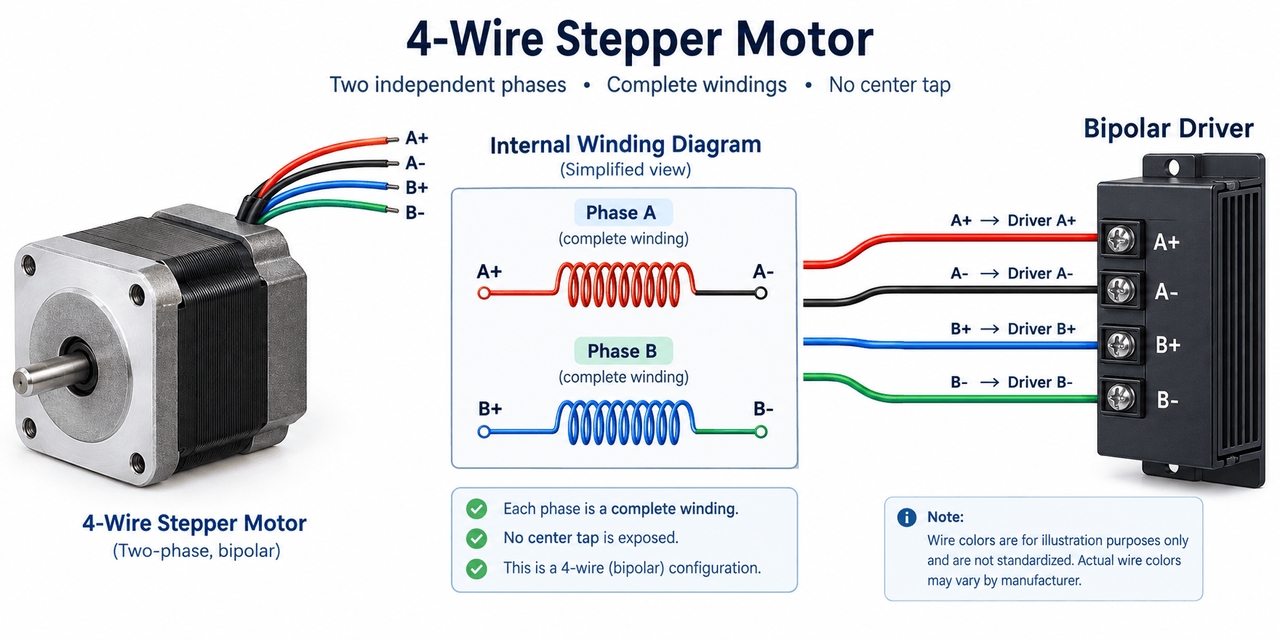
Each complete winding connects to one phase of a bipolar driver. If the motor needs to rotate in the opposite direction, the polarity of one phase can be reversed by swapping the two wires belonging to that phase.
5 Wire Stepper Motor Wiring Diagram
A typical two-phase, 5 wire stepper motor contains two center-tapped windings with a shared internal center connection:
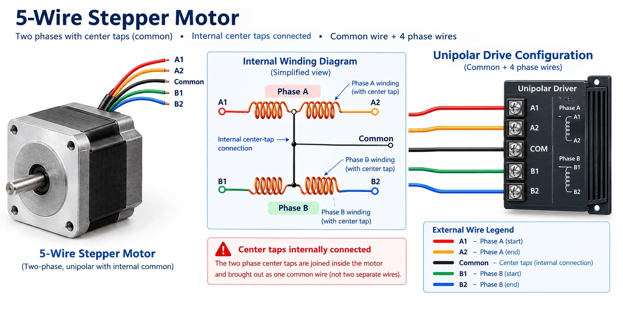
The common connection is used as the shared supply connection in a typical unipolar arrangement, while the outer winding leads are switched by the driver in a specific sequence to make the motor step..
6 Wire Stepper Motor Wiring Diagram
A typical 6 wire stepper motor wiring diagram can be represented as:
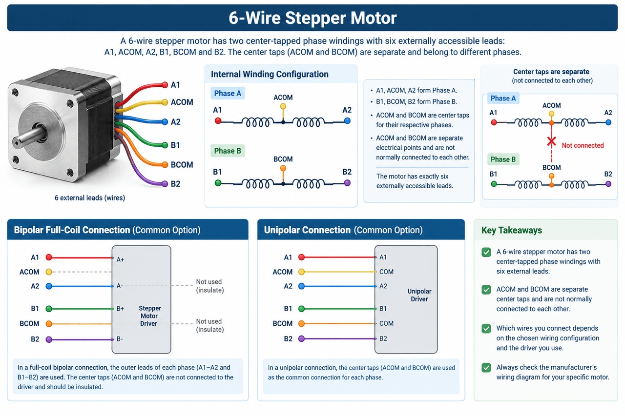
For unipolar operation, the center taps are used as common connections. For bipolar full-coil operation, the center taps are left disconnected and the two outer ends of each complete winding are connected to the driver. The correct connection depends on the motor and driver specifications.
8 Wire Stepper Motor Wiring Diagram
A typical 8 wire stepper motor wiring diagram provides four separately accessible half-windings:
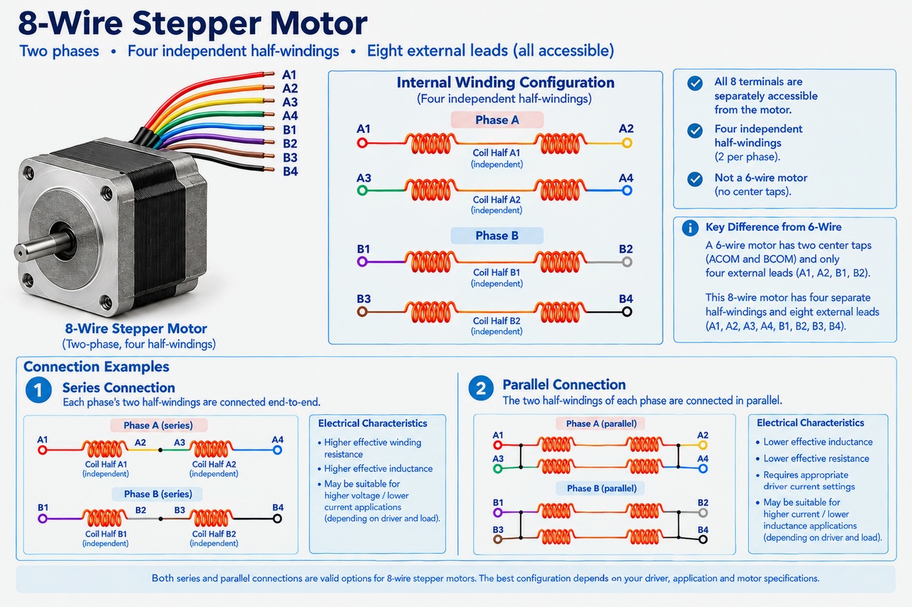
These half-windings can be connected in series or parallel when supported by the motor. Because the correct winding pairing and polarity are important, follow the manufacturer's wiring diagram rather than assuming a particular stepper wire color or connection.
Bipolar vs. Unipolar Stepper Motor Operation
Bipolar and unipolar operation describe how the driver energizes the motor windings, not simply how many wires the motor has. In bipolar operation, the driver reverses the current direction through each phase winding, allowing the same winding to produce magnetic fields in opposite directions. This requires a driver capable of controlling current in both directions, such as an H-bridge or bipolar stepper driver.
In unipolar operation, the current flows through one half of a center-tapped winding at a time. The center tap provides a common connection, while the driver switches the other winding terminals to energize different coil sections. This arrangement can simplify the driver circuit, but it does not use the entire winding in the same way as a full-coil bipolar connection.
The distinction becomes important when choosing a driver. A typical 4-wire stepper motor exposes two complete phase windings and is commonly used with a bipolar driver. A typical 5-wire stepper motor has two center-tapped phases whose center taps are internally connected, making it commonly associated with unipolar operation. A 6-wire stepper motor provides separate center taps, giving it more possible connection methods, while an 8-wire stepper motor provides four separately accessible half-windings that can be arranged in different configurations when supported by the motor and driver.
Therefore, do not determine bipolar or unipolar operation from wire count alone. First identify the motor's winding structure, then determine which connection methods the manufacturer supports, and finally choose a driver that matches the selected configuration.
How to Identify the Wires and Windings of an Unknown Stepper Motor
If you have an unknown stepper motor without a wiring diagram, you can begin identifying its winding structure by counting the stepper motor wires and measuring the resistance between them. The purpose of this process is to determine which wires are electrically connected through a winding and how the winding terminals are arranged.
Disconnect the motor completely from any driver or power supply before testing it. Label the wires and use a multimeter in resistance mode. A finite resistance reading indicates an electrical path between the tested wires, while an open-circuit reading generally indicates that no direct electrical path exists between them. However, resistance measurements are only a preliminary identification method. The pattern of readings can help you identify winding pairs and possible internal connections, but the interpretation depends on the motor's wire configuration. Probe contact quality and measurement errors at very low resistance values can also affect the readings. For unfamiliar or specialized motors, confirm the winding arrangement using the manufacturer's wiring diagram whenever possible.
For a typical 4-wire stepper motor, the two wires of each phase form one isolated winding pair.
For example, if the wires are numbered 1–2–3–4:
- Wires 1–2: finite resistance, indicating one winding pair (Phase A).
- Wires 3–4: finite resistance, indicating the other winding pair (Phase B).
- Wires 1–3, 1–4, 2–3, and 2–4: open circuit, because the two phase windings are electrically isolated from each other.
- For a typical 5-wire stepper motor, the internally connected common point can produce finite resistance readings between multiple wire combinations. Therefore, a finite resistance reading alone does not necessarily mean that two wires belong to the same isolated winding. Compare the resistance readings across different wire combinations to help identify the shared common connection, and consult the manufacturer's wiring diagram if the results are unclear.
- For a 6-wire stepper motor, the center tap can usually be identified because its resistance to either end is approximately half the end-to-end resistance of the same winding, provided the two winding halves have similar resistance. Measure the resistance between the three wires in each phase group to help identify the center tap and the two winding ends.
- For an 8-wire stepper motor, resistance measurements can help identify the four individual half-windings. Each half-winding forms a pair of wires with finite resistance between them.
- However, identifying these half-windings is only the first step. You must also determine which half-windings belong to the same phase and verify their polarity before connecting them in series or parallel. Resistance measurements alone do not always establish the correct phase pairing and polarity. Confirm these details using the manufacturer's wiring diagram before connecting the motor in series or parallel.
Count the Wires First
The first step in identifying an unknown stepper motor is to count and label all of the wires coming from the motor. A typical 4 wire stepper motor has two winding pairs, a typical 5 wire stepper motor has internally connected center taps, a typical 6 wire stepper motor has separately accessible center taps, and an 8 wire stepper motor has separately accessible half-windings.
Do not use wire color as your primary identification method because stepper wire colors vary between manufacturers. Instead, label the wires as 1, 2, 3, and so on, then use resistance measurements to determine their relationships.
Use a Multimeter to Find the Windings
Set the multimeter to resistance (Ω) and measure between the labeled stepper motor wires. Record the readings rather than relying only on the continuity buzzer, because the actual resistance values help reveal the winding structure.
For a typical 4 wire stepper motor, two pairs should show finite or low resistance while measurements between different phases should normally show an open circuit or high resistance. For a typical 6-wire stepper motor with approximately symmetrical center-tapped windings, the resistance from the center tap to either end is approximately half the end-to-end resistance of the same phase. Small deviations may occur because of winding tolerances and measurement limitations.
With an 8 wire stepper motor, resistance measurements can identify the individual half-winding pairs, although determining which pairs form each phase may require the manufacturer's pinout.
Resistance testing helps identify the winding structure, but the motor's rated current, resistance, inductance, and approved wiring configurations should still be checked before applying power.
How to Choose a Driver for a Stepper Motor
Choosing a stepper motor driver starts with identifying the motor's winding configuration and deciding how those windings will be connected. The driver must support that connection and provide the required phase current within its specified operating range.
Do not assume that the voltage printed on the motor is automatically the voltage that should be supplied to the driver. A stepper motor's rated winding voltage is generally related to its rated phase current and winding resistance. A current-regulated driver may use a supply voltage higher than the motor's rated winding voltage to improve current rise at higher speeds, but only within the driver's specified supply-voltage range and the motor's electrical and thermal limits. The phase-current limit must be set according to the motor manufacturer's instructions and the selected winding configuration.
Using a suitable higher supply voltage can help the winding current rise faster, improving high-speed performance when the motor and driver are operated within their specifications.
Check These Parameters Before Choosing a Driver
Before choosing a driver, check the motor's winding configuration, rated phase current, resistance, inductance, required speed, and torque requirements. The driver's current range and supply-voltage range must be suitable for the selected motor connection.
Also consider microstepping, control interface, thermal requirements, and protection features. If an 8 wire stepper motor is connected in parallel instead of series, for example, its electrical requirements change, so the driver must be capable of supplying the resulting current.
Advantages, Limitations, and Applications of Different Wire Stepper Motors
A 4 wire stepper motor provides a simple, fixed winding connection and is commonly used with bipolar drivers. A 5 wire stepper motor is commonly used with unipolar drive arrangements, but its internally connected center taps limit its wiring flexibility.
A 6 wire stepper motor provides separate center taps, allowing different connection methods when supported by the manufacturer. An 8 wire stepper motor provides the greatest flexibility because its half-windings can be connected in series or parallel. These configurations can be used to change characteristics such as current demand and inductance to suit the application.
| Wire Counts | Typical connection options | Main advantage | Main limitation |
| 4-wire stepper motor | Bipolar operation using two complete phase windings | Simple, straightforward wiring | The winding arrangement offers fewer connection options |
| 5-wire stepper motor | Commonly suited to unipolar operation | Shared internal common connection supports typical unipolar arrangements | Internal center taps limit independent winding access |
| 6-wire stepper motor | Unipolar or bipolar full-winding operation, when supported | Separate center taps provide more connection flexibility | Current settings and electrical characteristics must be checked for the selected configuration |
| 8-wire stepper motor | Series or parallel connections, when supported | Greater flexibility in configuring the winding sections | Requires correct phase pairing and polarity, plus a driver capable of handling the selected connection |
Technical note: These descriptions refer to typical and most common motor configurations. The manufacturer's specifications determine which connection methods are supported.
Therefore, there is no universally better stepper motor wire configuration. The appropriate motor depends on the required speed, torque, driver capability, winding characteristics, and available connection methods.
How to Connect a Stepper Motor?
Connecting a stepper motor correctly involves identifying the motor, determining its winding configuration, selecting the appropriate connection, and matching it to a suitable driver.
Step 1: Find the Motor Label or Model
Start by checking the motor label for the manufacturer, model number, rated current, resistance, and other electrical specifications. If the model number is available, find the manufacturer's wiring diagram before testing the stepper motor wires.
Step 2: Count the Wires
Count and label the wires coming from the motor. Make sure you distinguish winding wires from other connections such as protective ground or encoder wires. Do not assume that the wire colors follow a universal standard.
Step 3: Identify the Windings
If the wiring is unknown, use a multimeter to measure resistance between the labeled wires. Use the resistance readings to identify winding pairs, center taps, or half-windings.
Step 4: Find the Manufacturer's Wiring Diagram
Find the wiring diagram for the exact motor model whenever possible. The manufacturer's diagram will show which wires belong to each phase and which configurations the motor supports.
Step 5: Match the Motor to the Driver
Confirm that the driver supports the selected winding configuration and can supply the required phase current. Set the driver's current according to the motor's specifications and make sure the driver's supply voltage remains within its rated range.
Step 6: Power Up Carefully
Before applying power, check every connection and properly insulate unused center-tap or winding wires. Never connect or disconnect stepper motor wires while the driver is powered, because this can damage the driver.
Start the motor at a low speed and check its movement. If it does not behave as expected, recheck the winding identification, phase connections, driver current, control signals, and mechanical load instead of randomly changing wires.
Frequently Asked Questions
How To Run 4 Wire Stepper Motor Without a Driver
A typical 4 wire stepper motor cannot simply be connected to a DC power supply and expected to rotate continuously. The current through its two windings must be switched in the correct sequence and direction, which is normally handled by a bipolar stepper motor driver.
Building the required switching circuit yourself is possible with suitable H-bridge circuitry and a controller, but that circuit is effectively functioning as a stepper motor driver.
Does the Number of Wires Determine Whether a Stepper Motor Is Bipolar or Unipolar?
No. The number of wires tells you how the winding terminals are brought outside the motor, while the winding arrangement determines which connection methods are possible.
A typical 4 wire stepper motor provides two complete windings, a 5 wire stepper motor commonly has internally connected center taps, a 6 wire stepper motor provides separate center taps, and an 8 wire stepper motor provides separate half-windings.
Is an 8 Wire Stepper Motor Better Than a 4 Wire Motor?
An 8 wire stepper motor is not automatically better than a 4 wire stepper motor. Its main advantage is that its separate half-windings provide more configuration options, allowing you to select series or parallel connections when supported.
A 4 wire stepper motor is simpler when its fixed winding arrangement already provides the performance required by the application. The better choice depends on the motor specifications and application rather than wire count alone.
Can I Connect a 6 Wire Stepper Motor as a 4 Wire Motor?
Yes, a typical 6 wire stepper motor to 4 wire connection is possible when the motor supports bipolar full-coil operation. In this arrangement, the two center-tap wires are left disconnected and insulated, while the two outer ends of each complete phase winding are connected to the bipolar driver.
However, the motor's electrical characteristics and current requirements change with the connection. Always check the manufacturer's specifications before using a 6 wire stepper motor to 4 wire configuration.
How Do I Identify a Stepper Motor With No Wiring Diagram?
To identify an unknown stepper motor, first count and label the stepper motor wires, then use a multimeter in resistance mode to find which wires belong to the same winding.
The resistance pattern can reveal winding pairs and center taps. For an 8 wire stepper motor, the individual half-windings can be identified this way, but determining the correct phase pairing may require the manufacturer's pinout.
What Wire Gauge Should I Use for a Stepper Motor?
The correct stepper motor wire gauge depends on the motor's operating current, cable length, allowable voltage drop, temperature, and installation conditions. There is therefore no single wire gauge that is correct for every stepper motor.
For an existing motor cable, follow the manufacturer's recommended cable size. When replacing or extending the cable, choose a conductor size that can safely carry the motor's operating current while keeping voltage drop and heat within acceptable limits.
Conclusion
Understanding a stepper motor wire count is really about understanding how the internal windings are configured and brought outside the motor. A 4 wire stepper motor normally provides two complete windings, a 5 wire stepper motor commonly has internally connected center taps, a 6 wire stepper motor provides separate center taps, and an 8 wire stepper motor provides separate half-windings.
Once you understand the relationship between stepper motor wires, winding configuration, connection method, and driver requirements, the different wire counts become much easier to understand. When connecting an unknown motor, identify the windings, verify the manufacturer's specifications, select the appropriate driver, and check every connection before applying power.
Keep Learning
Different-Wire Stepper Motors Wiring & Diagrams Explained
The number of wires coming from a stepper motor tells you how many winding terminals are accessible in the motor, but it does not, by itself, determine the motor type or how the motor should be driven. The internal winding configuration determines which wiring methods are possible, including bipolar, unipolar, series, and parallel connections. This guide explains how a 4 wire stepper motor, 5 wire stepper motor, 6 wire stepper motor, and 8 wire stepper motor are configured, how to identify their windi......
How to Choose a Shaft Coupling: Rigid vs Beam vs Jaw vs Universal Joint
Key Takeaways Shaft Coupling Basics: A shaft coupling transmits torque between driving and driven shafts while accommodating misalignment, vibration, and thermal expansion. The core choice is between rigid (zero flexibility, maximum torque density) and flexible (misalignment-tolerant, vibration-damping) designs. Four Primary Types: Rigid couplings offer zero backlash but require perfect alignment; helical beam couplings provide precision motion for light-duty drives; jaw couplings deliver versatile vi......
Roller Chain Size Chart: ANSI and BS Sizes in mm and Inches
Key Takeaways Identify the chain series first: ANSI and BS-series size codes belong to different dimensional families; changing the units does not change the chain type. Check four details together: Pitch, roller diameter, inner width and number of rows. Matching pitch alone is not enough to choose a replacement. Use the millimeter columns for comparison: Inch equivalents appear beside them, so there is no need to interpret two units in one cell. Count the gaps when measuring pitch: Six consecutive pi......
How to Choose Between Closed-Loop and Open-Loop Stepper Motors
People need the right motor for machine projects. Picking between a closed-loop and open-loop stepper motor shapes machine accuracy and total cost. You can build simple 3D printers with open-loop drives. You can run fast industrial equipment with closed-loop systems. This guide helps you pick the correct motor for your build. Key Takeaways Open-loop stepper systems operate without position feedback, while closed-loop systems use an encoder to monitor actual shaft position. Open-loop systems cannot det......
What Are Pillow Block Bearings? Definition, Working Principle & Applications
Key Takeaways A pillow block bearing is a self-contained bearing unit that combines a rolling-element bearing insert with a rigid housing, designed for shaft support on a flat mounting surface with the shaft axis parallel to the mounting plane. The housing provides structural alignment and load distribution, while the bearing insert handles radial and limited axial loads. Common locking mechanisms include set screws, eccentric collars, and adapter sleeves; each suits different shaft tolerances, vibrat......
Main Types of Servo Motors: AC, DC, and Everything in Between
1. Introduction By leveraging closed-loop feedback to precisely control position, velocity, and torque, servo motors serve as the backbone of modern automation. Yet, application success hinges on matching the right architecture to your load requirements—a task made challenging by the sheer variety of servo motor types available today. In this article, we map motor technology to application requirements through a practical taxonomy covering electrical topology, mechanical construction, performance spec......