What Is the Voltage of a NEMA 17 Stepper Motor?
12 min
- Key Takeaways:
- What Is The NEMA 17 Stepper Motor Voltage?
- Coil Voltage vs. Driver Supply Voltage: Understanding the Difference
- What Power Supply Voltage Does a NEMA 17 Stepper Motor Need?
- How to Calculate NEMA 17 Stepper Motor Voltage
- How to Choose the Right Voltage for a NEMA 17 Stepper Motor
- What Happens If the Voltage Is Too High or Too Low?
- Frequently Asked Questions about NEMA 17 Stepper Motor Voltage
- Conclusion
When designing or building precision electronics projects, understanding power requirements is critical for optimal performance. Choosing the correct NEMA 17 stepper motor voltage can often feel confusing given all the terminology and standards one must consider when choosing a NEMA 17 stepper motor. To help you navigate winding specifications, driver limits, and performance trade-offs, keep the following core concepts in mind before diving into our detailed guide.
Key Takeaways:
- NEMA 17 refers to a motor frame size standard, not a specific voltage rating.
- A NEMA 17 stepper motor voltage is not universal.
- Coil-rated voltage and driver supply voltage are different specifications and should not be confused.
- Both 12V and 24V can work for NEMA 17 motors, depending on the motor, driver, and application requirements.
- Proper selection requires evaluating motor current, winding resistance, inductance, driver limits, target speed, load, and thermal conditions.
What Is The NEMA 17 Stepper Motor Voltage?
What Does NEMA 17 Actually Mean?
NEMA 17 is a common designation for sizes of stepper motors defined by the American National Electrical Manufacturers Association, where the "17" in NEMA 17 refers to a nominal mounting face of 1.7 inches (43.2mm). Motors made to the standard of NEMA 17 in metric sizing typically have a square faceplate close to 42 mm x 42 mm with four mounting holes arranged in a 31mm x 31mm square. However, when purchasing NEMA 17 motors, always make sure to consult the manufacturer's datasheet for exact measurements and tolerances required for a specific motor, as measurements may vary slightly between different manufacturers or models.
Why Do NEMA 17 Motors Not Have One Standard Voltage?
Given the designation NEMA 17 refers to the common 1.7 inch x 1.7 inch package for stepper motors, a NEMA 17 motor does not have a common NEMA 17 voltage and instead the electrical parameters for each NEMA 17 motor is defined by the manufacturer based on design of the manufacturer.
Understanding the Specifications in a Motor Datasheet
NEMA 17 stepper motors typically come with a datasheet with important information required for operation; these values are important for determining what electrical parameters are suitable for the stepper motor. Examples of these electrical parameters will be discussed below:
| Key Parameter | Definition |
| Phase Current | Amount of electrical current that passes through each winding of a stepper motor. |
| Phase Resistance | Electrical resistance across one winding of a stepper motor |
| Winding Inductance | Electrical inductance of one winding of a stepper motor. |
| Holding Torque | Amount of static torque that can be resisted by a stepper motor while maintaining its position with power applied at a standstill at a specific phase current. |
| Step Angle | How much the stepper motor rotates per step, in degrees of rotation. |
Typical Examples of NEMA 17 Specifications
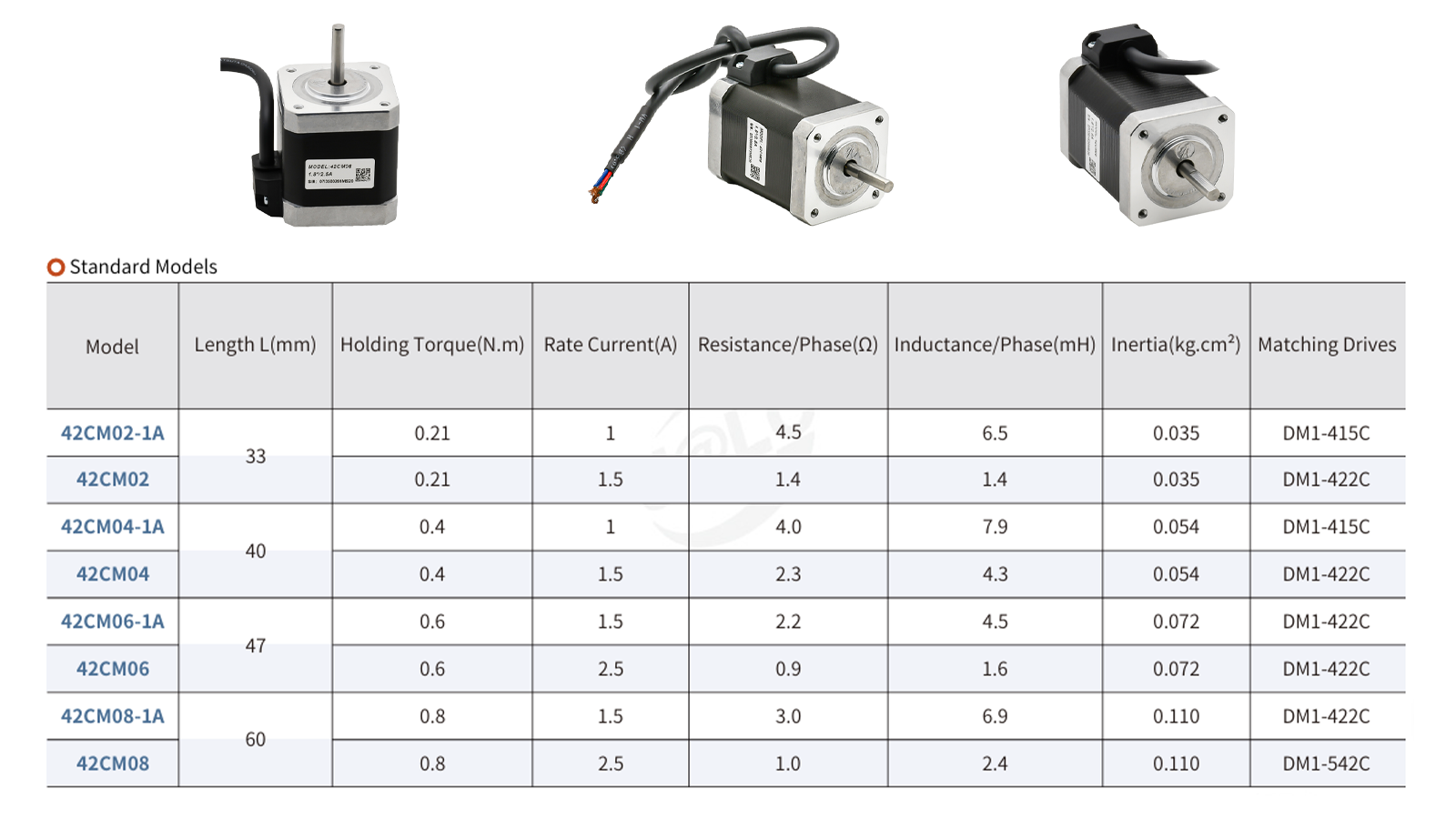
The table below shows an example of the specifications for a CM-series NEMA 17 open-loop stepper motor available from JLCMC.
Where to Find Voltage and Winding Information
Because winding information isn't consistently located, and electrical specifications vary by manufacturer, it's typically presented in a table with specifications such as Rated Current, Inductance per Phase, and Resistance per Phase.
Typically, NEMA 17 stepper motors are driven by a constant-current motor driver; therefore, the power supply voltage is dictated by the motor driver used.
Coil Voltage vs. Driver Supply Voltage: Understanding the Difference
What Is Coil Rated Voltage?
Coil voltage is the potential difference between the start and end of one winding of a stepper motor, derived from the stepper motor phase current and phase resistance.
Why Driver Supply Voltage Can Be Much Higher
Typically, stepper motor drivers use a supply voltage higher than the motor's rated winding voltage by utilizing PWM current regulation to control the current flowing through motor windings. The higher supply voltage helps overcome winding resistance and inductance, allowing the current to rise more quickly toward the configured current limit. This helps better maintain torque at higher operating speeds.
How Current Limiting Protects the Motor
Due to the fact that stepper motors are rated up to a particular phase current, connecting an unlimited power supply to the stepper motor would cause damage to the motor. If the calculated coil rated voltage is exceeded, this will cause the motor to draw more current than it is rated for and potentially burn out the motor.
Common Misunderstanding: Rated Voltage Is Not Power Supply Voltage
The calculated winding voltage is a resistive estimate based on winding resistance and rated current. It is not the recommended power supply voltage for the motor driver.
What Power Supply Voltage Does a NEMA 17 Stepper Motor Need?
Can You Use a 12V Power Supply?
A 12 V power supply can be used with a NEMA 17 stepper motor if the selected driver supports a 12 V input and can provide the required phase current. However, a lower supply voltage may limit the motor's ability to maintain torque at higher speeds, depending on its winding inductance and operating conditions. Among the stepper motor drivers currently available on JLCMC, a CL2C-series integrated closed-loop stepper drive has the lowest minimum operating voltage, at 20 V, which is still much higher than 12 V.
Can You Use a 24V Power Supply?
A NEMA 17 stepper motor can be used with a 24 V power supply if paired with a properly rated motor driver. In fact, 24 V is a common supply voltage for NEMA 17 applications, and many stepper motor drivers, such as a DM1-C series stepper motor driver, have a minimum power supply voltage of 24 V. In addition, power supplies designed specifically for stepper motor applications are widely available in 24 V and higher output options to meet the voltage requirements of different motor drivers. One such example of a 24V power supply is the JLCMC 24-60V 400W stepper and servo motor power supply.
How Supply Voltage Affects Speed and Torque
Due to the fact that stepper motors have phase inductance, the winding current within the motor does not instantly reach the target value and instead ramps up according to winding inductance. Therefore, if the voltage supplied to the motor driver is too low, then the motor might only be able to reach a fraction of the full phase current before the next step arrives. Using a higher voltage to the motor driver will allow for the phase current to be reached sooner, allowing for more torque from the stepper motor at high speeds.
Check the Driver's Voltage and Current Limits First
It is important to note that while a higher voltage allows the motor to reach its maximum phase current more quickly during each step, the supplied voltage must remain within the driver's rated limits to prevent damage. For example, the datasheet for a CL2C-series integrated closed-loop stepper drive specifies a maximum power supply voltage of 80 VDC and a maximum output current of 8 A.
12V vs. 24V Comparison
While at lower speeds, both 12V and 24V supplied as NEMA 17 stepper motor voltage will provide a similar level of torque, the performance of both sources diverges as speeds increase due to the fact that this means the time taken per step decreases, meaning that the lower voltage source would be less able to overcome the phase inductance within the stepper motor, meaning that with each step the lower voltage source would actually provide less current than the higher voltage source.
How to Calculate NEMA 17 Stepper Motor Voltage
Step 1: Calculate Coil Voltage from Current and Resistance
Coil Voltage is defined as:
V = I × R
Where:
V = Coil Voltage
I = Phase Current
R = Phase Resistance
So, for example, with a phase resistance of 2 Ohms and a rated phase current of 1.5A, the coil voltage calculated would be
2Ω × 1.5A = 3V
Step 2: Select a Compatible Driver Supply Voltage
Once a coil voltage is determined, the supply voltage of the system is determined by the operating parameters of the motor driver. Please ensure that the voltage supplied is within the limits of the motor driver used.
Step 3: Verify the Entire System's Operating Limits
Once a motor, motor driver, and voltage supply are established, make sure the system works properly by ensuring the following operating limits are adhered to:
- Motor current rating
- Driver voltage range
- Driver current setting range
- Power supply capability
- Thermal limits
Important Note About the Example
Please note that a calculated winding voltage of 3V does not mean the motor should be powered by a 3V supply. Likewise, it does not mean that the winding voltage remains at 3V during actual operation.
How to Choose the Right Voltage for a NEMA 17 Stepper Motor
Step 1: Check the Motor Datasheet
In order to choose the right NEMA 17 stepper motor voltage, check the following parameters of the motor chosen:
- Rated phase current
- Winding resistance
- Winding inductance
Step 2: Match Driver to Motor
Afterwards, confirm that the following parameters of the motor driver are compatible with the desired stepper motor. A few important considerations are:
- Whether the driver's output current range meets the motor's rated phase current requirements.
- Whether the driver's supply voltage range is compatible with the system's power supply.
- Whether the driver supports the motor's phase configuration and wiring type.
- Whether the driver provides suitable current regulation for the motor.
Step 3: Define Performance Requirements
Once a driver and NEMA 17 stepper motor are selected, determine the following performance requirements:
- Target speed
- Required torque
- Motion profile
- Duty cycle
Step 4: Evaluate Thermal Conditions
Finally, ensure that the thermal conditions of the system are within acceptable limits of operation. Examples of thermal conditions that will need to be considered include:
- Motor temperature rise
- Driver temperature
- Ambient conditions
- Available cooling
Practical Selection Workflow

What Happens If the Voltage Is Too High or Too Low?
Voltage Too Low
If the supplied NEMA 17 voltage is too low, then this will result in reduced high-speed torque, slower current rise to overcome phase inductance, and potentially missed steps at higher speeds.
Voltage Too High
This depends on whether the voltage is too high for the motor driver or if it is within the operating parameters of the motor driver but only exceeds the calculated winding voltage.
Power Supply Voltage Exceeds Driver Limits
When the power supply exceeds driver limits, the following may occur:
- Outright failure of motor driver
- Overheating of motor driver
- Reduced reliability of motor driver
- Overvoltage protection to be enabled, which may result inFault CodesLack of motor response
Supply Voltage Higher Than Winding Voltage
If the supply voltage is within the limits of the voltage driver but exceeds winding voltage, not only is it safe to use, but it can actually help with torque at higher speeds, as the driver will be able to better overcome the phase inductance of the motor it is driving.
How to Troubleshoot Voltage-Related Problems
To troubleshoot NEMA 17 stepper motor voltage issues, the following steps will need to be taken to identify what the cause of a NEMA 17 stepper motor voltage issue might be:
- Verify driver voltage rating: Does the supply voltage exceed the driver voltage rating?
- Verify motor current settings: Ensure that the driver's configured phase current does not exceed the motor manufacturer's specified rated phase current.
- Verify the power supply can provide sufficient input current to meet the driver's requirements and the overall system's power demand.
- Check supply voltage under load: Ensure the supply voltage is adequate when a load is placed on it.
- Monitor motor and driver temperatures: Ensure that the motor and driver are operating within specified thermal parameters.
- Review acceleration and speed settings: Ensure that the stepper motor is being given the correct acceleration and speed instructions.
Frequently Asked Questions about NEMA 17 Stepper Motor Voltage
What Is the Normal Voltage for a NEMA 17 Stepper Motor?
Due to the fact that NEMA 17 motors do not have a single standard voltage, the actual winding voltage depends on the motor’s rated current and winding resistance. Always refer to the manufacturer’s datasheet when determining what voltage to use with a NEMA 17 stepper motor.
In addition, for most stepper motor applications, the power supply voltage is usually dictated by the requirements of the driver used to power the NEMA 17 stepper motor. Looking at stepper motor drivers available on the JLCMC webstore, such as a CL1-C series closed-loop stepper driver, 24V to 50VDC appears to be a common voltage range accepted by many stepper motor drivers on the market.
Can a NEMA 17 Stepper Motor Run on 12V?
Yes, many NEMA 17 motors operate on 12V. However, compatibility depends on both the driver and motor’s current requirements, as well as the application’s speed and torque demands. However, it is still important to consider the specifications of the manufacturer's datasheet when choosing supply voltage.
Can I Use a 24V Power Supply with a NEMA 17 stepper motor?
Yes, as long as the driver supports 24V input and is configured to limit current appropriately, and as long as the manufacturer's datasheet shows support for use with 24V supplies. Many systems use 24V to improve high-speed performance.
Does a Higher Voltage Make a NEMA 17 Stronger?
Not directly. A higher supply voltage mainly improves current rise time and helps maintain torque at higher speeds. Low-speed holding torque is primarily determined by motor current.
How Do I Calculate the Rated Voltage of a NEMA 17?
Multiply rated phase current by phase resistance.
V = I × R
The result is an estimated winding voltage and should not be confused with the driver’s power-supply voltage.
Conclusion
Selecting the correct voltage for a NEMA 17 stepper motor is not about choosing a universal value such as 12V or 24V. Instead, the user must select specialized components that are best suited for their use case using the following steps:
- Verify the motor specifications.
- Check the driver's voltage and current limits.
- Determine speed, torque, and load requirements.
- Evaluate thermal conditions.
- Select a power supply that supports the complete system.
High-quality NEMA 17 stepper motors, drivers, power supplies, and cables are all available at JLCMC for purchase, with fast delivery available for worldwide customers.
Keep Learning
What Is the Voltage of a NEMA 17 Stepper Motor?
When designing or building precision electronics projects, understanding power requirements is critical for optimal performance. Choosing the correct NEMA 17 stepper motor voltage can often feel confusing given all the terminology and standards one must consider when choosing a NEMA 17 stepper motor. To help you navigate winding specifications, driver limits, and performance trade-offs, keep the following core concepts in mind before diving into our detailed guide. Key Takeaways: NEMA 17 refers to a m......
Different-Wire Stepper Motors Wiring & Diagrams Explained
The number of wires coming from a stepper motor tells you how many winding terminals are accessible in the motor, but it does not, by itself, determine the motor type or how the motor should be driven. The internal winding configuration determines which wiring methods are possible, including bipolar, unipolar, series, and parallel connections. This guide explains how a 4 wire stepper motor, 5 wire stepper motor, 6 wire stepper motor, and 8 wire stepper motor are configured, how to identify their windi......
How to Choose a Shaft Coupling: Rigid vs Beam vs Jaw vs Universal Joint
Key Takeaways Shaft Coupling Basics: A shaft coupling transmits torque between driving and driven shafts while accommodating misalignment, vibration, and thermal expansion. The core choice is between rigid (zero flexibility, maximum torque density) and flexible (misalignment-tolerant, vibration-damping) designs. Four Primary Types: Rigid couplings offer zero backlash but require perfect alignment; helical beam couplings provide precision motion for light-duty drives; jaw couplings deliver versatile vi......
Roller Chain Size Chart: ANSI and BS Sizes in mm and Inches
Key Takeaways Identify the chain series first: ANSI and BS-series size codes belong to different dimensional families; changing the units does not change the chain type. Check four details together: Pitch, roller diameter, inner width and number of rows. Matching pitch alone is not enough to choose a replacement. Use the millimeter columns for comparison: Inch equivalents appear beside them, so there is no need to interpret two units in one cell. Count the gaps when measuring pitch: Six consecutive pi......
How to Choose Between Closed-Loop and Open-Loop Stepper Motors
People need the right motor for machine projects. Picking between a closed-loop and open-loop stepper motor shapes machine accuracy and total cost. You can build simple 3D printers with open-loop drives. You can run fast industrial equipment with closed-loop systems. This guide helps you pick the correct motor for your build. Key Takeaways Open-loop stepper systems operate without position feedback, while closed-loop systems use an encoder to monitor actual shaft position. Open-loop systems cannot det......
What Are Pillow Block Bearings? Definition, Working Principle & Applications
Key Takeaways A pillow block bearing is a self-contained bearing unit that combines a rolling-element bearing insert with a rigid housing, designed for shaft support on a flat mounting surface with the shaft axis parallel to the mounting plane. The housing provides structural alignment and load distribution, while the bearing insert handles radial and limited axial loads. Common locking mechanisms include set screws, eccentric collars, and adapter sleeves; each suits different shaft tolerances, vibrat......