How to Choose a Shaft Coupling: Rigid vs Beam vs Jaw vs Universal Joint
17 min
- 1. How to Evaluate Shaft Coupling Types
- 2. The 4 Common Shaft Coupling Types
- 3. Technical Comparison: Rigid vs Beam vs Jaw vs Universal Joint Matrix
- 4. Application Matching: Selecting the Ideal Motor Shaft Coupling
- 5. Installation & Maintenance: Preventing Premature Failure
- FAQ about Shaft Coupling Selection
Key Takeaways
Shaft Coupling Basics: A shaft coupling transmits torque between driving and driven shafts while accommodating misalignment, vibration, and thermal expansion. The core choice is between rigid (zero flexibility, maximum torque density) and flexible (misalignment-tolerant, vibration-damping) designs.
Four Primary Types: Rigid couplings offer zero backlash but require perfect alignment; helical beam couplings provide precision motion for light-duty drives; jaw couplings deliver versatile vibration damping for industrial use; universal joints handle extreme angular misalignment but introduce velocity fluctuations.
Selection Depends on Three Trade-offs: Precision vs. misalignment tolerance, torque density vs. vibration damping, and constant velocity vs. extreme angle capability. Always size for peak torque with appropriate service factors.
A shaft coupling is a critical mechanical link between a driving shaft—such as a motor or reducer—and a driven component such as a ball screw, pump, gearbox, or encoder. The right shaft to shaft coupling must transmit torque accurately while controlling vibration and protecting bearings from excessive loads caused by shaft misalignment, thermal expansion, and structural deflection.
The fundamental choice is between rigid shaft couplings and flexible shaft couplings. Rigid couplings provide high torsional stiffness and minimal backlash but require accurate shaft alignment. Flexible couplings use elastomeric elements, metallic flexures, or other mechanisms to accommodate controlled angular, parallel, and axial misalignment. Choosing between these coupling types—and selecting the appropriate design for the application—requires careful consideration of torque, speed, misalignment, stiffness, backlash, bore size, and operating conditions.
1. How to Evaluate Shaft Coupling Types
Before comparing specific product architectures, mechanical designers must assess five critical engineering criteria.
1.1 Handling Misalignment: Angular, Parallel, and Axial
Every real-world mechanical assembly exhibits three primary dimensions of shaft misalignment:
- Angular Misalignment: The centerlines of the two shafts intersect at an angle (α ≠ 0°).
- Parallel (Radial) Misalignment: Shaft axes run parallel but have a centerline offset (Δr ≠ 0). This generates the most destructive cyclic bending moments on bearings.
- Axial Misalignment (End-Play): Linear relative displacement along the shaft axis (Z-axis), commonly caused by motor thermal expansion under sustained operation.
Different shaft coupling types demonstrate radically different kinematic mechanisms to resolve these vector offsets.
1.2 Torsional Rigidity vs. Zero Backlash
In dynamic positioning systems (such as CNC machining, automated pick-and-place, and linear robotics), torsional rigidity and backlash are paramount:
- Backlash is the degree of rotational free-play (dead-band) when torque reverses.
- Torsional Windup (Deflection) is the elastic rotational twist under applied torque, expressed in degrees/arcmin per N·m.
A design may possess absolute zero backlash yet have low torsional stiffness (e.g., standard single-beam couplings), causing positional hysteresis, ringing, and settling-time delays during aggressive acceleration.
1.3 Torque Capacity, Speed (RPM), and Inertia
A rigorous calculation of operating torque must incorporate dynamic safety factors:
Trated = Toperating × Ks × Kt × Kr
Where:
- Ks: Shock and service factor (1.0–1.5 for steady electric motors; 2.0–3.0 for internal combustion engines or reciprocal compressors).
- Kt: Thermal factor (evaluating spider degradation at temperatures > 80°C).
- Kr: Reversal factor for high-frequency stop-start cycles.
At high rotational speeds (RPM), the coupling's rotational inertia (J) directly influences the system's dynamic bandwidth. Excessively heavy couplings reduce the system's resonant frequency and degrade servo response times.
1.4 Shock Absorption and Vibration Damping
Torsional vibration from variable pitch pumps, diesel drives, or stepper step-losses can trigger severe system resonance. Couplings featuring non-metallic dampening elements (such as polyurethane spiders) dissipate dynamic energy via internal hysteresis, buffering the driven machine from abrupt impact loads.
1.5 Bore Size and Hub Clamping Mechanisms
The mechanical coupling-to-shaft interface dictates torque transmission limits:
- Set-Screw Mounts: Inexpensive; however, point-contact screws deform shafts, create stress risers, and vibrate loose under dynamic torque reversals.
- Clamp-Type (Split Collar / Single-Split / Two-Split): Utilizes uniform circumferential friction. Protects shaft integrity, facilitates micro-adjustments, and handles reversing torques without fretting.
- Keyed Bores: Essential for high-torque industrial transmissions to prevent rotational slip under high shock loads.
- D-Bore Profiles: Common in low-cost consumer hardware and NEMA stepper shafts to prevent slippage on flat surfaces.
2. The 4 Common Shaft Coupling Types
When specifying a shaft to shaft coupling for mechanical power transmission, engineers must evaluate how each mechanical architecture accommodates torque and misalignment. Below is a rigorous engineering analysis of the four primary shaft coupling types.
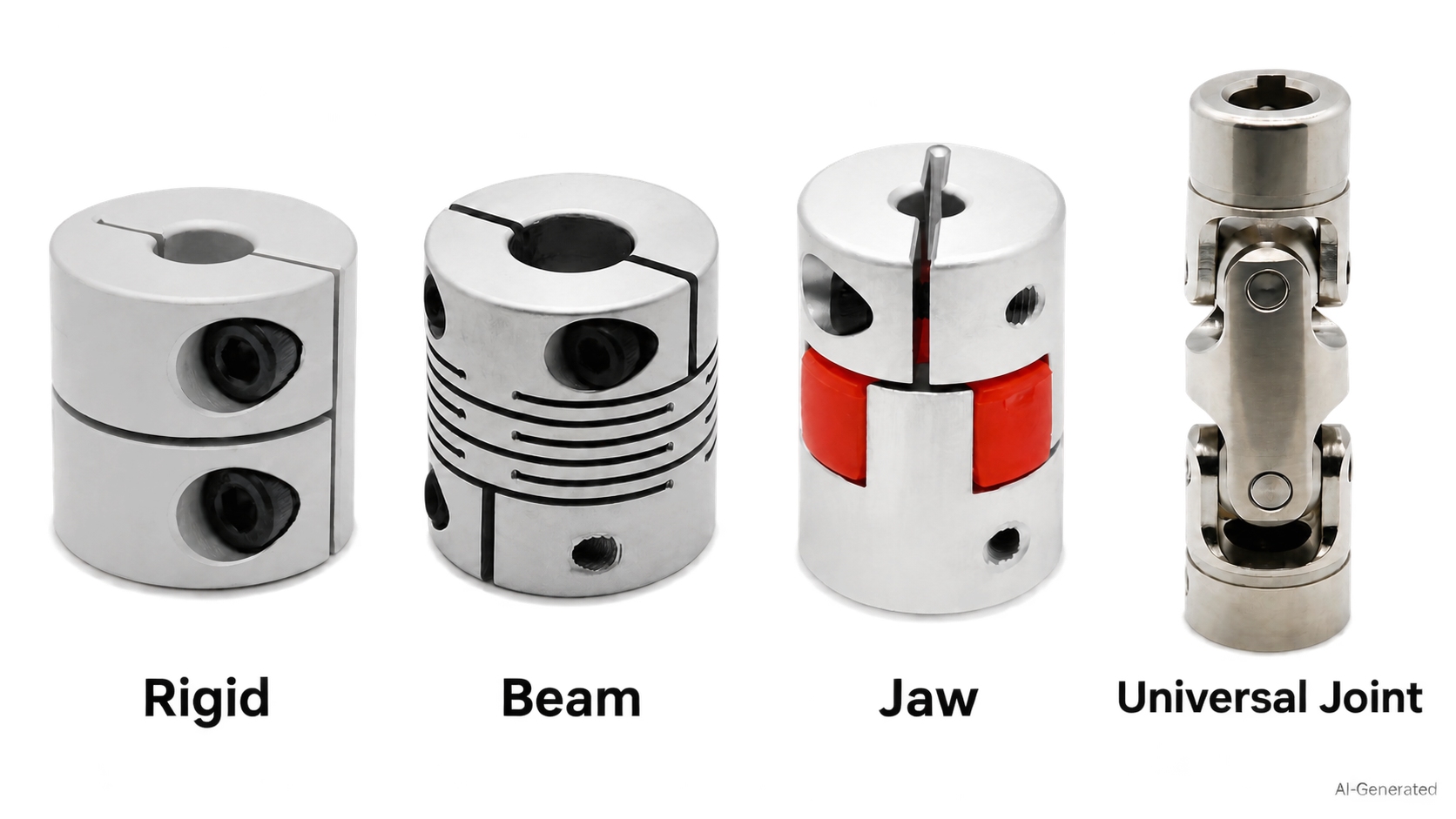
2.1 Rigid Shaft Coupling: Maximum Rigidity and Zero Flexibility
A rigid shaft coupling provides a fixed, continuous mechanical connection between shafts. Manufactured as solid one-piece sleeves or two-piece split clamp-on shaft coupling collars, it introduces no intentional flexure mechanism into the driveline.
Key Advantages
- Exceptional Torsional Stiffness: Delivers zero backlash and virtually zero rotational windup under rated operating loads.
- High Torque Density: Compact envelope relative to its torque transmission capability.
- Minimal Maintenance: Contains no elastomeric wear inserts to degrade and no flexure cuts to fatigue.
Engineering Limitations
- Zero Forgiveness: Incapable of accommodating angular, parallel, or axial misalignment.
- High Bearing Reaction Loads: Any parallel radial offset or angular misalignment induces severe cyclic bending moments, accelerating bearing spalling and seal failure.
Best Applications: Vertical mixers, line shafts supported by common precision-machined housings, and rigidly mounted jackshafts where near-perfect concentricity is guaranteed.
2.2 Helical Beam Coupling: Precision Motion for Light-Duty Drives
A helical beam coupling (often referred to as a curved beam or slit flexible shaft coupling) is machined from a single piece of high-strength aircraft aluminum or stainless steel with continuous spiral cuts.
Key Advantages
- Integral Single-Piece Construction: Eliminates internal mechanical joints, preventing internal fretting and eliminating backlash.
- Zero-Backlash Precision: Highly stable positioning makes it an industry-standard encoder shaft coupler and tachometer connector.
- Low Rotational Inertia: Aluminum versions offer minimal mass, enabling rapid dynamic velocity changes.
Engineering Limitations
- Torsional Windup: The helical beam acts as a torsional spring under heavy torque, causing dynamic phase lag.
- Fatigue Sensitivity & Misalignment Nuance: Single-beam designs accommodate only angular and axial offsets; parallel offset requires dual-beam/multi-beam configurations. Cyclic bending concentrates stress at the cut radii, risking fatigue fracture under high loads.
Best Applications: Precision optical feedback systems, laboratory instrumentation, and as a compact stepper motor coupler for 3D printers and light-duty actuators (for heavy CNC axis drives, disc or preloaded jaw couplings are preferred).
2.3 Flexible Jaw Couplings: The Versatile Shock Absorber
As the most widely implemented industrial flexible shaft coupling, elastomeric jaw couplings (spider couplings) consist of two metallic hubs with intermeshing curved jaws, separated by an elastomeric polyurethane insert (the "spider").
Key Advantages
- Superior Vibration Damping: The polyurethane spider dampens high-frequency harmonic vibrations and absorbs shock impulses via material hysteresis.
- Fail-Safe Mechanical Engagement: If the elastomer wears out or degrades, the intermeshing metal jaws maintain mechanical drive contact ("limp-home mode") to prevent an uncontrolled runaway.
- Tunable Mechanical Properties: Spiders are swappable across various Shore durometers (typically color-coded, e.g., 80 Shore A for maximum damping up to 98 Shore A / 64 Shore D for high rigidity).
Engineering Limitations
- Thermal Boundaries: Standard polyurethane spiders soften and degrade at continuous operating temperatures above 80°C (176°F).
- Backlash in Standard Jaws: Standard straight-jaw designs exhibit small angular clearance; precision motion control requires curved-jaw profiles with preloaded, zero-backlash spiders.
Best Applications: General industrial electric motor shaft coupling systems, centrifugal pumps, rotary screw compressors, conveyor drives, and machine tool auxiliary axes.
2.4 Universal Joint Shaft Coupling: Mastering Severe Angular Misalignment
A universal joint shaft coupling (Cardan joint / U-joint) uses a central cross-pin yoke with needle roller bearings or plain bushings to transmit rotary power across intersecting non-collinear axes.
Key Advantages
- Extreme Angular Tolerance: Accommodates large angular offsets (commonly 10°–20° at moderate speeds, with static or low-speed intermittent limits reaching 30°+), far exceeding any elastic flexure.
- Rugged Mechanical Strength: All-steel cross-and-bearing construction withstands heavy shock loads without slippage.
Engineering Limitations
- Non-Uniform Velocity (Cardan Error): A single universal joint driven at constant angular speed (ωin) outputs a pulsating, fluctuating speed (ωout). This non-uniformity produces secondary torsional vibrations unless mitigated by a properly phased Double-Cardan arrangement with equalized operating angles (β1 = β2).
- Regular Lubrication Required: Cross-needle bearings require periodic lubrication and robust dust seals in harsh or abrasive environments.
Best Applications: Off-highway vehicle steering columns, agricultural PTO drivelines, and industrial articulated multi-axis drives with high angular displacement.
3. Technical Comparison: Rigid vs Beam vs Jaw vs Universal Joint Matrix
3.1 Head-to-Head Performance Matrix
| Engineering Metric | Rigid Coupling | Helical Beam Coupling | Flexible Jaw Coupling | Universal Joint (Single) |
|---|---|---|---|---|
| Torsional Stiffness | Highest (∞) | Low to Medium | Medium to High (Durometer-dependent) | Very High |
| Backlash Rating | Zero Backlash | Zero Backlash | Zero (Curved Preloaded) / Low (Standard) | Low to Medium (Needle/Pin Play) |
| Angular Misalignment | 0.0° (Zero tolerance) | Up to 3.0° – 5.0° | Up to 1.0° – 1.5° | Up to 25.0° – 30.0° |
| Parallel Misalignment | 0.0 mm | Up to 0.25 – 0.5 mm | Up to 0.2 – 0.4 mm | Zero (Requires Double-Cardan) |
| Axial (End-Play) Float | None | Low | Medium (1.0 – 2.0 mm) | Zero (Requires Splined Slip-Shaft) |
| Vibration Damping | None (Transmits shocks) | Low | Excellent (Hysteresis loss) | None |
| Max Practical RPM | High (System balanced) | Very High (Up to 10k+) | Medium to High (Up to 6k-8k) | Low to Medium (< 2500) |
| Maintenance Needs | None | None | Low (Spider inspection/swap) | High (Periodic regreasing) |
| Relative Cost | Low | Low to Medium | Low to Medium | Medium to High |
3.2 Trade-off Analysis: Precision vs Load Capacity vs Tolerance
Selecting the ideal coupling involves three immutable mechanical trade-offs:
- Precision vs. Misalignment: Increasing tolerance for angular or parallel shaft offset requires flexible elements that inherently compromise absolute torsional stiffness.
- Torque Density vs. Damping: Metal-to-metal contact delivers the highest torque per unit volume, but transfers 100% of motor harmonics directly into the driven load. Elastomers damp harmonics, but reduce torque density and introduce temperature vulnerabilities.
- Continuous Smooth Velocity vs. Extreme Angles: Accommodating extreme angular misalignments with U-joints introduces velocity fluctuations that require matched-geometry double joints to eliminate.
4. Application Matching: Selecting the Ideal Motor Shaft Coupling
Selecting the right shaft coupling ultimately depends on the drivetrain motion profile, torque demand, and misalignment conditions. The four application scenarios below map common motor drives to the coupling design that best balances precision, durability, and ease of installation.
4.1 Best Stepper Motor Coupler for CNC & 3D Printers
Desktop CNCs, laser cutters, and 3D printers rely heavily on open-loop NEMA 17 and NEMA 23 stepper drives coupled to precision lead-screws:
The Winner: Curved Jaw Coupling with 98 Shore A Spider or Multi-Beam Helical Coupling.
Why It Works: Open-loop steppers deliver torque in stepped positional impulses, exciting micro-resonance in the driveline. A preloaded curved jaw coupling isolates this stepper micro-resonance, preventing ringing artifacts and surface-layer banding on machined parts. For ultra-compact 5 mm to 8 mm lead-screw attachments, machined aluminum helical beam couplers provide a dependable, zero-backlash solution with negligible inertia.
Selection Tips: Match the spider durometer to the axis — 98 Shore A maximizes stiffness for positional accuracy, while a softer spider adds damping only when audible vibration appears. Always verify the coupling rated torque exceeds the stepper holding torque with an adequate safety margin.
4.2 Servo Motor Couplings for High-Dynamic Positioning Systems
Modern dynamic servo axes execute rapid stop-start velocity profiles with multi-G accelerations:
The Winner: Zero-Backlash Curved Jaw (98 Shore A / 64 Shore D) or Precision Disc / Bellows Couplings.
Why It Works: High servo loop gain requires low rotational inertia and high torsional rigidity. Excessive windup in a low-cost coupling acts as an uncontrolled spring in the control loop, destabilizing it and causing motor hunting, positioning-error alarms, and slow settling during tuning.
Selection Tips: For axes that reverse direction frequently, prioritize a metal bellows coupling for near-infinite torsional stiffness and minimal windup. Where residual vibration damping is still needed, choose a zero-backlash curved-jaw profile rather than a straight-jaw design.
4.3 Heavy-Duty Motor Coupling for Pumps, Compressors, and Gearboxes
Pumping aggregate, hydraulic gear pumps, and screw compressors subject drivetrains to continuous thermal expansion, pressure surges, and cyclic torque ripples:
The Winner: Industrial Flexible Jaw Coupling with Clamping Hubs.
Why It Works: Protects internal pump clearances from axial motor expansion. The elastomeric insert absorbs torsional vibration, lowering acoustic noise and shielding pump mechanical seals from high-frequency fatigue. Clamping hubs also allow hub removal without disturbing shaft alignment.
Selection Tips: Select a spider rated for the continuous operating temperature of the pump — above 80°C (176°F) standard polyurethane softens, so specify a higher-durometer or heat-resistant insert for hot-service applications.
4.4 Extreme Angular Misalignment Drives
For variable-height steering mechanisms, multi-axis articulate spindles, and long-center-distance agricultural shafts:
The Winner: Double Universal Joint Shaft Coupling with Splined Center Section.
Why It Works: Cancels the cyclic angular velocity errors of single joints. A properly phased double-Cardan arrangement comfortably accommodates dynamic angular deflections exceeding 15 degrees without inducing bearing stress or secondary torsional vibration.
Selection Tips: Keep the two operating angles equal and the yokes correctly phased, and schedule periodic greasing of the needle bearings. In abrasive environments, use sealed bearing boots to extend service life.
5. Installation & Maintenance: Preventing Premature Failure
5.1 Precision Alignment: Busting the "Flexible" Myth
The most widespread misconception in mechanical assembly is treating a flexible shaft coupling as an excuse for lax shaft alignment.
The 80/20 Alignment Rule of Thumb
Coupling catalog ratings (e.g., ±3° angular or ±0.5 mm parallel misalignment) represent maximum static survival limits, not ideal continuous operating conditions. Operating near these thresholds generates severe cyclic bending moments that overload supporting motor shaft coupling bearings and induce premature fatigue.
Best Practice: Align equipment to within 1/5 to 1/3 of the maximum catalog tolerance during static assembly using dial indicators or laser alignment tools. This preserves 2/3 to 4/5 of the coupling's compliance capacity for dynamic operational factors, including thermal shaft growth and structural deflection.
5.2 Bore Tolerances & Clamping Methods
Proper torque transmission depends as much on the hub-to-shaft interface as on the coupling body itself.
Shaft Fits and Tolerances: Precision motor shafts should follow ISO h6 to h7 limits, matched to coupling bores machined to ISO H7. Excessive diametral clearance (H8/h8 or looser) causes dynamic mass unbalance, eccentric runout, and fretting corrosion under reversing loads.
Why Clamp-Style Hubs Outperform Set-Screws: In dynamic reversing or high-acceleration applications, set-screws concentrate high stress on a single point, often loosening over time or scoring the shaft surface. A balanced clamping shaft coupling (single-split or two-piece split collar) distributes uniform circumferential frictional pressure, ensuring secure torque transmission without marring the shaft.
Fastener Tightening Torque (Mb): Always torque clamping bolts incrementally with a calibrated torque wrench to the manufacturer's specified screw torque (Ts). Under-torquing leads to micro-slipping and bore galling, while over-torquing strips threads or distorts the hub profile.
5.3 Inspection Checklist & Failure Indicators
To prevent unscheduled downtime, incorporate the following visual and mechanical inspection checkpoints into your preventive maintenance schedule:
| Coupling Type | Key Inspection Checkpoint | Primary Failure Symptom | Corrective Action |
|---|---|---|---|
| Elastomeric Jaw Couplings | Polyurethane Spider wear | Fine rubber dust/debris, noticeable backlash increase, spider hardening (exceeding Shore rating). | Replace spider immediately; inspect for excessive shaft misalignment causing shear fatigue. |
| Helical Beam Couplings | Spiral cut root radii | Micro-cracking at cut roots under optical magnification, permanent torsional set (windup angle lag). | Replace coupling; upgrade to stainless steel or switch to disc/curved-jaw if torque was underestimated. |
| Universal Joint Couplings | Cross spider needle bearings | Noticeable angular/radial play, worn grease seals, audible metallic clattering during reversal. | Purge with fresh EP grease; replace cross assembly if bearing play exceeds manufacturer limits. |
| Rigid Shaft Couplings | Hub clamping bolts & shaft interface | Rust-colored fretting dust around the bore, fastener loosening under cyclic thermal expansion. | Re-torque fasteners to spec; verify that both shafts share identical concentricity. |
FAQ about Shaft Coupling Selection
Q: Can a flexible jaw coupling directly replace a rigid shaft coupling?
Yes, provided torque capacity, spatial envelope, and system stiffness requirements are met. Replacing a rigid coupling with an elastomeric jaw coupling dampens vibration and relieves parasitic bearing reaction loads caused by slight misalignments. However, for precision positioning systems, avoid standard straight-jaw models due to slight torsional backlash; specify a preloaded, curved-jaw model with a high-durometer (98 Shore A or 64 Shore D) spider instead.
Q: Why do helical beam couplings snap during high-torque acceleration?
Because aggressive acceleration torque spikes concentrate high cyclic stresses at the inner radii of the spiral cuts. When repetitive peak torques exceed the fatigue endurance limit of the thinned cross-section, micro-cracks form and propagate into fatigue fractures. To resolve this, increase the coupling outer diameter, upgrade from aluminum to stainless steel, or transition to a disc-pack or preloaded jaw coupling.
Q: How do I choose between a single and double universal joint shaft coupling?
Choose a single U-joint only for intersecting shafts with zero parallel offset where cyclic speed variations (Cardan error) do not disrupt operation. Choose a double U-joint whenever shafts have parallel offset or require constant-velocity output. Arranged with equal operating angles (β₁ = β₂) and correctly phased yokes, the second joint cancels out the rotational fluctuations of the intermediate shaft at the driven output.
Q: What is the best shaft coupling for vibration-heavy electric motor applications?
An elastomeric jaw coupling is the established industry standard. Its polyurethane spider functions as a viscoelastic damper, absorbing cyclic torque spikes and attenuating harmonic vibration transmission to protect motor bearings, mechanical seals, and connected gearboxes.
Q: How do bore size mismatches (e.g., 5mm to 8mm) affect coupling balance?
A bore size mismatch itself does not cause imbalance if precision-machined; the primary issue stems from the hub fastening method. Set-screws displace mismatched shafts radially off-center, generating runout and dynamic mass imbalance that induces noticeable vibration, particularly at elevated operational speeds. For high-speed or dynamic reversing applications, balanced clamp-style split hubs are strongly recommended over set-screws.
Conclusion: How to Choose a Shaft Coupling
Choosing the ideal shaft coupling is a foundational engineering decision that dictates the positioning accuracy, vibration, and service life of your mechanical driveline. Successful powertrain design requires balancing torsional stiffness against real-world shaft misalignment.
When shafts are precision-aligned and concentric, a rigid shaft coupling delivers unmatched torque density, zero backlash, and maximum rigidity. For light-duty motion control, optical encoders, and stepper drives, the single-piece helical beam coupling accommodates fine angular and axial offsets with zero play. When mitigating shock loads, cyclic vibration, and thermal expansion in industrial pumps and motor drives, elastomeric jaw couplings provide ideal vibration damping, tunable spider durometers, and fail-safe protection. Finally, for severe angular articulation beyond flexure limits, the universal joint shaft coupling ensures dependable power transmission across offset axes.
Ultimately, flexible couplings must safeguard against dynamic deflections rather than compensate for poor machining. Always calculate peak torque with proper service factors, prioritize clamp-style hubs over set-screws, and verify continuous RPM deratings to guarantee maximum drivetrain reliability.
Keep Learning
Different-Wire Stepper Motors Wiring & Diagrams Explained
The number of wires coming from a stepper motor tells you how many winding terminals are accessible in the motor, but it does not, by itself, determine the motor type or how the motor should be driven. The internal winding configuration determines which wiring methods are possible, including bipolar, unipolar, series, and parallel connections. This guide explains how a 4 wire stepper motor, 5 wire stepper motor, 6 wire stepper motor, and 8 wire stepper motor are configured, how to identify their windi......
How to Choose a Shaft Coupling: Rigid vs Beam vs Jaw vs Universal Joint
Key Takeaways Shaft Coupling Basics: A shaft coupling transmits torque between driving and driven shafts while accommodating misalignment, vibration, and thermal expansion. The core choice is between rigid (zero flexibility, maximum torque density) and flexible (misalignment-tolerant, vibration-damping) designs. Four Primary Types: Rigid couplings offer zero backlash but require perfect alignment; helical beam couplings provide precision motion for light-duty drives; jaw couplings deliver versatile vi......
Roller Chain Size Chart: ANSI and BS Sizes in mm and Inches
Key Takeaways Identify the chain series first: ANSI and BS-series size codes belong to different dimensional families; changing the units does not change the chain type. Check four details together: Pitch, roller diameter, inner width and number of rows. Matching pitch alone is not enough to choose a replacement. Use the millimeter columns for comparison: Inch equivalents appear beside them, so there is no need to interpret two units in one cell. Count the gaps when measuring pitch: Six consecutive pi......
How to Choose Between Closed-Loop and Open-Loop Stepper Motors
People need the right motor for machine projects. Picking between a closed-loop and open-loop stepper motor shapes machine accuracy and total cost. You can build simple 3D printers with open-loop drives. You can run fast industrial equipment with closed-loop systems. This guide helps you pick the correct motor for your build. Key Takeaways Open-loop stepper systems operate without position feedback, while closed-loop systems use an encoder to monitor actual shaft position. Open-loop systems cannot det......
What Are Pillow Block Bearings? Definition, Working Principle & Applications
Key Takeaways A pillow block bearing is a self-contained bearing unit that combines a rolling-element bearing insert with a rigid housing, designed for shaft support on a flat mounting surface with the shaft axis parallel to the mounting plane. The housing provides structural alignment and load distribution, while the bearing insert handles radial and limited axial loads. Common locking mechanisms include set screws, eccentric collars, and adapter sleeves; each suits different shaft tolerances, vibrat......
Main Types of Servo Motors: AC, DC, and Everything in Between
1. Introduction By leveraging closed-loop feedback to precisely control position, velocity, and torque, servo motors serve as the backbone of modern automation. Yet, application success hinges on matching the right architecture to your load requirements—a task made challenging by the sheer variety of servo motor types available today. In this article, we map motor technology to application requirements through a practical taxonomy covering electrical topology, mechanical construction, performance spec......