Pulley RPM & Ratio Formulas: Timing Belt Speed Guide
9 min
- Driver and Driven Pulley Terminology
- Calculate Ideal RPM from Tooth Counts
- RPM Quick Reference: Common Tooth-Count Combinations
- Pitch Diameter vs Outside Diameter
- Convert RPM to Belt Speed
- A Simple Hypothetical Example
- What a Speed Ratio Does Not Tell You
- FAQ about Pulley Ratio & RPM Formulas for Timing Belts | JLCMC
- About This Pulley Ratio & RPM Guide
Key Takeaways
- For a compatible, correctly engaged timing belt drive, driven RPM = driver RPM × driver teeth / driven teeth.
- Define the ratio convention before using it. Here, reduction ratio i = driver RPM / driven RPM = driven teeth / driver teeth.
- A larger driven pulley turns more slowly; a smaller driven pulley turns faster. Tooth counts determine that ideal relationship.
- Timing pulley pitch diameter is d = pN / π. Outside diameter is a different dimension.
- With pitch p in mm and speed n in rpm, belt speed is v = pNn / (1,000 × 60) in m/s. A speed calculation does not establish load capacity, positioning accuracy, or service life.
A pulley ratio formula relates input shaft speed to output shaft speed. This page shows how to calculate pulley ratio and RPM for a timing belt drive, where pulley tooth counts provide a direct route to the ideal relationship: every revolution moves a known number of belt pitches past each pulley. The scope here is the simple two-pulley synchronous drive; friction drives and multi-shaft layouts follow their own conventions, noted where they differ.
Driver and Driven Pulley Terminology
The driver supplies motion, often from a motor. The driven pulley receives motion through the belt. Label the two roles on your calculation before entering any values; "small pulley" and "large pulley" alone do not identify which one is the input.
| Symbol | Meaning | Unit |
|---|---|---|
| N1 / N2 | Driver / driven pulley tooth count | Teeth |
| n1 / n2 | Driver / driven shaft speed | rpm |
| d1 / d2 | Driver / driven pitch diameter | mm |
| p | Compatible belt and pulley pitch | mm |
| i | Reduction ratio, defined here as n1 / n2 | Dimensionless |
| v | Belt linear speed | m/s |
Calculate Ideal RPM from Tooth Counts
One revolution of a pulley advances the belt by that pulley's tooth count multiplied by pitch. Both pulleys share the same ideal belt speed, so:
pN1n1 = pN2n2
Canceling the common pitch gives the driven-speed formula:
n2 = n1 × N1 / N2
For example, a 20-tooth driver turning at 1,200 rpm and a 40-tooth driven pulley give n2 = 1,200 × 20 / 40 = 600 rpm. The driven pulley needs twice as many passing teeth to complete one revolution, so it turns half as fast.
State which ratio you mean
This article uses i = n1 / n2 = N2 / N1. The example therefore has i = 2:1, a reduction. The output-to-input speed fraction is the reciprocal, n2 / n1 = 1/2.
Both numbers describe the same drive when labeled correctly. A bare statement such as "the ratio is 1:2" is easy to misread. Record the numerator and denominator alongside the value.
RPM Quick Reference: Common Tooth-Count Combinations
For a quick answer without working the formula each time, the table below lists driven speeds for a 20-tooth driver at three common motor speeds. Every row follows the same pulley speed ratio convention (i = n1 / n2) and the n2 = n1 × N1 / N2 relationship, with hypothetical values for calculation practice:
| Driven Teeth | Ratio (i) | n2 at 1,200 rpm | n2 at 1,750 rpm | n2 at 3,450 rpm |
|---|---|---|---|---|
| 10 | 1:2 (speed-up) | 2,400 rpm | 3,500 rpm | 6,900 rpm |
| 20 | 1:1 | 1,200 rpm | 1,750 rpm | 3,450 rpm |
| 40 | 2:1 | 600 rpm | 875 rpm | 1,725 rpm |
| 60 | 3:1 | 400 rpm | 583 rpm | 1,150 rpm |
| 80 | 4:1 | 300 rpm | 438 rpm | 863 rpm |
A driven pulley with fewer teeth than the driver speeds the output up; more teeth slow it down. To calculate pulley ratio and RPM for any combination outside the table, the same formula applies, and the worked example below shows the full calculation with pitch diameter and belt speed.
Pitch Diameter vs Outside Diameter
For a timing pulley, pitch diameter follows:
d = pN / π
Because both pulleys use a compatible pitch, d1 / d2 equals N1 / N2. The ideal speed formula can therefore also be written as n2 = n1 × d1 / d2.
Use pitch diameters in that equation. The same relationship drives the pulley size calculation for a target speed ratio: pick the tooth counts, and d = pN / π returns the pitch diameters to order. It is also how to calculate pulley ratio and RPM when only diameters are measurable and tooth counts are not. A measurement across the tooth tips gives outside diameter, which depends on the tooth geometry and is not the same value. Pulley flanges can make an outside measurement even less relevant to the calculation; for identification background, review the timing pulley types guide. The pitch-line geometry behind these formulas is documented in belt-maker design references such as the Gates Mectrol belt sizing guide.
What About Mechanical Advantage?
Searches for a pulley formula also surface the mechanical advantage pulley formula, which belongs to a different family of pulleys. Mechanical advantage describes a rope-and-pulley block arrangement multiplying force (roughly, the number of supporting rope segments); a timing belt drive is a positive-drive speed and torque relationship between two rotating shafts. The two formulas share the word pulley and little else. For a synchronous drive, the torque relationship follows the speed relationship inversely: a 2:1 speed reduction pairs with roughly a 2:1 torque increase at the driven shaft, less losses.
Convert RPM to Belt Speed
At the pitch line, each revolution advances the belt by pN millimeters. The belt speed formula multiplies that by the rotational speed and converts millimeters per minute to meters per second:
v = pNn / (1,000 × 60)
Here 1,000 converts millimeters to meters and 60 converts minutes to seconds; keeping them separate makes the unit path visible. An equivalent form, when pitch diameter is entered in millimeters, is:
v = πdn / (1,000 × 60)
Either pulley should give the same ideal belt speed. This provides a useful calculation check: different answers usually indicate an inconsistent diameter, tooth count, speed, or unit.
A Simple Hypothetical Example
To calculate pulley ratio and RPM end to end, use these teaching inputs: p = 5mm, N1 = 20, N2 = 40, and n1 = 1,200 rpm. No product rating or availability is implied.
| Quantity | Calculation | Result |
|---|---|---|
| Reduction ratio | i = 40 / 20 | 2:1 reduction |
| Driven speed | n2 = 1,200 × 20 / 40 | 600 rpm |
| Driver pitch diameter | d1 = 5 × 20 / π | ≈ 31.831mm |
| Driven pitch diameter | d2 = 5 × 40 / π | ≈ 63.662mm |
| Belt speed from driver | 5 × 20 × 1,200 / (1,000 × 60) | 2 m/s |
| Belt speed from driven | 5 × 40 × 600 / (1,000 × 60) | 2 m/s |
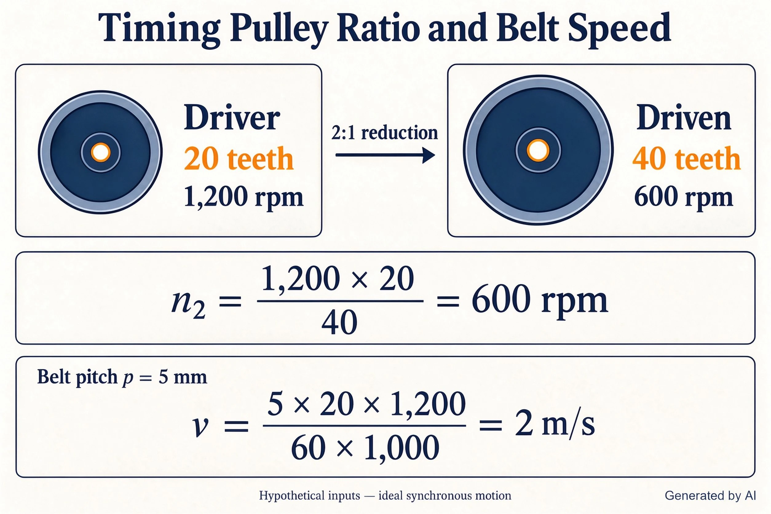
chart of driven rpm for common tooth-count pairs
If the driver still runs at 1,200 rpm but the pulley tooth counts are reversed, the output becomes 1,200 × 40 / 20 = 2,400 rpm. This illustrates why the input and output labels matter; simply knowing that the pulleys have a 2:1 size relationship is insufficient to determine whether the drive speeds up or slows down.
What a Speed Ratio Does Not Tell You
The formula assumes compatible tooth geometry and ideal engagement without tooth jumping. It describes motion. It does not calculate allowable torque, required belt width, bearing loads, acceptable acceleration, positioning error, or fatigue life.
Two drives can have the same tooth-count ratio while using different pulley sizes, widths, center distances, and tension settings. Those differences can change belt bending, engagement, installation space, and operating demands even though the calculated RPM ratio is unchanged.
Center distance affects belt length and wrap geometry, but does not change the ideal tooth-count ratio by itself. Complete the geometry and rating checks using the relevant belt system's technical information; design-practice references treat engagement, load, and installation as separate checks (notably the SDP/SI timing belt design suggestions). The JLCMC timing belt and pulleys matching guide provides broader specification checks, and our v-belt dimensions guide covers the friction-drive side, where belt length and datum-diameter conventions replace the tooth-count method.
FAQ about Pulley Ratio & RPM Formulas for Timing Belts | JLCMC
Q: Does a larger driven pulley increase or decrease RPM?
With driver speed unchanged, a larger compatible driven timing pulley has more teeth and rotates more slowly.
Q: Does a smaller driver pulley increase the output speed?
With driven tooth count and driver RPM unchanged, fewer driver teeth reduce output RPM. Apply n2 = n1 × N1 / N2 to avoid reversing the relationship.
Q: Does changing center distance change the ratio?
It does not change the ideal ratio of unchanged timing pulley tooth counts. It does change the belt-length and engagement checks.
Q: Can I calculate RPM using pulley outside diameters?
For timing pulleys, use tooth counts or pitch diameters. Outside and flange diameters describe different geometry.
Q: Can I use the result to choose a belt?
It supplies the motion requirement. Belt selection also needs geometry, load, duty, tension, and the applicable product ratings.
Q: What is the pulley RPM formula?
For a timing pulley rpm calculation, the driven-pulley speed formula is n2 = n1 × N1 / N2: driver rpm multiplied by driver teeth, divided by driven teeth. The pulley rpm formula for belt speed follows as v = pNn / (1,000 × 60), with pitch p in millimeters.
About This Pulley Ratio & RPM Guide
To calculate pulley ratio and RPM for any timing belt drive, label the driver and driven pulleys, define the ratio convention, and work the tooth-count formula. Use pitch geometry and consistent units to calculate belt speed, then check that both pulleys give the same result. The formulas answer the motion question; the mechanical checks around it belong to the belt system's own data.
Browse the JLCMC timing pulley category and timing belt category to review current specifications. Confirm tooth profile, pitch, width, shaft interface, and application ratings before selection.
Keep Learning
Pulley RPM & Ratio Formulas: Timing Belt Speed Guide
Key Takeaways For a compatible, correctly engaged timing belt drive, driven RPM = driver RPM × driver teeth / driven teeth. Define the ratio convention before using it. Here, reduction ratio i = driver RPM / driven RPM = driven teeth / driver teeth. A larger driven pulley turns more slowly; a smaller driven pulley turns faster. Tooth counts determine that ideal relationship. Timing pulley pitch diameter is d = pN / π. Outside diameter is a different dimension. With pitch p in mm and speed n in rpm, be......
What Is the Voltage of a NEMA 17 Stepper Motor?
When designing or building precision electronics projects, understanding power requirements is critical for optimal performance. Choosing the correct NEMA 17 stepper motor voltage can often feel confusing given all the terminology and standards one must consider when choosing a NEMA 17 stepper motor. To help you navigate winding specifications, driver limits, and performance trade-offs, keep the following core concepts in mind before diving into our detailed guide. Key Takeaways: NEMA 17 refers to a m......
Different-Wire Stepper Motors Wiring & Diagrams Explained
The number of wires coming from a stepper motor tells you how many winding terminals are accessible in the motor, but it does not, by itself, determine the motor type or how the motor should be driven. The internal winding configuration determines which wiring methods are possible, including bipolar, unipolar, series, and parallel connections. This guide explains how a 4 wire stepper motor, 5 wire stepper motor, 6 wire stepper motor, and 8 wire stepper motor are configured, how to identify their windi......
How to Choose a Shaft Coupling: Rigid vs Beam vs Jaw vs Universal Joint
Key Takeaways Shaft Coupling Basics: A shaft coupling transmits torque between driving and driven shafts while accommodating misalignment, vibration, and thermal expansion. The core choice is between rigid (zero flexibility, maximum torque density) and flexible (misalignment-tolerant, vibration-damping) designs. Four Primary Types: Rigid couplings offer zero backlash but require perfect alignment; helical beam couplings provide precision motion for light-duty drives; jaw couplings deliver versatile vi......
Roller Chain Size Chart: ANSI and BS Sizes in mm and Inches
Key Takeaways Identify the chain series first: ANSI and BS-series size codes belong to different dimensional families; changing the units does not change the chain type. Check four details together: Pitch, roller diameter, inner width and number of rows. Matching pitch alone is not enough to choose a replacement. Use the millimeter columns for comparison: Inch equivalents appear beside them, so there is no need to interpret two units in one cell. Count the gaps when measuring pitch: Six consecutive pi......
How to Choose Between Closed-Loop and Open-Loop Stepper Motors
People need the right motor for machine projects. Picking between a closed-loop and open-loop stepper motor shapes machine accuracy and total cost. You can build simple 3D printers with open-loop drives. You can run fast industrial equipment with closed-loop systems. This guide helps you pick the correct motor for your build. Key Takeaways Open-loop stepper systems operate without position feedback, while closed-loop systems use an encoder to monitor actual shaft position. Open-loop systems cannot det......