Drawer Slide Selection Guide for Equipment Trays: Sizing, Load Calculation & Locking
11 min
- Define the Service Task Before the Rail Length
- Understand What the Lock Actually Does
- Calculate Gross Load and Identify Its Position
- Separate Rail Strength from Cabinet Stability
- Compare Functions at the Specification Stage
- Integrate Cables and Lock Releases into the Tray
- How to Choose and Validate a JLCMC Slide
- FAQ about Drawer Slides for Equipment Trays
Key Takeaways
Gross Load First: Calculate the moving assembly's gross load, including the tray, brackets, equipment and attached accessories.
Travel, Not Rail Length: Specify the actual travel needed for service access; nominal rail length alone does not establish that travel.
Know Your Lock: Distinguish a positive lock, a detent, a soft-close feature and a disconnect mechanism.
Three Independent Checks: Treat slide capacity, mounting-bracket strength and cabinet tipping resistance as separate checks.
Test Full Cable Motion: Route cables through the complete open-and-close motion before approving the design.
Confirm Ordering Details: Confirm pair quantity, handedness, mounting orientation and rating conditions for the selected part number.
An instrument may fit inside a cabinet and still be difficult to service. Connectors face the rear, mounting screws sit behind adjacent equipment, and inspection requires reaching into a narrow opening. A pull-out tray can bring those features into reach, but its slide system must do more than carry the instrument's weight.
As the tray extends, the load moves away from the cabinet, cables change shape and the operator interacts with a projecting assembly. Locking behavior, usable travel, mounting orientation and the stability of the whole cabinet therefore belong in the initial design. This guide explains how to turn a service-access requirement into a drawer-slide specification.
Define the Service Task Before the Rail Length
Start by listing what must be reached when the tray is open. A technician changing a front-mounted filter may need much less travel than somebody removing a rear connector. The tray must clear not only the cabinet opening but also the door, bezel, handle, neighboring controls and the tools required for maintenance.
Draw the closed position and the service position together. Mark the rear-most component that needs access and identify the hand or tool approach. A connector can be visible but still impossible to unplug if its release tab faces an obstruction. Include the space needed to lift out the equipment after its fasteners are removed.
Then translate that access requirement into travel. Partial extension, full extension and overtravel describe how far the moving member projects relative to its installed length. Three members do not, by themselves, establish an exact travel dimension for every design. Use the chosen slide's drawing to confirm the fully closed and fully extended positions.
When planning an equipment tray, travel, cabinet depth, side clearance, and disconnect requirements act as interdependent selection parameters. Reviewing these factors against an engineering checklist ensures the assembly delivers full service access without compromising mechanical rigidity. Explore standard and heavy-duty options in the JLCMC Drawer Slides Catalog.
Understand What the Lock Actually Does
A positive lock requires a deliberate release action before the tray moves from its locked position. A detent supplies resistance to movement at a position, but may release when sufficient force is applied. Soft-close mechanisms manage the final closing movement. A disconnect allows one rail member to separate for removal. These functions can coexist, but none should be inferred from another.
For a service tray, a lock-open function may help hold the working position, while a lock-closed function may keep the tray from moving during ordinary handling. The required retaining force and operating conditions still need verification. A drawer lock is not automatically rated as a vehicle transport restraint or a machine safety interlock.
JLCMC's DHHC heavy-duty drawer slide series provides a relevant starting point. The product page identifies a three-track, 53 mm series made from SPCC with blue-and-white zinc plating. Its feature field lists open/close locking and an inner-rail retractable feature; left- and right-side selections are shown. Confirm the actual release and removal sequence from the selected drawing or sample instead of interpreting the feature label as a complete operating instruction.
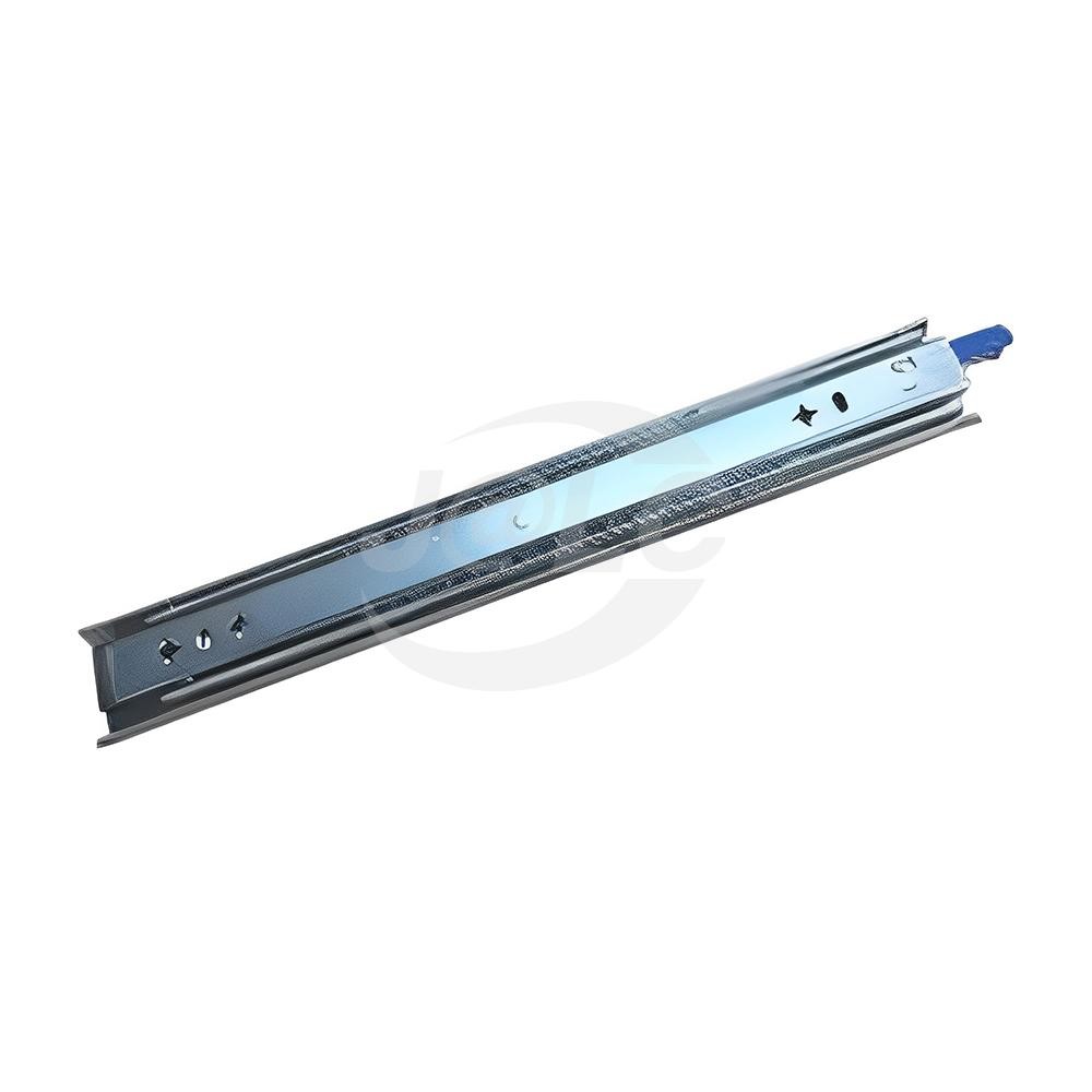
JLCMC DHHC series product image. Select the required length and side, then verify the complete installation and rating details.
Calculate Gross Load and Identify Its Position
The payload is only part of the moving mass. Add the tray, brackets, fasteners, permanently attached cable-management parts and any accessories that travel with the assembly. Include normal service items if the work procedure allows them to rest on the tray. Do not silently turn an equipment tray into a work platform by ignoring how it will actually be used.
Drawer slide load ratings depend on the manufacturer's specified test conditions and installation configuration. Verify whether the stated capacity applies to a single slide or a matched pair, and confirm the permitted mounting orientation, extension position, and applicable service conditions before selecting a slide. A published load rating does not necessarily mean all products have undergone identical dynamic validation, so always consult the specific model's technical documentation for its verified operating envelope. Material thickness alone does not determine capacity—raceway geometry, ball bearing quantity and hardness, and track profile all dictate allowable dynamic loads. Sizing must always be verified against the exact mounting configuration and service duty cycle.
Record where the mass sits. Two trays with equal gross weight can load their attachments differently if one carries a compact instrument near the front and the other distributes components along its depth. During extension, the external load creates a bending moment that the rails, fasteners and cabinet structure must resist.
An Illustrative Moment Calculation
Suppose a 20 kg moving assembly has its center of gravity 0.45 m in front of a chosen cabinet reference plane when extended. Its gravitational moment about that plane is approximately $20 \times 9.81 \times 0.45 \approx 88.3\ \text{N·m}$. This moment is a system-level estimate about the stated reference plane. It is not the bending moment at every point along the slide, nor can it be converted directly into a slide load rating without considering the slide geometry, mounting points, load distribution, and structural stiffness.
If the same center of gravity moves to 0.60 m, the moment becomes approximately $117.7\ \text{N·m}$ although the mass has not changed. That is why additional travel should be justified by access needs and checked against the complete assembly, rather than added without reviewing its structural effect.
Separate Rail Strength from Cabinet Stability
A sufficiently rated slide can still be installed in a cabinet that tips when the tray opens. Evaluate the combined center of gravity of the cabinet, fixed equipment and moving tray throughout travel. Opening a second drawer or placing a service tool on the first tray can alter the result again.
For an initial static stability check, the combined center-of-gravity projection should remain within the cabinet's effective support footprint. The final assessment must also consider applicable operating forces, dynamic effects, floor conditions, and foreseeable simultaneous loading. Where required, provide suitable anchoring or an engineered interlock system; increasing the rail capacity does not compensate for an inadequate footprint.
Also inspect the rail attachment locally. A narrow bracket can twist, a thin wall can deflect and a fastener group can be overloaded. The slide rating does not validate these structures. Position attachment points so the load is transferred into appropriate frame members, with fasteners and hole patterns that match the actual installation requirements.
Compare Functions at the Specification Stage
The final row of the table deserves special attention. Rotating a slide by 90 degrees into a flat (bottom-mount) position fundamentally alters how the ball bearings and raceways carry the load. In a flat orientation, standard ball bearing slides experience a severe reduction in capacity compared to their side-mount rating, and many heavy-duty three-track slides do not permit flat mounting at all. Always consult the official JLCMC technical specifications to confirm permitted mounting orientations and derating factors before committing to a flat-mount layout.
| Design choice | What it contributes | What it does not establish | Verification needed |
|---|---|---|---|
| Full extension or overtravel | Greater access beyond the opening | Load capacity at that extension | Selected length's travel and rating conditions |
| Lock-open | Deliberate retention at the open position | Cabinet stability or unlimited holding force | Release access and permitted retention load |
| Lock-closed | Retention when stored | Transport certification or a safety interlock | Duty, shock and operating conditions |
| Disconnect feature | Removal of the moving member | Safe support after separation | Removal sequence and handling plan |
| Soft-close | Controlled final closing motion | Positive locking | Closing behavior with the actual payload |
| Flat mounting | A possible alternative installation envelope | Retention of a side-mount rating | Explicit approval and a flat-mount capacity |
Integrate Cables and Lock Releases into the Tray
Model a realistic cable bundle, not a single idealized line. Power leads, data cables and hoses may have different bend limits and strain-relief needs. At full extension, connectors should not become the travel stop. At closure, the bundle should not fold into the rail, lock lever or cabinet edge.
Place the moving and fixed strain-relief points deliberately. Check the whole motion while observing where the bundle changes direction. A generous loop can solve tension at full extension yet create a snag during closure. A cable carrier or guided loop may be appropriate, but its own bend-radius and mounting requirements must fit the available space.
Test access to both locking controls with the real front panel installed. If two sides need coordinated release, determine how the operator can do so while maintaining control of the tray. A release that is comfortable on an empty slide can become awkward beneath a projecting instrument.
How to Choose and Validate a JLCMC Slide
Select the Family and Configuration
Begin with the JLCMC drawer slide category, then narrow to a family offering the required locking and travel behavior. For DHHC, confirm the selected left/right configuration and ordering quantity. A page offering separate sides should not be assumed to supply a matched pair automatically.
Collect the Part-Number Data
For the selected part number, collect its length, travel, side clearance, mounting-hole positions and load data. Clarify whether the load is per slide or per pair, and what orientation, extension and operating conditions the rating covers. If a required value is absent, resolve it before finalizing the hardware rather than treating the heavy-duty category name as a numeric specification.
Build and Test a Representative Assembly
Build a representative assembly using the intended tray, supports, payload and cable routing. Check motion empty and loaded; observe deflection, lock engagement and release access at full extension. Cycle it under the intended service pattern and define acceptance criteria before testing, such as clear connector access, repeatable locking and no contact between cables and moving rails.
FAQ about Drawer Slides for Equipment Trays
Q: Does a three-track slide always give full extension?
Do not infer exact travel from the number of tracks. Confirm the drawing for the selected series and length, including any extension limits or extra travel beyond the cabinet opening.
Q: Can a lock-open slide support a person leaning on the tray?
Only if that use has been explicitly included in the assembly design and relevant ratings. An equipment-load rating does not establish suitability as a step, seat or human-support platform.
Q: Should both slides have locking mechanisms?
Follow the product's intended arrangement. Some systems use a locking slide and companion slide, while others use handed locking members. Verify the selected configuration and how the user releases it.
Q: Is stainless steel automatically better for a heavy tray?
Material choice and load capacity are separate decisions. Environmental resistance, geometry, bearing arrangement, fastening and rating conditions all matter. Choose based on the application and confirmed specifications.
Q: Can I shorten a slide to fit a shallow cabinet?
Do not assume that cutting a slide preserves its travel stops, bearings, locks or rating. Select an appropriate catalog length or obtain a specifically approved design for the available depth.
Q: Why test the tray if the slides have a load rating?
The rating does not evaluate your cabinet walls, bracket stiffness, cable bundle, equipment location or user access. Assembly testing checks how those elements interact in the actual configuration. For troubleshooting issues such as alignment errors or mechanical friction, see our practical guide on why drawer slides get stuck and how to fix them.
Conclusion: Drawer Slide Selection for Equipment Trays
A useful equipment tray begins with a defined service task. Match travel and locking to that task, then check gross load, extension moment, mounting structure, cabinet stability and cable motion. Select the exact drawer-slide configuration only after those requirements are clear, and validate the completed assembly under its intended use.
Popular Articles
Keep Learning
Drawer Slide Selection Guide for Equipment Trays: Sizing, Load Calculation & Locking
Key Takeaways Gross Load First: Calculate the moving assembly's gross load, including the tray, brackets, equipment and attached accessories. Travel, Not Rail Length: Specify the actual travel needed for service access; nominal rail length alone does not establish that travel. Know Your Lock: Distinguish a positive lock, a detent, a soft-close feature and a disconnect mechanism. Three Independent Checks: Treat slide capacity, mounting-bracket strength and cabinet tipping resistance as separate checks.......
Threaded Standoff vs Spacer: What Is the Difference?
Key Takeaways Threaded standoffs provide both spacing and threaded attachment points, making them ideal for modular assemblies and PCBs. Spacers are unthreaded sleeves that work with through-bolts to maintain gaps in clamped assemblies, offering a simpler and more economical solution. The right choice depends on the load path, assembly sequence, material, and service environment - not just appearance or catalog naming. A threaded standoff and a spacer can look almost identical on a workbench. Both cre......
How to Choose a Threaded Standoff for PCB and Mechatronic Assemblies
Key Takeaways Select the right configuration: Choose male-female, female-female, or male-male thread configurations based on the two mating interfaces and the intended assembly sequence. Treat height as a tolerance stack: Standoff body length must satisfy clearance, electrical, thermal, and connector requirements across the full tolerance range, not just the nominal dimension. Verify thread engagement: Check male thread length against tapped-hole depth and upper screw length against usable female thre......
Threaded Standoff Guide: Types, Sizes, Materials and Applications
Key Takeaways Thread configuration first: Choose female-female, male-female or male-male based on how both sides of the assembly attach — thread config is the most practical way to classify a threaded standoff. Body length is the critical dimension: Standoff length refers to the distance between supporting faces, not total physical length. Reading the wrong length causes incorrect mounting height or screw bottoming. Material affects more than strength: Brass, stainless steel, carbon steel, aluminum an......
Ball Nose End Mill Stepover: Scallop Height and Effective Diameter
Key Takeaways Geometric Control: Stepover directly controls geometric scallop height, but it does not automatically guarantee a measured Ra value. Cusp Height Formula: For a ball radius $R$ and pass spacing $s$ on a flat surface, the ideal cusp height is $h = R - \sqrt{R^2 - \frac{s^2}{4}}$. Tool Radius Advantage: A larger ball can use wider spacing for the same ideal cusp, provided it can reach the required geometry without gouging. Effective Diameter: The active cutting diameter near the tool tip ca......
Manual SMT Stencil Printer Sizing: Print Area, PCB Support and Frame Fit
Key Takeaways Different dimensions: Worktable size, effective print area, board envelope, and stencil frame size are different dimensions. Check the full pattern: Check the whole aperture pattern in its intended orientation, including clearance for the printing stroke. Thickness is not enough: A compatible board thickness does not prove that a populated underside or a support fixture will fit. Support and contact: Stable support and close stencil-to-board contact are necessary for a repeatable printin......