Polyurethane Bumper Energy Calculation: Impact Kinetic Formulas, Stroke & Duty Cycles
12 min
- Define the Stop's Role First
- A Verified JLCMC Product Starting Point
- Calculate the Energy Arriving at Contact
- Work Backward from the Available Stopping Distance
- Why Hardness Alone Cannot Select the Bumper
- Compare the Information Each Selection Attribute Provides
- Repeated Stops Change the Requirement
- Design the Contact and Mounting Arrangement
- Build a Selection Brief and Verify the Result
- FAQ about Polyurethane Bumper Energy Calculation
Key Takeaways
- Impact energy depends on contact velocity squared, so a small speed change can materially alter the stopping event.
- Physical bumper height is not the same as permitted compression or usable stopping distance.
- Include work from a drive force that continues during compression, plus gravity or rotational effects where applicable.
- Hardness describes indentation resistance; it is not an energy rating or a complete force-deflection curve.
- Repeated impacts require a duty assessment as well as a per-impact check.
- A polyurethane bumper should not be treated as a certified emergency-stop device without an appropriate system design and explicit product evidence.
A polyurethane bumper can look substantial and still be wrong for a moving assembly. The part may fit the available thread, match the desired hardness and survive a gentle hand-operated trial, yet receive a very different impact during the real machine cycle.
Selecting an end stop begins with the event it must handle: the mass arriving at the stop, its actual contact velocity, the force still driving it, and the distance available to slow it down. Material hardness and mounting dimensions matter, but they do not replace that description. This guide develops a practical selection brief for polyurethane bumpers and explains where application testing or additional product data becomes necessary.
Define the Stop's Role First
An elastomer bumper may cushion a manually moved panel, limit occasional overtravel or receive a planned contact during a machine cycle. These are different duties. An occasional end stop can experience a rare but severe event, while a production stop may receive smaller impacts thousands of times over its service life.
Write down whether contact is expected in normal operation and what controls the approach speed. A motion axis that normally decelerates before contact presents a different requirement from a slide that strikes the bumper at full travel speed. Keep the normal stopping function and any separate protective function clear in the design record.
Also define what “successful stopping” means. The assembly may need to avoid metal-to-metal contact, remain within a displacement envelope, limit force into a bracket, settle without excessive rebound, or preserve an alignment datum. A part that survives the impact does not necessarily satisfy all of those requirements.
A Verified JLCMC Product Starting Point
JLCMC's HJCJ polyurethane shock-absorbing material series uses a cylindrical form with a thermally bonded bolt mounting arrangement. The series page offers material and hardness selections, including ether and ester polyurethane options. The catalog's Shock Absorbing Material category also includes other mounting shapes and forms.
These details establish available product families and selection attributes. They do not establish an allowable impact energy for an arbitrary chosen diameter and length. Obtain the applicable compression, force or energy information for the exact variant before using it as a calculated machine end stop.
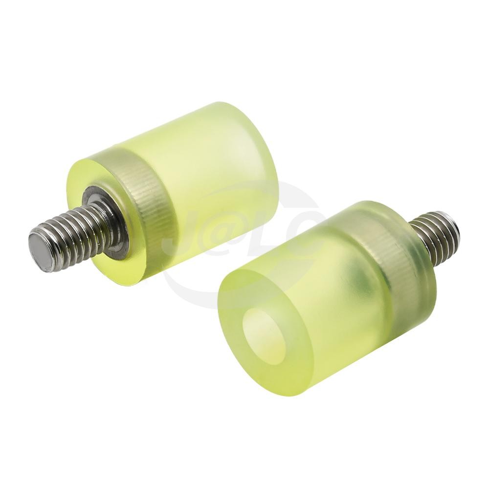
JLCMC HJCJ series product image. The pictured shape identifies the family; material, hardness and dimensions must be checked for the selected variant.
Calculate the Energy Arriving at Contact
For a translating mass with no continuing drive force, the kinetic energy at first contact is:
$$E = \\frac{1}{2} \\times m \\times v^{2}$$
Use mass in kilograms and velocity in meters per second to obtain energy in joules. The velocity is the speed immediately before the bumper begins compressing, not necessarily the average travel speed entered in a cycle-time estimate.
As an illustrative example, a 5 kg carriage contacting a stop at 0.4 m/s carries 0.4 J of kinetic energy. At 0.8 m/s, the same carriage carries 1.6 J. Doubling velocity quadruples energy. These values are a physics example and do not imply that any HJCJ variant is rated for either event.
Include continuing drive work
If a constant 100 N force continues to push the carriage through 5 mm of stopping travel, it adds 100 × 0.005 = 0.5 J of work. In the 0.4 m/s example, the total energy presented to the stopping system would therefore be 0.9 J under those simplified assumptions.
For a vertical stop, include the effect of gravity during the stopping motion. For a rotating mechanism, use the appropriate rotational kinetic energy and the geometry relating rotation to bumper displacement. Connected motors, gears or other moving elements may contribute energy that a payload-only calculation misses.
A rigorous mechanical energy balance separates pure kinetic energy, actuator drive work, and gravitational potential energy across the stopping stroke:
$$E_{total}=E_{k}+W_{drive}+E_{potential}=\\frac{1}{2}mv^{2}+F_{drive}\\cdot s+mgs\\sin (\\theta )$$
where $m$ is the moving carriage mass (kg), $v$ is contact velocity immediately before compression (m/s), $F_{drive}$ is the sustained motor or pneumatic cylinder thrust force (N), $s$ is the usable bumper compression stroke (m), and $\\theta $ is the axis inclination angle. Unlike hydraulic shock absorbers that maintain near-constant deceleration, polyurethane exhibits non-linear compression stiffening. The average and peak impact forces transferred to machine frames can be calculated as:
$$F_{avg}=\\frac{E_{total}}{s},F_{peak}\\approx c_{u}\\cdot F_{avg}$$
where $c_{u}$ is the progressive stiffening coefficient ($c_{u}\\approx 1.5\\sim 2.2$ for cylindrical elastomer bumpers depending on durometer and deformation ratio).
Work Backward from the Available Stopping Distance
A bumper slows the moving assembly as it deforms. The energy handled over the loading stroke is related to the area under its force-displacement curve. The exact curve depends on the material, geometry and loading conditions; a constant-force assumption does not describe every elastomer bumper.
For an initial scale check, average resisting force is energy divided by stopping distance. If an illustrative 0.9 J event is handled over 5 mm, the average force is 180 N. If the same energy must be handled over 2 mm, it becomes 450 N. Peak force may be higher, and neither number is a selected product's rating.
This simple comparison explains why a very short stop can impose substantial loads on the bracket and moving assembly. It also shows why a larger-looking bumper is not enough evidence: the permitted working compression and actual force curve must fit the application.
Do not equate height with travel
A 20 mm-high elastomer does not automatically provide 20 mm of useful stopping travel. Its allowed compression is limited by the material, shape, mounting and duty. Leave space for the deformed shape and ensure that surrounding metalwork does not become an unintended hard stop before the approved working stroke is reached.
Where a mechanical travel limit is required, coordinate its position with the bumper's permitted compression. The hard limit, support structure and bumper form one stopping arrangement. Their relative positions should be defined in the drawing rather than adjusted by trial until the impact sounds acceptable.
Why Hardness Alone Cannot Select the Bumper
Durometer indicates resistance to indentation under a defined measurement method. It does not directly state how much energy a complete part handles, how far it compresses or how much it rebounds. Geometry and the freedom of the material to bulge also affect the response.
Elastomer mechanics dictate that solid polyurethane is essentially incompressible in bulk volume (Poisson's ratio $\\nu \\approx 0.49\\sim 0.50$). Under compressive load, it accommodates displacement solely through lateral bulging. The compressive stiffness and load capacity are governed by the geometric Shape Factor ($S$), defined as the ratio of loaded area to total free-to-bulge area:
$$S=\\frac{A_{loaded}}{A_{free}}=\\frac{\\frac{\\pi D^{2}}{4}}{\\pi Dh}=\\frac{D}{4h}$$
For a cylindrical bumper bonded to a rigid backing plate, increasing the diameter-to-height ratio restrains lateral bulging, dramatically increasing the apparent compressive modulus $E_{a}\\approx E_{0}(1+2S^{2})$ compared to initial Young's modulus $E_{0}$. Consequently, Shore A durometer indicates only initial polymer hardness, whereas total impact energy absorption and usable deflection stroke are determined by the shape factor $S$ and the safe working strain limit ($\\leq 30\\%\\sim 35\\%$ of free height).
For procurement, specify the full material and geometry rather than ordering “a yellow 90-shore bumper.” Color is not a reliable substitute for a material designation, and a hardness number without its scale is incomplete. If replacing a part, preserve the original dimensional and material requirements or reassess the stopping event.
Compare the Information Each Selection Attribute Provides
| Selection input | What it helps establish | What it cannot establish alone | Next check |
|---|---|---|---|
| Mass and contact velocity | Translational kinetic energy | Continuing drive or gravity work | Complete event energy balance |
| Bumper height and envelope | Physical fit | Permitted working compression | Variant-specific deflection information |
| Hardness and material designation | Material identity and indentation behavior | Whole-part impact capacity | Geometry and force-deflection data |
| Thread and bonded attachment | Mounting interface | Strength of the receiving bracket | Attachment and support load path |
| Energy per impact | Severity of one event | Repeated-duty temperature or life | Frequency, cooling and validated duty |
| Number of bumpers | Potential distribution of the event | Equal sharing | Contact timing, alignment and stiffness |
Use the table as a gap check. A drawing may provide excellent dimensions while leaving dynamic performance unspecified. That is a reason to gather another piece of information, not to invent a capacity from the dimensions.
Repeated Stops Change the Requirement
A single successful impact demonstrates little about long-term repeated duty. Elastomer deformation stores and dissipates energy, and part of the stored energy can return as rebound. Repeated loading can also create temperature rise and changes in behavior that a slow manual check will not reveal.
Record impacts per minute or hour, expected pauses, ambient conditions and whether the bumper remains compressed between cycles. Calculate the incident energy rate as a comparison metric, while recognizing that not all incident energy necessarily becomes heat in the bumper. The fraction dissipated and the ability to reject heat depend on the material and application.
Repeated-stop engineering evaluations require checking the hourly energy absorption rate and thermal dissipation capacity:
$E_{hour}=E_{total}\\times N_{cycles/hour}$
During each deceleration cycle, polyurethane dissipates impact energy into internal thermal energy through viscoelastic hysteresis loss ($E_{dissipated}=\\eta \\cdot E_{total}$, where loss factor $\\eta \\approx 0.15\\sim 0.35$). If heat generation outpaces convective dissipation from the bumper surface, internal core temperatures will rise rapidly. Above $70^{\\circ }C\\sim 80^{\\circ }C$, polyurethane experiences severe thermal softening, permanent compression set, and tensile tearing along bonded interfaces. Emergency overtravel stops must therefore be sized differently from high-cycle production stops.
Design the Contact and Mounting Arrangement
Arrange the moving face so it engages the bumper as intended. Edge contact, an angled strike or a misaligned guide can concentrate deformation and introduce lateral forces. A threaded stud locates the part, but the supporting bracket still has to carry the resulting forces and moments.
If two bumpers are intended to share an impact, control their positions and the moving surface's alignment. One bumper contacting earlier can receive a larger share before the second engages. Dividing total energy by two is justified only when the mechanical arrangement actually supports that sharing assumption.
Keep the contact area free of sharp edges and contamination that could damage the elastomer. Check exposure to oil, coolant, cleaning chemicals and temperature against the selected material's data. Do not assume every polyurethane formulation behaves identically in the same environment.
Build a Selection Brief and Verify the Result
For the JLCMC product inquiry or internal design review, provide the moving mass, measured or justified contact velocity, drive force during contact, available compression, contact geometry and operating frequency. Include the proposed HJCJ variant or another appropriate catalog form, plus a drawing of the supporting structure.
During validation, increase toward the intended operating condition through a controlled test plan. Observe maximum compression, rebound, contact alignment and changes after repeated operation. Check the bumper and attachment for permanent changes, damage or movement. Where peak force or settling behavior is important, measure it with suitable instrumentation instead of judging the event by sound alone.
Define acceptance criteria before testing. These might include no unintended metal contact, an allowable movement envelope and stable behavior over the specified duty. Keep the tested configuration traceable so a later change in payload, speed or bumper material triggers a new review.
FAQ about Polyurethane Bumper Energy Calculation
Can I select a bumper from the weight it supports?
Static weight does not describe impact energy. You also need contact velocity and any continuing drive or gravity contribution. A stationary load rating should not be interpreted as an impact rating.
Is the hardest polyurethane always the safest choice?
No. A harder or stiffer part can reduce travel while increasing transmitted forces. The appropriate choice balances permissible compression, force, rebound and duty using data for the complete part.
Can I use two smaller bumpers instead of one larger one?
Possibly, but contact timing and load sharing must be controlled. Two parts with different installed heights may not share the event equally. Verify the arrangement rather than dividing energy by the part count automatically.
Will a polyurethane bumper eliminate rebound?
Not necessarily. Elastomer behavior includes both energy storage and dissipation. If rebound or settling time matters, obtain relevant material data and test the complete moving assembly.
Can a normal operating bumper serve as an emergency stop?
That requires a separate assessment of the worst-case event and the protective function. The product name or material alone does not establish suitability for a safety-related stopping duty.
What changes require a new selection check?
Reassess after changing mass, approach speed, drive settings, stopping distance, contact geometry, cycle rate or material. A speed increase is especially significant because translational kinetic energy varies with velocity squared.
Conclusion: Polyurethane Bumper Energy Calculation
Select a polyurethane bumper by describing the stopping event first. Calculate the incoming energy, establish usable compression, examine the force path and evaluate repeated duty. Then match the exact product geometry and material to verified data, and test the assembly against clear acceptance criteria.
Popular Articles
Keep Learning
Polyurethane Bumper Energy Calculation: Impact Kinetic Formulas, Stroke & Duty Cycles
Key Takeaways Impact energy depends on contact velocity squared, so a small speed change can materially alter the stopping event. Physical bumper height is not the same as permitted compression or usable stopping distance. Include work from a drive force that continues during compression, plus gravity or rotational effects where applicable. Hardness describes indentation resistance; it is not an energy rating or a complete force-deflection curve. Repeated impacts require a duty assessment as well as a......
Rubber Vibration Isolator Natural Frequency Calculation & Rigid Bypass Troubleshooting Standards
Key Takeaways Trace every mechanical connection between the isolated assembly and its surroundings, including services and guards. Compression, shear and tension are different loading conditions; use the data for the intended direction. A mount must be loaded appropriately, not merely kept below its maximum capacity. Keep deliberate retention hardware compatible with the movement needed for isolation. Compare vibration before and after changes at consistent operating conditions and measurement locatio......
What Is a Torx Screw? Star Drive and Security Torx Explained
If you have seen a screw with a six-point star recess, you have likely seen a Torx screw. So, what is a Torx screw? It is a screw with a six-lobe drive profile. You use a Torx bit to turn the screw. People often call this shape a star drive because of its six-lobe form. The standard Torx profile has six smooth, round lobes rather than sharp points. Other six-lobe drive profiles may look similar, but their dimensions can differ, and their tools may not be interchangeable. This shape gives the tool broa......
How to Drill Out a Stripped Screw Safely?
A stripped screw often turns a simple repair into a hard job. The driver slips because the screw recess no longer gives the bit a firm grip. A broken head or rusted screw creates a similar problem. Drilling screws out should come after simpler removal methods fail. Your goal is to remove enough metal to free the screw head without harm to the part. Good control matters more than force. A drill bit that moves off center might damage the hole or nearby surface. Start with a small bit and keep the drill ......
How to Remove a Stripped Hex Bolt: 7 Effective Removal Methods
A stripped hex bolt loses enough tool contact that a normal hex key or socket slips under force. The damage might affect an internal hex recess or the outer bolt head. Rust can make the problem worse because the thread then needs more force to turn. The safest stripped hex bolt removal method starts with a damage check. Use the least harsh option first, then move to stronger methods only if needed. Your main goal is to remove the bolt without harm to the thread or nearby part. What Is a Stripped Hex B......
Self-Drilling vs Self-Tapping Screws: What Is the Difference?
People often treat self-drilling and self-tapping screws as the same fastener. The two terms have a close link, but they do not mean the same thing. A self-tapping screw forms or cuts its own matching thread as you drive the screw into a suitable base material. Depending on the screw design and material, some self-tapping screws need a pre-drilled pilot hole, while others can be installed directly. A self-drilling screw is a type of self-tapping screw with a drill point at the tip, which drills the ho......