Rubber Vibration Isolator Natural Frequency Calculation & Rigid Bypass Troubleshooting Standards
12 min
- What a Rubber Mount Changes
- Trace the Entire Transmission Path
- Match Mount Direction to the Real Load
- Check Load Distribution and Deflection Together
- Common Bypasses and What to Inspect
- Install Fasteners Without Defeating the Mount
- Validate the Installation with Repeatable Observations
- Choosing a JLCMC Mount for the Installation
- FAQ about Rubber Vibration Isolators
Key Takeaways
- Trace every mechanical connection between the isolated assembly and its surroundings, including services and guards.
- Compression, shear and tension are different loading conditions; use the data for the intended direction.
- A mount must be loaded appropriately, not merely kept below its maximum capacity.
- Keep deliberate retention hardware compatible with the movement needed for isolation.
- Compare vibration before and after changes at consistent operating conditions and measurement locations.
- A reduction in transmitted vibration does not prove that a noisy bearing, imbalance or alignment problem has been corrected.
A machine is placed on rubber mounts, yet the bench still vibrates almost as much as before. Replacing the mounts with softer ones may seem like the obvious next step. But the vibration could be traveling through a bracket, pipe, cable support or fastener that connects the machine directly to the surrounding structure.
An isolator works as part of a mechanical system. Its flexibility only helps if the intended load passes through it and other connections allow the required motion. This guide explains how to inspect that system, select an appropriate mounting arrangement and check the installation without promising an isolation percentage from a rubber part's appearance.
What a Rubber Mount Changes
A rigid attachment couples the equipment closely to its support. A resilient mount inserts compliance between them. The assembly can then move relative to the support, with its response depending on mass, stiffness, damping and excitation frequency. Rubber also dissipates some mechanical energy, but damping and isolation are related rather than interchangeable concepts.
In vibration isolation mechanics, an isolator cannot function effectively without adequate static deflection (\(\delta _{\mathrm{st}}\)). For a single-degree-of-freedom system, the undamped natural frequency (\(f_{n}\)) is directly determined by static deflection under gravitational loading:
\[f_{n}=\frac{1}{2\pi }\sqrt{\frac{k_{\mathrm{dynamic}}}{m}}\approx \frac{1}{2\pi }\sqrt{\frac{g}{\delta _{\mathrm{st}}}}\approx \frac{15.8}{\sqrt{\delta _{\mathrm{st}}(\mathrm{mm})}}\,\mathrm{Hz}\]
Effective vibration isolation occurs only when the excitation forcing frequency (\(f_{d}\)) significantly exceeds the natural frequency, creating a frequency ratio \(r=f_{d}/f_{n}>\sqrt{2}\approx 1.414\). For industrial equipment seeking \(\geq 85\%\) isolation efficiency, engineers design for \(r\geq 2.5\sim 3.0\). Selecting an overly stiff or oversized mount results in minimal static deflection, driving \(f_{n}\) higher into the operating frequency range and risking resonant amplification where transmitted dynamic forces exceed unisolated levels.
The installation question is practical: can the mount deform in its intended direction under the actual operating load, without another connection restricting that movement?
Within JLCMC's acoustic insulation and shockproof components category, the JLCMC HGYE rubber vibration isolator series is engineered with high-elasticity natural rubber and galvanized S45C steel studs with external threads at both ends. These cylindrical bonded isolators provide compliant multi-axis isolation against motor vibration, pump oscillations, and machine structure-borne noise, provided the installed load and static deflection match the excitation frequency.
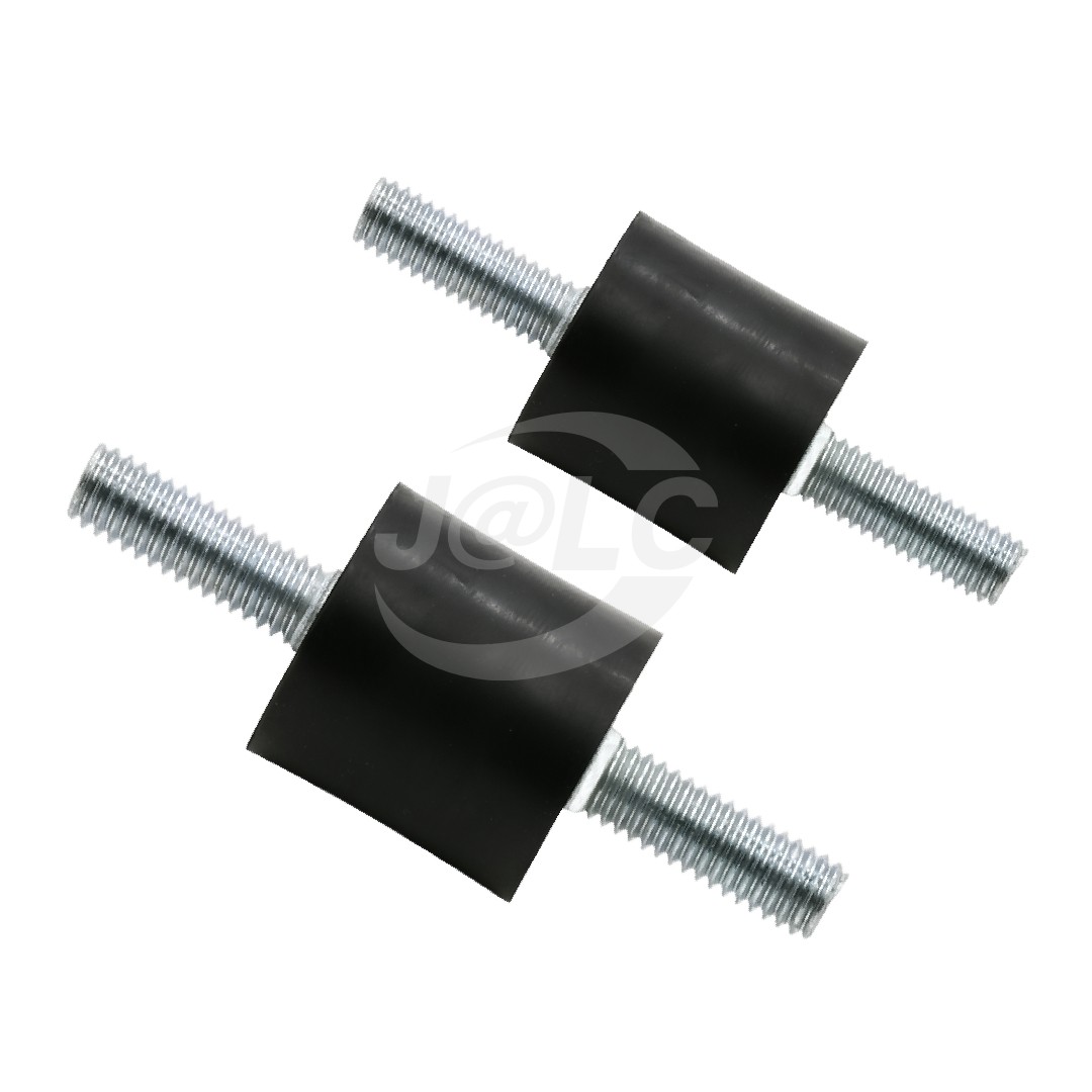
JLCMC HGYE series product image showing cylindrical rubber bodies and threaded metal attachments. Confirm the selected variant's dimensions and loading data.
Trace the Entire Transmission Path
Begin at the vibrating assembly and follow every connection to the stationary structure. The feet are obvious, but they may not be the only links. List rigid pipework, ducting, conduit, cable-tray brackets, guards, tensioned hoses, locating stops and any shipping or assembly restraints.
Rigid bypass paths obey the laws of parallel dynamic stiffness: \(k_{\mathrm{system}}=k_{\mathrm{isolator}}+k_{\mathrm{bypass}}\). If hard conduit, rigid piping, metallic cable trays, or interlocked sheet-metal guards bridge the vibrating chassis to the foundation with stiffness \(k_{\mathrm{bypass}}\gg k_{\mathrm{isolator}}\), the mechanical vibration completely short-circuits the resilient mounts. Under standard isolation troubleshooting criteria (such as ISO 2017 and ASHRAE vibration control standards), all auxiliary connections must incorporate multi-axis flexible braided hoses, 90-degree expansion loops, or isolated hangers. Decoupling the parallel path ensures that compliant motion is governed exclusively by the elastomer's dynamic transfer impedance.
Look for less visible contacts too. A cover can touch a frame only when the equipment is loaded. A hose that was slack during assembly may pull tight after a tank fills or a tray moves. A retained spacer can sit clear at rest but contact the base during startup. Inspect the operating configuration, not just the unloaded assembly on a bench.
Do not remove necessary guards or restraints as a permanent solution. Redesign an interfering connection so it performs its function while allowing the intended movement. The required clearance and restraint arrangement should come from the equipment and mount design.
Match Mount Direction to the Real Load
Compression
In compression, the load acts toward the mounting surface and shortens the rubber element. A vertically supported machine may mainly load its mounts this way, but its center of gravity and external forces can still create unequal reactions. Confirm that the mounting faces are suitably aligned and supported.
Shear
In shear, the load acts parallel to the mounting surface. An assembly mounted against a vertical wall may load the rubber substantially in shear. The same physical part can have different stiffness and load limits in compression and shear. A catalog value for one direction should not be reused for the other.
Tension and combined loads
A mount may experience tension if an assembly lifts, tips or hangs from it. Do not assume a rubber-to-metal bond is an approved lifting or suspension element. If the application can unload or pull on a mount, verify the permitted loading and whether a captive arrangement is necessary.
Real machines often combine vertical weight with lateral forces and moments. Map those loads before choosing the orientation. A diagram showing each force direction is more useful than a note that says only “use four rubber mounts.”
Check Load Distribution and Deflection Together
Estimate the total operating mass, including fluids, tooling and components added after installation. Locate its center of gravity relative to the mount positions. Equal spacing does not guarantee equal loading if a motor, reservoir or tooling package sits at one end.
Then inspect the installed heights under the expected load. Unequal compression can indicate unequal reactions, inconsistent support elevations, different mount variants or a twisted structure. It is an observation to investigate, not an instruction to force every mount to the same height regardless of load.
A simple linear model illustrates why stiffness matters: a supported mass and its effective stiffness determine a natural frequency. Actual rubber can behave nonlinearly and its dynamic response need not match a static estimate. Use the selected mount's available curves or supplier assessment for performance decisions rather than calculating a confident isolation percentage from diameter and hardness alone.
Vibration engineering standards explicitly distinguish static stiffness (\(k_{s}\)) from dynamic stiffness (\(k_{d}\)). For natural rubber compounds, the dynamic-to-static stiffness ratio typically ranges between \(k_{d}/k_{s}\approx 1.2\sim 1.6\), meaning the actual operating natural frequency in service will be \(10\%\sim 25\%\) higher than calculated from simple static deflection alone. Furthermore, the system transmissibility curve reveals that whenever excitation frequency coincides with the natural resonance peak (\(r\approx 1.0\)), transmissibility peaks at \(T_{r}\approx 1/(2\zeta )\approx 5\sim 10\) depending on rubber damping ratio (\(\zeta \approx 0.05\sim 0.10\)). Machine startup, shutdown, and variable-frequency drive ramps must sweep through this critical resonance band quickly to prevent structural fatigue.
Common Bypasses and What to Inspect
| Observation | Possible transmission path | Inspection focus | Corrective direction |
|---|---|---|---|
| Little improvement after installing mounts | Rigid service or bracket bypass | Every connection to the surrounding frame | Provide an appropriate flexible or isolated connection |
| Vibration changes when the machine is fully loaded | Contact closes under deflection | Stops, covers, pipe clearances and loaded heights | Restore the designed movement envelope |
| One corner appears heavily compressed | Unequal support reaction or geometry | Center of gravity, support levels and mount identity | Correct the load/support arrangement |
| Movement is restricted after final tightening | Fastener or washer bridges the compliant element | Cross-section of the bolted joint | Use the intended fastening and isolation details |
| Vibration peaks at a particular speed | System resonance or changing excitation | Frequency and response through the speed range | Review mount stiffness and the source separately |
| New vibration appears after maintenance | Changed routing or a retained assembly restraint | Recently moved hoses, brackets and spacers | Restore the verified installed configuration |
The table lists diagnostic possibilities, not guaranteed fault identifications. Several mechanisms can occur together, and a source problem may remain after a bypass is corrected.
Install Fasteners Without Defeating the Mount
Study a cross-section of the joint. A bolt, sleeve or washer can be essential to retaining an isolator, but it must not unintentionally clamp the equipment directly to the stationary structure. A design with two separate bonded metal ends works differently from a through-bolt passing through a rubber pad. Treat them as different joints.
Use the specified fastening method and torque. Do not choose an arbitrary low torque to make a mount feel softer; inadequate fastening can create a separate looseness problem. Likewise, do not keep tightening a rubber element until visible movement disappears. The intended flexibility is part of the design.
The mounting surfaces should permit the intended contact and alignment. Pulling misaligned parts together with the mount fasteners can preload the rubber sideways or distort the supporting frame. Resolve the geometry in the metal structure before asking the elastomer to accommodate it.
During assembly, avoid applying uncontrolled torsion through the rubber body. Follow the mount supplier's method for restraining and tightening the metal attachments. If a compact installation prevents tool access, revise the bracket arrangement before installation becomes dependent on improvised gripping of the elastomer.
Validate the Installation with Repeatable Observations
Establish a baseline before changing the support. Record operating speed, load state, measurement position and direction. Select measurement quantities that answer the actual question: transmitted acceleration at the support, motion of a sensitive payload or structure-borne noise at a particular location.
A comparison made at a different speed or with a sensor in a different position can be misleading. Use the same mounting method for the measurement sensor and compare equivalent operating intervals. For variable-speed equipment, observe the relevant speed range and transitions rather than one convenient steady condition.
Change one identifiable issue at a time where practical. For example, correcting an unintended guard contact while keeping the mounts unchanged can help separate a bypass problem from a stiffness-selection problem. Keep notes and photographs of the as-tested arrangement so the result can be reproduced after servicing.
Finally, inspect the machine itself. Isolation can reduce what reaches the frame without correcting the source. A damaged bearing, loose assembly or misalignment still requires its own diagnosis. Do not use a quieter surrounding structure as the sole acceptance criterion for machine condition.
Choosing a JLCMC Mount for the Installation
Use JLCMC's Acoustic Insulation and Shockproof category to compare mounting families, then assess the selected model's interfaces and data. For HGYE, the double external-thread arrangement may suit a compact connection where both sides accept threaded attachments. That is a geometry consideration, not proof of suitability for a particular load.
Before final selection, collect the operating mass, support reactions, excitation frequencies, loading directions, available envelope and environmental exposure. Request any missing load-deflection or direction-specific limits. Verify rubber compatibility with actual oils, cleaning agents and temperatures instead of transferring another manufacturer's natural-rubber limits to this series.
FAQ about Rubber Vibration Isolators
Will softer rubber always isolate better?
No. A softer mount may increase motion, affect stability or be unsuitable for the load. Effective isolation depends on the system's frequency response and allowable movement as well as material hardness.
Can I add more mounts to reduce the load on each one?
Adding mounts changes both load distribution and total stiffness. It may reduce each mount's deflection and change the response unfavorably. Reassess the complete arrangement rather than assuming more mounts improve isolation.
Can the same mount be used vertically and horizontally?
Only when the relevant directional loads and stiffness are acceptable. A horizontal installation may introduce shear or tension that differs from the catalog condition you first reviewed.
Does a loose cable count as a bypass?
Its mechanical influence depends on stiffness, routing and tension. A flexible cable loop may accommodate movement, while a tightly bound cable bundle or rigid conduit can restrict it. Inspect the installed bundle throughout the operating motion.
Should a restraint touch the machine during normal operation?
Follow the designed restraint arrangement. Some systems use deliberate clearances so restraints engage only under specified movement. Others have different retention details. Do not change a restraint gap without checking its function.
What is the most useful maintenance record?
Keep the exact mount part numbers, installed orientation, loaded heights, service routing and baseline measurements. Photographs of clearances and connections make unintended changes easier to identify later.
Conclusion: Rubber Vibration Isolation
Rubber vibration isolation depends on the whole installation. Match the mount to the load and excitation, preserve its intended movement, and inspect every parallel connection that could carry vibration around it. Verify the result under repeatable operating conditions, while continuing to address faults at the vibration source.
Popular Articles
Keep Learning
Polyurethane Bumper Energy Calculation: Impact Kinetic Formulas, Stroke & Duty Cycles
Key Takeaways Impact energy depends on contact velocity squared, so a small speed change can materially alter the stopping event. Physical bumper height is not the same as permitted compression or usable stopping distance. Include work from a drive force that continues during compression, plus gravity or rotational effects where applicable. Hardness describes indentation resistance; it is not an energy rating or a complete force-deflection curve. Repeated impacts require a duty assessment as well as a......
Rubber Vibration Isolator Natural Frequency Calculation & Rigid Bypass Troubleshooting Standards
Key Takeaways Trace every mechanical connection between the isolated assembly and its surroundings, including services and guards. Compression, shear and tension are different loading conditions; use the data for the intended direction. A mount must be loaded appropriately, not merely kept below its maximum capacity. Keep deliberate retention hardware compatible with the movement needed for isolation. Compare vibration before and after changes at consistent operating conditions and measurement locatio......
What Is a Torx Screw? Star Drive and Security Torx Explained
If you have seen a screw with a six-point star recess, you have likely seen a Torx screw. So, what is a Torx screw? It is a screw with a six-lobe drive profile. You use a Torx bit to turn the screw. People often call this shape a star drive because of its six-lobe form. The standard Torx profile has six smooth, round lobes rather than sharp points. Other six-lobe drive profiles may look similar, but their dimensions can differ, and their tools may not be interchangeable. This shape gives the tool broa......
How to Drill Out a Stripped Screw Safely?
A stripped screw often turns a simple repair into a hard job. The driver slips because the screw recess no longer gives the bit a firm grip. A broken head or rusted screw creates a similar problem. Drilling screws out should come after simpler removal methods fail. Your goal is to remove enough metal to free the screw head without harm to the part. Good control matters more than force. A drill bit that moves off center might damage the hole or nearby surface. Start with a small bit and keep the drill ......
How to Remove a Stripped Hex Bolt: 7 Effective Removal Methods
A stripped hex bolt loses enough tool contact that a normal hex key or socket slips under force. The damage might affect an internal hex recess or the outer bolt head. Rust can make the problem worse because the thread then needs more force to turn. The safest stripped hex bolt removal method starts with a damage check. Use the least harsh option first, then move to stronger methods only if needed. Your main goal is to remove the bolt without harm to the thread or nearby part. What Is a Stripped Hex B......
Self-Drilling vs Self-Tapping Screws: What Is the Difference?
People often treat self-drilling and self-tapping screws as the same fastener. The two terms have a close link, but they do not mean the same thing. A self-tapping screw forms or cuts its own matching thread as you drive the screw into a suitable base material. Depending on the screw design and material, some self-tapping screws need a pre-drilled pilot hole, while others can be installed directly. A self-drilling screw is a type of self-tapping screw with a drill point at the tip, which drills the ho......