Drill Bit Size Chart: Number, Letter, Fractional & Metric
16 min
- What Are the Four Drill Bit Sizing Systems?
- How to Read This Drill Bit Size Chart
- Fractional Drill Bit Chart
- Number Drill Bit Chart
- Letter Drill Bit Chart
- Metric Drill Bit Sizes
- Drill Bit Lengths: Jobber, Stub, and Long Series
- Numbered Drills vs. Wire Gauges: Related but Not the Same
- Drill Bit Types at a Glance
- FAQ about Drill Bit Size Chart
- About This Drill Bit Size Chart
Key Takeaways
- A drill bit size chart has to cover four systems — fractional (inches), number (#1–#80), letter (A–Z), and metric (mm) — because the same physical diameter can carry three different callouts.
- Number sizes provide intermediate diameters between standard fractional-inch drill sizes, allowing finer selection where 1/64-inch increments are too coarse — which is why a 1/4-20 tap takes a #7 drill (0.201 inch).
- Convert decimal inches to millimeters by multiplying by 25.4; the charts below give both equivalents for every size.
- Number and letter designations are associated with historical wire-gauge numbering systems, but they follow their own standardized diameter series — they size drill bits, while AWG sizes electrical wire. The two are not interchangeable.
- Drill bit length (jobber, stub, long) changes reach and rigidity, not diameter — pick the length from hole depth and setup stiffness, then pick the diameter from the chart.
- All chart values are standard reference sizes; for critical holes, verify the final diameter against the tooling manufacturer's data.
Ask three suppliers for "a 5.1mm drill bit" and you may receive three different answers: a #7, a 0.201-inch jobber drill, or the metric drill itself — all cutting essentially the same hole. That overlap is not confusion in the industry; it is the residue of three sizing systems that grew up separately and never went away. The frustration is real, though, especially when a drawing calls out one system and the drill index in the shop is organized in another.
This drill bit size chart puts all four systems in one place — fractional, number, letter, and metric — with decimal-inch and millimeter equivalents for every size, so any callout can be matched to what is actually on the shelf. It also covers the questions the charts alone do not answer: why number sizes exist, how drill bit lengths differ, and where the number system overlaps with (and differs from) electrical wire gauges.
What Are the Four Drill Bit Sizing Systems?
Inch-system drill bits are sized in three parallel ways, and each system exists for a practical reason:
- Fractional sizes step through 1/64 inch increments from 1/64 up to 1 inch and beyond. They are the oldest and most intuitive system — the fraction is the diameter — but the 1/64 step is too coarse for the small end of the range.
- Number sizes run from #80 (smallest, 0.0135 inch) to #1 (largest, 0.228 inch). They are associated with the wire gauge numbers used for drawing metal wire, and they provide intermediate diameters between the fractional sizes, with steps finer than 1/64 inch.
- Letter sizes run from A (0.234 inch) to Z (0.413 inch), continuing the series above #1 up to 13/32 inch and slightly beyond.
- Metric sizes are simply the diameter in millimeters. Standard sets step 0.5mm apart through the common range, with 0.1mm steps in the smallest sizes.
The systems overlap in coverage rather than replace each other. Between 0.228 inch (#1) and 0.234 inch (letter A) there is no fractional step at all. Between 13/64 inch and 1/4 inch, the standard fractional sizes are 7/32 and 15/64 inch, and number sizes such as #6, #5, #4, and #3 provide additional intermediate diameters. A workshop drawing that says "drill 5.2mm" and a shelf organized in inch sizes are reconciled by the charts below.
How to Read This Drill Bit Size Chart
Every row in this drill bit diameter chart gives the callout size plus its decimal-inch and millimeter equivalents, so the tables work in both directions. The conversion behind them is fixed: 1 inch = 25.4mm exactly, so a #7 drill at 0.201 inch is 5.11mm, and a 6mm drill is 0.2362 inch.
Two reading notes. First, the decimal-inch values for number and letter sizes are the industry's standard reference figures — they are not derived by formula, and a few steps in the number series are closer together than others (the gauge scale descends from wire drawing, not from arithmetic). Second, the millimeter values are rounded to two decimal places for readability. For precision applications, use the unrounded nominal diameter and verify the drill manufacturer's dimensional tolerances and the required finished-hole tolerance.
Fractional Drill Bit Chart
Fractional sizes from 1/64 through 1 inch, with decimal and millimeter equivalents:
| Fractional (in) | Decimal (in) | Metric (mm) |
|---|---|---|
| 1/64 | 0.0156 | 0.40 |
| 1/32 | 0.0313 | 0.79 |
| 3/64 | 0.0469 | 1.19 |
| 1/16 | 0.0625 | 1.59 |
| 5/64 | 0.0781 | 1.98 |
| 3/32 | 0.0938 | 2.38 |
| 7/64 | 0.1094 | 2.78 |
| 1/8 | 0.125 | 3.18 |
| 9/64 | 0.1406 | 3.57 |
| 5/32 | 0.1563 | 3.97 |
| 11/64 | 0.1719 | 4.37 |
| 3/16 | 0.1875 | 4.76 |
| 13/64 | 0.2031 | 5.16 |
| 7/32 | 0.2188 | 5.56 |
| 15/64 | 0.2344 | 5.95 |
| 1/4 | 0.25 | 6.35 |
| 17/64 | 0.2656 | 6.75 |
| 9/32 | 0.2813 | 7.14 |
| 19/64 | 0.2969 | 7.54 |
| 5/16 | 0.3125 | 7.94 |
| 21/64 | 0.3281 | 8.33 |
| 11/32 | 0.3438 | 8.73 |
| 23/64 | 0.3594 | 9.13 |
| 3/8 | 0.375 | 9.53 |
| 25/64 | 0.3906 | 9.92 |
| 13/32 | 0.4063 | 10.32 |
| 27/64 | 0.4219 | 10.72 |
| 7/16 | 0.4375 | 11.11 |
| 29/64 | 0.4531 | 11.51 |
| 15/32 | 0.4688 | 11.91 |
| 31/64 | 0.4844 | 12.30 |
| 1/2 | 0.5 | 12.70 |
| 33/64 | 0.5156 | 13.10 |
| 17/32 | 0.5313 | 13.49 |
| 35/64 | 0.5469 | 13.89 |
| 9/16 | 0.5625 | 14.29 |
| 37/64 | 0.5781 | 14.68 |
| 19/32 | 0.5938 | 15.08 |
| 39/64 | 0.6094 | 15.48 |
| 5/8 | 0.625 | 15.88 |
| 41/64 | 0.6406 | 16.27 |
| 21/32 | 0.6563 | 16.67 |
| 43/64 | 0.6719 | 17.07 |
| 11/16 | 0.6875 | 17.46 |
| 45/64 | 0.7031 | 17.86 |
| 23/32 | 0.7188 | 18.26 |
| 47/64 | 0.7344 | 18.65 |
| 3/4 | 0.75 | 19.05 |
| 49/64 | 0.7656 | 19.45 |
| 25/32 | 0.7813 | 19.84 |
| 51/64 | 0.7969 | 20.24 |
| 13/16 | 0.8125 | 20.64 |
| 53/64 | 0.8281 | 21.03 |
| 27/32 | 0.8438 | 21.43 |
| 55/64 | 0.8594 | 21.83 |
| 7/8 | 0.875 | 22.23 |
| 57/64 | 0.8906 | 22.62 |
| 29/32 | 0.9063 | 23.02 |
| 59/64 | 0.9219 | 23.42 |
| 15/16 | 0.9375 | 23.81 |
| 61/64 | 0.9531 | 24.21 |
| 31/32 | 0.9688 | 24.61 |
| 63/64 | 0.9844 | 25.00 |
| 1 | 1.0 | 25.40 |
Fractional drills are available in larger diameters beyond 1 inch in steps of 1/64 inch or 1/32 inch depending on the manufacturer. The values above are nominal reference sizes; ground and rolled drills of the same nominal size sit within the manufacturer's tolerance band around these figures.
Number Drill Bit Chart
The number drill bit size chart below lists sizes from #1 (largest) down to #80 (smallest):
| Number | Decimal (in) | Metric (mm) |
|---|---|---|
| #1 | 0.228 | 5.79 |
| #2 | 0.221 | 5.61 |
| #3 | 0.213 | 5.41 |
| #4 | 0.209 | 5.31 |
| #5 | 0.2055 | 5.22 |
| #6 | 0.204 | 5.18 |
| #7 | 0.201 | 5.11 |
| #8 | 0.199 | 5.05 |
| #9 | 0.196 | 4.98 |
| #10 | 0.1935 | 4.91 |
| #11 | 0.191 | 4.85 |
| #12 | 0.189 | 4.80 |
| #13 | 0.185 | 4.70 |
| #14 | 0.182 | 4.62 |
| #15 | 0.18 | 4.57 |
| #16 | 0.177 | 4.50 |
| #17 | 0.173 | 4.39 |
| #18 | 0.1695 | 4.31 |
| #19 | 0.166 | 4.22 |
| #20 | 0.161 | 4.09 |
| #21 | 0.159 | 4.04 |
| #22 | 0.157 | 3.99 |
| #23 | 0.154 | 3.91 |
| #24 | 0.152 | 3.86 |
| #25 | 0.1495 | 3.80 |
| #26 | 0.147 | 3.73 |
| #27 | 0.144 | 3.66 |
| #28 | 0.1405 | 3.57 |
| #29 | 0.136 | 3.45 |
| #30 | 0.1285 | 3.26 |
| #31 | 0.12 | 3.05 |
| #32 | 0.116 | 2.95 |
| #33 | 0.113 | 2.87 |
| #34 | 0.111 | 2.82 |
| #35 | 0.11 | 2.79 |
| #36 | 0.1065 | 2.71 |
| #37 | 0.104 | 2.64 |
| #38 | 0.1015 | 2.58 |
| #39 | 0.0995 | 2.53 |
| #40 | 0.098 | 2.49 |
| #41 | 0.096 | 2.44 |
| #42 | 0.0935 | 2.37 |
| #43 | 0.089 | 2.26 |
| #44 | 0.086 | 2.18 |
| #45 | 0.082 | 2.08 |
| #46 | 0.081 | 2.06 |
| #47 | 0.0785 | 1.99 |
| #48 | 0.076 | 1.93 |
| #49 | 0.073 | 1.85 |
| #50 | 0.07 | 1.78 |
| #51 | 0.067 | 1.70 |
| #52 | 0.0635 | 1.61 |
| #53 | 0.0595 | 1.51 |
| #54 | 0.055 | 1.40 |
| #55 | 0.052 | 1.32 |
| #56 | 0.0465 | 1.18 |
| #57 | 0.043 | 1.09 |
| #58 | 0.042 | 1.07 |
| #59 | 0.041 | 1.04 |
| #60 | 0.04 | 1.02 |
| #61 | 0.039 | 0.99 |
| #62 | 0.038 | 0.97 |
| #63 | 0.037 | 0.94 |
| #64 | 0.036 | 0.91 |
| #65 | 0.035 | 0.89 |
| #66 | 0.033 | 0.84 |
| #67 | 0.032 | 0.81 |
| #68 | 0.031 | 0.79 |
| #69 | 0.0292 | 0.74 |
| #70 | 0.028 | 0.71 |
| #71 | 0.026 | 0.66 |
| #72 | 0.025 | 0.64 |
| #73 | 0.024 | 0.61 |
| #74 | 0.0225 | 0.57 |
| #75 | 0.021 | 0.53 |
| #76 | 0.02 | 0.51 |
| #77 | 0.018 | 0.46 |
| #78 | 0.016 | 0.41 |
| #79 | 0.0145 | 0.37 |
| #80 | 0.0135 | 0.34 |
Note that the steps are not uniform: #30 to #31 jumps 0.0085 inch while #36 to #35 moves only 0.0035 inch. That irregularity is inherited from the wire gauge scale, and it is why matching a drill to a hole spec means reading the chart rather than counting steps.
Letter Drill Bit Chart
Letter sizes from A to Z:
| Letter | Decimal (in) | Metric (mm) |
|---|---|---|
| A | 0.234 | 5.94 |
| B | 0.238 | 6.05 |
| C | 0.242 | 6.15 |
| D | 0.246 | 6.25 |
| E | 0.250 | 6.35 |
| F | 0.257 | 6.53 |
| G | 0.261 | 6.63 |
| H | 0.266 | 6.76 |
| I | 0.272 | 6.91 |
| J | 0.277 | 7.04 |
| K | 0.281 | 7.14 |
| L | 0.290 | 7.37 |
| M | 0.295 | 7.49 |
| N | 0.302 | 7.67 |
| O | 0.316 | 8.03 |
| P | 0.323 | 8.20 |
| Q | 0.332 | 8.43 |
| R | 0.339 | 8.61 |
| S | 0.348 | 8.84 |
| T | 0.358 | 9.09 |
| U | 0.368 | 9.35 |
| V | 0.377 | 9.58 |
| W | 0.386 | 9.80 |
| X | 0.397 | 10.08 |
| Y | 0.404 | 10.26 |
| Z | 0.413 | 10.49 |
Letter drills take over where the number series ends (#1 at 0.228 inch) and run just past 13/32 inch. In tapping work they appear constantly: the 3/8-24 tap takes a Q drill, the 5/16-24 takes an I, and the 7/16-14 takes a U. The full thread-to-drill pairings are in our tap drill chart.
Metric Drill Bit Sizes
Common metric drill sizes from 0.5 to 13mm in 0.5mm steps:
| Metric (mm) | Decimal (in) |
|---|---|
| 0.5 | 0.0197 |
| 1.0 | 0.0394 |
| 1.5 | 0.0591 |
| 2.0 | 0.0787 |
| 2.5 | 0.0984 |
| 3.0 | 0.1181 |
| 3.5 | 0.1378 |
| 4.0 | 0.1575 |
| 4.5 | 0.1772 |
| 5.0 | 0.1969 |
| 5.5 | 0.2165 |
| 6.0 | 0.2362 |
| 6.5 | 0.2559 |
| 7.0 | 0.2756 |
| 7.5 | 0.2953 |
| 8.0 | 0.315 |
| 8.5 | 0.3346 |
| 9.0 | 0.3543 |
| 9.5 | 0.374 |
| 10.0 | 0.3937 |
| 10.5 | 0.4134 |
| 11.0 | 0.4331 |
| 11.5 | 0.4528 |
| 12.0 | 0.4724 |
| 12.5 | 0.4921 |
| 13.0 | 0.5118 |
Metric drill sets in the small sizes are finer than this table: 0.1mm steps are standard below 2mm, and 0.25mm steps appear through the 2–3mm range. The 0.5mm table above covers the diameters most sets carry in quantity; for a metric tap drill size such as the 5.0mm drill for an M6 thread, the dedicated tap drill chart lists the pairing directly.
Drill Bit Lengths: Jobber, Stub, and Long Series
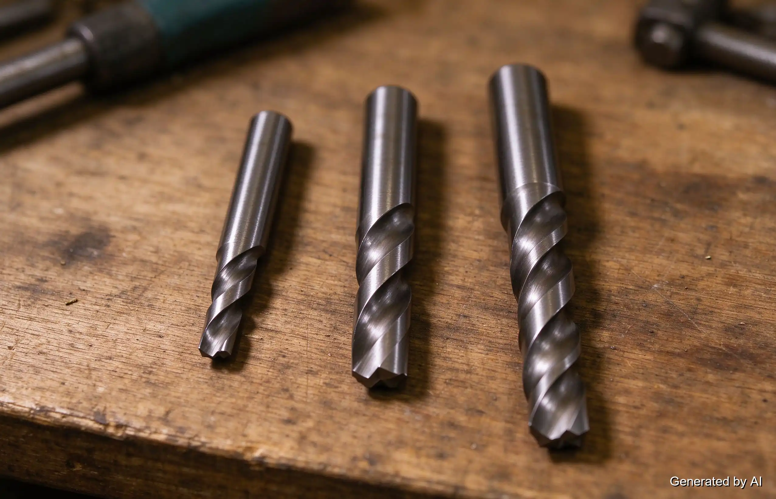
Diameter is only half of a drill bit callout — the other half is length, and choosing it wrong costs as many drills as choosing the diameter wrong. Twist drills come in standardized length series that share the same diameter geometry but differ in flute length and overall reach:
- Jobber length is the default. The flute length runs roughly 9–14 times the diameter, a proportion that balances reach against rigidity for general-purpose holes. Most "assorted drill bit sets" are jobber series.
- Stub (screw-machine) length drills are shorter and notably stiffer. The short flutes resist wandering and deflection, which makes them the choice for drilling on a lathe, in shallow holes, or in hard material where a long drill would flex and snap.
- Long and taper-length drills extend the flute for deep holes and for reaching across clamps and fixtures. The trade-off is rigidity: long drills need lighter feed, careful pecking, and often a pilot hole, or they wander and break.
The failure pattern is familiar: a long drill used where a stub would do flexes in the gap, chips pack in the deep flutes, and the bit snaps at the hole entrance. Length should come from the hole — depth first, then the shortest series that reaches it with clearance for chips and for the drill chuck.
Numbered Drills vs. Wire Gauges: Related but Not the Same
Number drill sizes are associated with historical wire-gauge numbering systems, but they follow their own standardized diameter series. American Wire Gauge (AWG) specifies electrical conductor sizes, whereas number drill designations specify nominal drill diameters. The two systems are not interchangeable: an AWG table sizes the copper conductor inside electrical cable, while a number drill chart sizes cutting tools, and the values in the two tables do not correspond.
The practical caution goes the other way: searching for "12 gauge chart" returns both wire tables and drill charts, and mixing them up produces a hole badly out of spec. When a drawing specifies a numbered drill, size it from the number chart above; when it specifies wire or current capacity, that is an electrical question with its own tables.
Drill Bit Types at a Glance
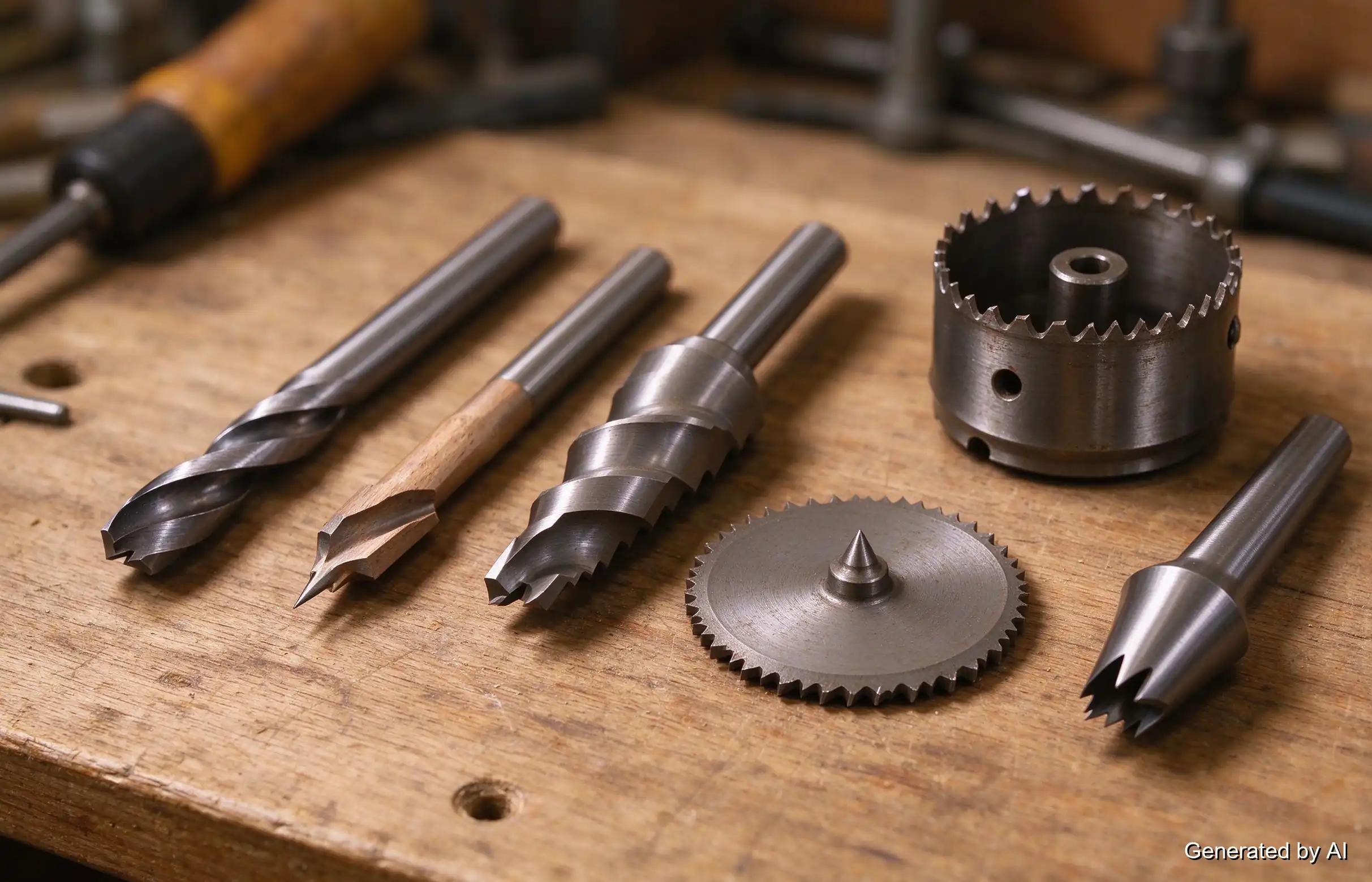
The charts above size the diameter; the tool itself comes in point and flute geometries suited to different work:
| Type | Best suited for | Note |
|---|---|---|
| Twist (general purpose) | Steel, plastics, general bench work | The default; 118° or 135° point depending on material |
| Brad point | Wood, clean entry holes | Center spur prevents walking |
| Step drill | Thin sheet metal, enlarging holes | Multiple diameters on one shank |
| Forstner | Wood, flat-bottomed holes | Bore-quality edges in drilled panels |
| Hole saw | Large diameters in sheet and plate | Cuts an annulus, not the full disc |
| Countersink/center | Chamfers and lathe centers | Finishes hole mouths, not through-boring |
Material choice (HSS versus cobalt versus carbide) changes how each of these performs in hard or abrasive stock, and that selection deserves its own treatment. What the type choice does not change is the diameter: a #7 brad point and a #7 twist drill cut the same 0.201-inch hole. That diameter-first logic carries over to milling, too — JLCMC stocks end mills sized by the same fractional and metric diameters when the work moves from making holes to milling pockets and profiles.
FAQ about Drill Bit Size Chart
Q: What size is a #25 drill bit?
A #25 drill bit measures 0.1495 inch (approximately 3.80mm). Its diameter falls between the standard fractional sizes of 9/64 inch and 5/32 inch.
Q: What is an F size drill bit?
An F drill measures 0.257 inch, or about 6.53mm. It is the conventional tap drill for a 5/16-18 UNC thread, sitting just above the 1/4-inch fractional size that the letter system overlaps.
Q: How do I convert drill bit sizes to millimeters?
Multiply the decimal-inch value by 25.4. A #7 drill at 0.201 inch works out to 5.11mm. The reverse conversion divides millimeters by 25.4. The charts above list both equivalents for every size, so the arithmetic is only needed for sizes not listed.
Q: What drill bit do I use for a 1/4-20 tap?
A #7 drill (0.201 inch, about 5.1mm) is the conventional choice for a 1/4-20 UNC thread. The full pairing of thread sizes to tap drills — UNC, UNF, metric, and NPT — is in our tap drill chart.
Q: Why are there both number and letter drill sizes?
The two systems came from the same wire-gauge lineage but ran out of numbers: the number scale stops at #1 (0.228 inch), and the letter scale A through Z continues the series up to 0.413 inch. Between them they cover the range where 1/64-inch fractional steps are too coarse for tapping and precision fits.
Q: What length drill bit do I need?
Match the length series to the hole: jobber length for general work, stub length for shallow or rigid setups, and long or taper-length series for deep holes. The diameter never changes with length, so pick the diameter from the charts first, then take the shortest length series that reaches the hole depth with room for chips.
About This Drill Bit Size Chart
A drill bit size chart is really four charts wearing one title: fractional for the familiar fractions, number and letter sizes for the fine steps the fractions skip, and metric for drawings already in millimeters. The decimal-inch column is the common language between them, and the 25.4 multiplier is the only conversion worth memorizing.
Diameter is the chart's job; everything else is selection. Length series change reach and rigidity without touching diameter, tool geometry changes how the hole gets cut, and the tap drill pairings connect these sizes to the threads they serve. Once the right hole is drilled, the hardware that goes into it — matched screws and inserts for thin or repairable material — is the same fastening ecosystem our threaded inserts guide covers in depth.
Keep Learning
Drill Bit Size Chart: Number, Letter, Fractional & Metric
Key Takeaways A drill bit size chart has to cover four systems — fractional (inches), number (#1–#80), letter (A–Z), and metric (mm) — because the same physical diameter can carry three different callouts. Number sizes provide intermediate diameters between standard fractional-inch drill sizes, allowing finer selection where 1/64-inch increments are too coarse — which is why a 1/4-20 tap takes a #7 drill (0.201 inch). Convert decimal inches to millimeters by multiplying by 25.4; the charts below give ......
2-Bolt vs. 4-Bolt Flange Bearing Units: Selection Differences That Matter
Key Takeaways Housing geometry and space: A two-bolt flange bearing unit normally uses an oval or diamond-shaped housing, making it ideal when the mounting face is narrow or access is limited. Bolt count vs. capacity: A four-bolt flange bearing unit normally uses a square housing suited for wider interfaces, but bolt count alone does not establish the unit's load capacity. Machine interface priority: Choose the housing pattern based on the machine interface first. Then verify shaft size, published loa......
NPT Thread Guide: Charts, Tap Drill Sizes, and Fitting Identification
Key Takeaways NPT (National Pipe Taper) is a U.S. standard tapered pipe thread defined by ASME B1.20.1: a 60° thread angle and a 1:16 taper on diameter, sealing through thread interference plus sealant. NPT tap drill sizes do not follow the diameter-minus-pitch formula used for straight machine threads — ASME B1.20.1 Appendix B provides guidance, and the tap manufacturer's data decides. The everyday sizes: 1/8 NPT (27 TPI, 0.405 inch major diameter), 1/4 NPT (18 TPI, 0.540 inch), 1/2 NPT (14 TPI, 0.84......
Tap Drill Chart: UNC, UNF, Metric & NPT Drill Sizes
Key Takeaways A tap drill creates the hole a tap cuts internal threads into; the drill diameter controls how much full thread the finished hole has. For Unified inch threads, drill size = major diameter − 1/TPI (rounded to the nearest standard drill) is a commonly used starting point for approximately 75 percent thread engagement; the actual percentage depends on thread geometry and the specified hole tolerance. For metric threads, the quick formula is drill = thread diameter − pitch in millimeters, r......
Comparing Brushless Motors and Stepper Motors: Principles, Structures & Applications
We have many machines around us that have electric motors to operate, including simple tools and complex robots. Brushless DC (BLDC) motors and stepper motors are two popular options for high precision and performance. They are both electrically commutated motors and have no physical brushes, but operate in different ways and are appropriate for different applications. Key Takeaways The advantages of BLDC motors are high-speed, smooth, continuous operation, and high efficiency. Stepper motors can be u......
DC Motor vs. Stepper Motor: What Are They and How Do They Differ?
To clearly distinguish between DC motors and stepper motors, this article uses brushed DC motors as the primary reference for comparison. A brushed DC motor is typically well suited for continuous rotation, high-speed operation, and variable-speed control, while a stepper motor is commonly used for low-speed positioning, indexing, and holding torque at standstill. When combined with an encoder and an appropriate controller, a brushed DC motor can also be used for closed-loop positioning. The right cho......