How to Measure Thread Size: Pitch, TPI & Bolt Threads
14 min
- The Two Numbers That Define a Thread
- Thread Pitch Gauge: The Purpose-Built Tool
- Measuring the Major Diameter with a Caliper
- How to Measure TPI on an Inch Thread
- How to Measure Metric Pitch
- Measuring Without Special Tools
- Metric or Inch? Sorting the System First
- The Thread Checker: The Fast Identification Tool
- Measuring a Whole Bolt: Diameter, Length, and Threads
- Special Cases: Tapered Pipe Threads and Female Threads
- FAQ about How to Measure Thread Size
- About This Thread Measuring Guide
Key Takeaways
- How to measure thread size comes down to two numbers: the major diameter (measured across the thread crests) and the pitch, which is threads per inch (TPI) on inch threads and millimeters between crests on metric threads.
- A thread pitch gauge is the purpose-built tool: fan out the blades, find the one whose teeth mesh with no visible gaps, and read the size stamped on it.
- Measure the major diameter with a caliper across a full thread, away from the chamfered end; the reading narrows the size list before the gauge confirms it.
- Metric and inch threads both use 60° profiles, so sort the system using diameter, pitch, and any gauge markings together rather than one reading alone. M8 and 5/16 inch are the classic trap pair.
- A thread checker (a plate of threaded holes) identifies a fastener in seconds and makes a good shop companion, but it covers only the sizes stamped on the plate.
- For a complete bolt, measure diameter and thread as above, then add the length (from under the head for most head styles) and note the head type separately.
A stripped attempt tells the story: an M8 bolt forced into a 5/16-inch nut starts smoothly, binds two turns in, and ruins both threads, because 8.0mm and 7.94mm look identical but belong to different systems. Almost every fastening mistake of this kind traces back to one thing: nobody measured the thread before reaching for hardware. The good news is that measuring a thread takes two numbers and about a minute.
This guide walks through how to measure thread size the way a machine shop does it: the two numbers that define any thread, the tools that read them (a thread pitch gauge, a caliper, or neither), the quick mental sort between metric and inch systems, and the extras: thread checkers, whole-bolt measurements, and the special cases like pipe threads and nuts.
The Two Numbers That Define a Thread
For common fasteners, the major diameter and pitch are the two key measurements used to identify a thread, and learning how to measure thread size means learning to take both. The thread series, profile, tolerance class, and hand may also be needed to fully define a thread for a particular application:
- Major diameter — the outside diameter of the thread, measured across the crests. This is the number in the name: an M8 thread has a nominal major diameter of 8mm, a 1/4-inch thread of 0.250 inch. Actual measured diameters may read slightly smaller because of manufacturing tolerances and wear.
- Pitch — the distance from one thread crest to the next. Inch systems state it as threads per inch (TPI): a 1/4-20 thread runs 20 threads in one inch. Metric systems state it directly in millimeters: M8×1.25 has crests 1.25mm apart.
Two threads can share a diameter and still be different threads (1/4-20 and 1/4-28, or M8×1.25 and M8×1.0), which is why both numbers are always needed. The measurement order that works best in practice: diameter first, because it narrows the candidate list to a few sizes; pitch second, because it settles the question.
Which Tool for Which Job
The tools stack from crude to precise, and each one covers a different part of the question:
| Tool | Best for | Limits |
|---|---|---|
| Thread pitch gauge | Reading TPI or metric pitch directly, in both systems | A blade can partly seat across systems; cross-check with diameter |
| Caliper | Major diameter, and metric pitch across a ten-interval span | Cannot separate threads that share a diameter (1/4-20 vs 1/4-28) |
| Ruler and count | TPI on inch threads; rough metric spans | Counting error grows as the counted span shrinks |
| Thread checker plate | Fast identification of unknown hardware, bin sorting | Only the sizes on the plate, and a worn plate reads poorly |
| Known-hardware comparison | Confirming a suspect size in seconds | Needs the right label on hand |
| Paper impression | Separating metric from inch when nothing else is available | Rough; cannot resolve 1.0mm from 1.25mm |
Thread Pitch Gauge: The Purpose-Built Tool
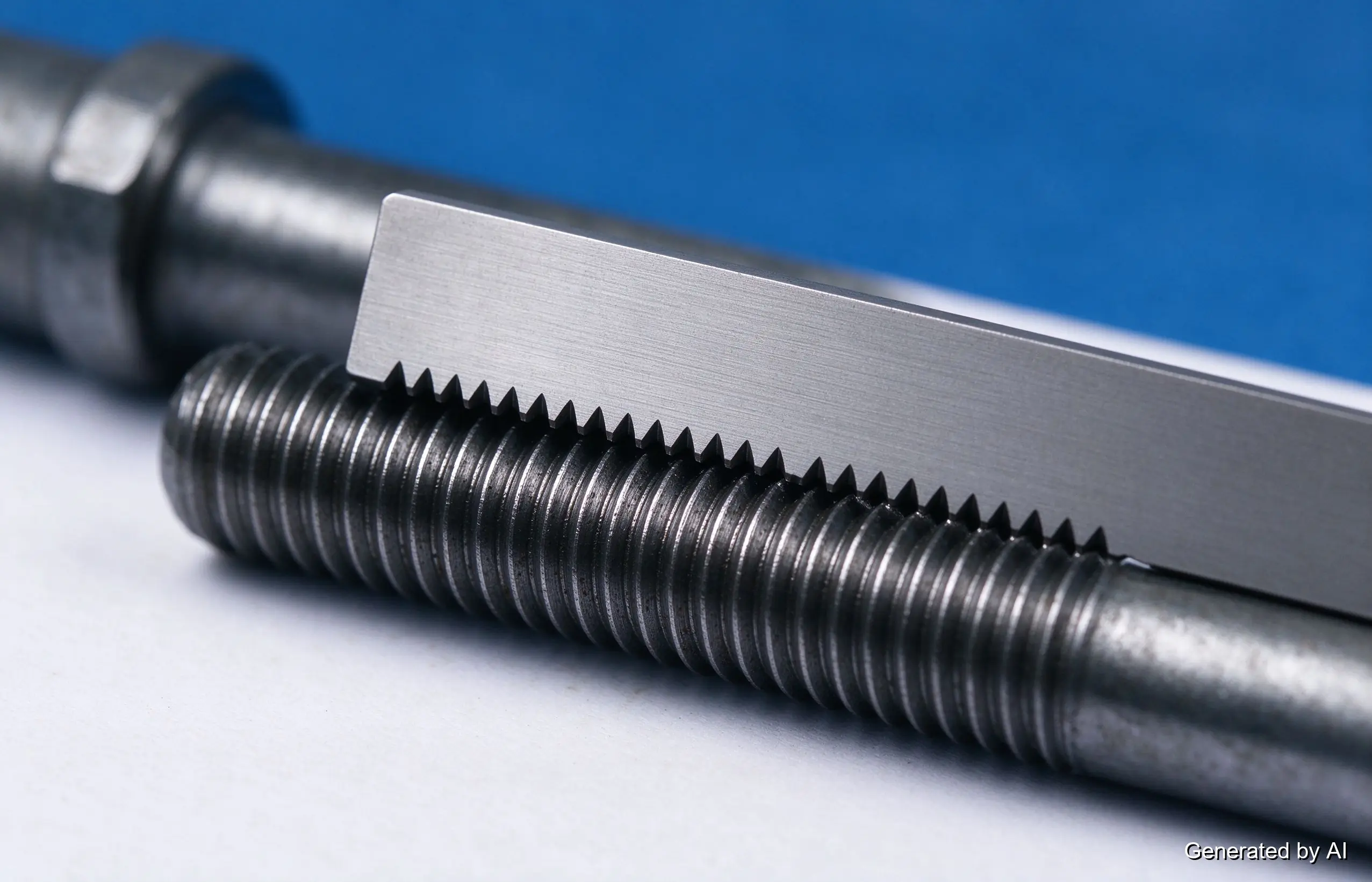
A thread pitch gauge (also written thread gauge, or thread gage in US shop usage) is a folding set of thin steel blades, each cut with teeth at one standard pitch. It is the fastest reliable way to measure thread pitch, and using it takes four steps:
- Clean the thread. Oil and chips make a wrong blade feel almost right.
- Fan the blades and trial-fit. Lay a blade against the thread crest-to-crest along the axis.
- Look for the mesh. The correct blade's teeth seat into the thread valleys with no light showing at any crest; a wrong blade rocks on two points.
- Read the blade. The pitch or TPI is stamped on each blade (metric gauges in millimeters, inch gauges in TPI; combination gauges carry both scales).
One caution keeps the readings honest: metric, UNC, and UNF threads all use the same 60° tooth angle, so a blade can partially seat across systems when the pitches happen to be close. A 1.5mm pitch reads near 16 to 17 TPI on the other scale. The diameter measurement from the next section is the cross-check that catches this.
Measuring the Major Diameter with a Caliper
The diameter measurement is a caliper job, and the technique matters more than the tool's price:
- Measure across the crests of a full thread, taking the largest outside reading.
- Stay away from the chamfered end, where the thread fades out and the reading drops.
- Take the reading at a couple of orientations and accept the largest consistent value; a slightly worn thread measures under its nominal size.
That reading, in millimeters or inches, is the thread's major diameter, the first half of the size. An 8mm reading points to the M8 family, a 0.315-inch reading to the same; a 0.136-inch reading points to a #8 screw rather than any metric size. What the caliper cannot do is separate 1/4-20 from 1/4-28 (both measure 0.250 inch across the crests), and that is exactly what the pitch gauge settles.
How to Measure TPI on an Inch Thread
Inch threads state pitch as threads per inch, and there are two ways to get the number:
- With a gauge: mesh the inch-scale blades as described above and read the stamped TPI directly.
- With a ruler: hold a scale against the thread and count crest peaks within one inch. On small threads, count peaks across half an inch and double it; the longer the counted span, the smaller the counting error.
A 10-32 screw, for example, shows 32 crests per inch; its 10-24 neighbor shows 24 in the same span. The count is the bolt thread pitch, and it is what separates the two, because they share a major diameter (0.190 inch) and feel similar to a fingernail drag.
How to Measure Metric Pitch
Metric threads state pitch as the distance between crests in millimeters, and the direct reading is usually too small to take from a single gap on a small thread. The reliable method measures a span instead:
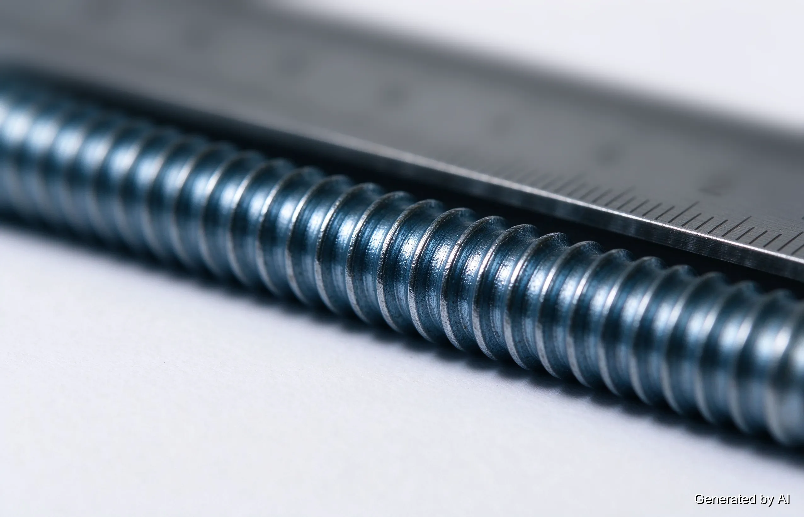
- Press the scale (or the caliper's jaws) against the thread and measure the distance from the first thread crest to the eleventh, covering ten pitch intervals.
- Divide the measured distance by ten. That is the pitch in millimeters.
Measuring ten pitch intervals turns a hard 1.25mm reading into an easy 12.5mm span, and it averages out the small errors of any single gap. An M8×1.25 thread measures 12.5mm from the first crest to the eleventh; an M8×1.0 measures 10.0mm over the same ten intervals. The two fine variants separate cleanly on a span the caliper reads comfortably.
Measuring Without Special Tools
No gauge and no caliper still leaves options for how to measure thread size, with honest limits:
- Ruler and count: the TPI count above works with any ruler marked in inches; the metric equivalent measures a 10-pitch span in millimeters.
- Known-hardware comparison: a box of labeled nuts and bolts is itself a gauge. Find the mate that threads on smoothly over several turns and read its label.
- Paper impression: pressing the thread into a strip of paper transfers a profile whose crest spacing can be measured flat. It is a rough check, good for sorting metric from inch and weak for distinguishing 1.0mm from 1.25mm.
These methods sort systems and confirm obvious sizes well; they do not replace a pitch gauge when the stakes are a tapped hole or a production run. Treat every no-tool reading as provisional until a proper gauge confirms it.
Metric or Inch? Sorting the System First
Before any fine measuring, sort the system. This thirty-second habit prevents the M8/5-16 class of mistakes:
- Pitch-scale hints: metric pitches are stated in round millimeters (1.0, 1.25, 1.5, 2.0…) and inch threads in whole-number TPI (20, 24, 28, 32…) — a useful first hint, not proof on its own.
- Confirm with more than one cue: the major diameter, pitch, thread series, and any gauge or standard markings should agree before you call the size; a single reading can mislead.
- Diameter close calls (M8 at 8mm nominal against 5/16 inch at 7.94mm; M10 against 3/8 inch; M12 against 1/2 inch) differ by fractions of a millimeter, so diameter alone cannot settle the system; pitch and series together do.
Both systems cut the same 60° tooth angle, so nothing about the profile look gives the system away. The full diameter-by-diameter comparison, with the exact near-miss pairs, sits in our metric screw size chart.
The Thread Checker: The Fast Identification Tool
A thread checker (also sold as a nut and bolt thread checker) is a solid plate, usually steel or aluminum, drilled and tapped with a grid of threaded holes in standard sizes, labeled beside each hole. The identification workflow is the simplest of all: try the bolt in the holes until one threads in smoothly over its full length, and read the size off the plate.
Its strengths are speed and durability: no blades to fan, no counting, and it doubles as a sorting station for bins of unidentified hardware. Its limits are just as real. It only knows the sizes stamped on the plate, it reads a size only as well as the holes were cut, and a partial fit on a worn checker can mislead. Professional shops add go/no-go gauges for the opposite kind of certainty (a hardened gauge that must pass on one end and must not on the other), but for bench and repair work, a thread checker plus a pitch gauge covers nearly everything.
Measuring a Whole Bolt: Diameter, Length, and Threads
To measure bolt size as a whole takes three parts, and the thread is only the first. Take them in this order:
- Thread: diameter and pitch, exactly as the sections above.
- Length: measured from the part that seats. Hex and socket-head bolts are measured under the head (the head sits outside the counted material); countersunk and flat-head screws are measured overall, because their heads are meant to end flush. Measuring a hex bolt from the top of its head is the classic length error.
- Head and drive: note the head style (hex, socket, button, countersunk) separately; it changes the driver and the seating, not the thread.
A complete bolt size callout puts thread first (M8×1.25 or 1/4-20), then length (40mm or 1 inch), then head and grade as the drawing requires. Grade markings on the head (the line count on SAE bolts or the number on metric heads) indicate strength class and are worth recording when the bolt will carry load, though reading them correctly is its own topic.
Special Cases: Tapered Pipe Threads and Female Threads
Two threads resist the standard workflow and get their own handling:
- Tapered pipe threads (NPT): the diameter changes along the thread, so a single caliper reading is ambiguous by design. Measure at the first full threads away from the end and expect the reading to map to a nominal pipe size rather than a true diameter; the identification logic and full sizes live in our NPT thread guide.
- Female threads (nuts and tapped holes): there is no crest to reach from outside. Measure the major diameter of a mating male thread (a known bolt that fits), or measure the internal minor diameter with small caliper jaws and look up which size it belongs to. A thread checker plate with male studs does the same job in reverse, and if an internal thread is damaged beyond use, re-cutting it means tapping tools covered in our types of taps guide.
FAQ about How to Measure Thread Size
Q: How do I determine thread size?
Measure the major diameter with a caliper, then measure the pitch with a thread pitch gauge or by counting threads per inch. Sort the system using diameter, pitch, and any gauge markings together rather than one reading alone, and match both numbers against a size chart.
Q: What tool measures thread pitch?
A thread pitch gauge is the purpose-built tool: fan its blades against the thread until one seats with no gaps, and read the pitch or TPI stamped on the blade. A thread checker plate does the same job by trial-fitting the fastener into labeled threaded holes.
Q: How do I measure thread pitch without a gauge?
Count over a known distance: one inch of travel gives TPI directly on inch threads; for metric threads, measure from the first thread crest to the eleventh, covering 10 pitch intervals, then divide the measured distance by 10 to get the pitch in millimeters. A known nut or bolt from a labeled box can also serve as a comparison gauge. Treat these readings as provisional for critical work.
Q: What does thread pitch mean?
Thread pitch is the distance from one thread crest to the next, measured along the thread axis. Metric threads state it in millimeters (M8×1.25 has a 1.25mm pitch); inch threads state the equivalent as threads per inch, so a 1/4-20 has crests every 1/20 inch.
Q: How do I measure an internal thread?
You cannot reach a nut's thread crests from outside, so measure a known male fastener that fits it smoothly and read that bolt's size, or use small caliper jaws on the internal minor diameter and match it to a size table. A thread checker plate with male studs identifies internal threads fastest.
Q: What is a thread checker used for?
A thread checker is a labeled plate of threaded holes used to identify unknown bolts and nuts by trial fit. It is faster than gauges for sorting bins of loose hardware and covers a wide size range in one tool, but it only identifies the sizes it carries.
Q: Why won't my bolt fit the nut?
In order of likelihood: the pitch differs (M8×1.0 versus M8×1.25, or 10-32 versus 10-24), the system differs (M8 versus 5/16 inch), the thread is damaged or dirty, or one part is tapered pipe thread where the other is straight. Measuring both halves, diameter and pitch, settles it in a minute.
About This Thread Measuring Guide
How to measure thread size, in the end, is a two-number discipline: a caliper reading for the major diameter and a gauge or count for the pitch, taken in that order, with the system sorted before the fine measuring starts. The tools stack from a ruler to a pitch gauge to a thread checker, and the job (a one-off repair or a bin of unknown hardware) picks the tool.
The measurement is the first half of the job; the hardware is the second. Once the thread is identified, browse JLCMC's screw range by size and thread to match what you measured, and pair it with the right mating nut. And when a thread is being cut fresh instead of matched, our tap drill chart pairs every size in this guide with the hole that precedes it.
Keep Learning
How to Measure Thread Size: Pitch, TPI & Bolt Threads
Key Takeaways How to measure thread size comes down to two numbers: the major diameter (measured across the thread crests) and the pitch, which is threads per inch (TPI) on inch threads and millimeters between crests on metric threads. A thread pitch gauge is the purpose-built tool: fan out the blades, find the one whose teeth mesh with no visible gaps, and read the size stamped on it. Measure the major diameter with a caliper across a full thread, away from the chamfered end; the reading narrows the ......
Advantages and Disadvantages of Articulated Robots
Introduction Articulated robots offer high flexibility, multi-axis movement, and the ability to handle complex manufacturing tasks, making them suitable for a wide range of automated applications. However, their advantages come with trade-offs, including higher initial investment, programming complexity, maintenance requirements, and safety considerations. Understanding these advantages and disadvantages helps manufacturers determine when articulated robots provide practical value and when other autom......
Types of Taps: A Complete Guide to Tap and Die Types
Key Takeaways Types of taps differ mainly in three ways: where the chips go (spiral point vs spiral flute), how the thread is formed (cut vs form), and how much lead taper the front carries (taper, plug, bottoming). Hand taps come as a three-piece set — taper, plug, and bottoming — distinguished by the length of the chamfered lead, and the right one depends mainly on whether the hole goes through. Spiral point taps push chips forward ahead of the cut and suit through holes; spiral flute taps pull chip......
Metric Screw Size Chart: M1–M24, Pitch & Tap Drill
Key Takeaways The M in an M8 bolt is the major diameter in millimeters: M8×1.25 reads as an 8mm outer diameter with a 1.25mm thread pitch, and coarse pitch is assumed when the pitch is not written. The metric screw size chart below covers the ISO coarse series M1–M24 with pitch, inch equivalents, and the common tap drill for each size. M8 and 5/16 inch sit only 0.06mm apart on diameter, but their thread pitches come from different systems; the two look-alikes must not be mixed in one assembly. Fine pi......
Drill Bit Size Chart: Number, Letter, Fractional & Metric
Key Takeaways A drill bit size chart has to cover four systems — fractional (inches), number (#1–#80), letter (A–Z), and metric (mm) — because the same physical diameter can carry three different callouts. Number sizes provide intermediate diameters between standard fractional-inch drill sizes, allowing finer selection where 1/64-inch increments are too coarse — which is why a 1/4-20 tap takes a #7 drill (0.201 inch). Convert decimal inches to millimeters by multiplying by 25.4; the charts below give ......
2-Bolt vs. 4-Bolt Flange Bearing Units: Selection Differences That Matter
Key Takeaways Housing geometry and space: A two-bolt flange bearing unit normally uses an oval or diamond-shaped housing, making it ideal when the mounting face is narrow or access is limited. Bolt count vs. capacity: A four-bolt flange bearing unit normally uses a square housing suited for wider interfaces, but bolt count alone does not establish the unit's load capacity. Machine interface priority: Choose the housing pattern based on the machine interface first. Then verify shaft size, published loa......