How to Choose a Threaded Standoff for PCB and Mechatronic Assemblies
22 min
- 1. Start with the Function of the Standoff
- 2. Choose the Correct Thread Configuration
- 3. Check the PCB Mounting Interface
- 4. Calculate the Required Standoff Height
- 5. Match the Thread and Check Screw Length
- 6. Select the Material and Surface Finish
- 7. Decide Whether the Joint Should Ground or Insulate
- 8. Evaluate Load, Stiffness and Vibration
- 9. Consider Temperature, Corrosion and the Service Environment
- 10. Check Installation and Maintenance Access
- 11. Apply the Selection Process to the Complete Assembly
- FAQ about Threaded Standoff Selection
Key Takeaways
Select the right configuration: Choose male-female, female-female, or male-male thread configurations based on the two mating interfaces and the intended assembly sequence.
Treat height as a tolerance stack: Standoff body length must satisfy clearance, electrical, thermal, and connector requirements across the full tolerance range, not just the nominal dimension.
Verify thread engagement: Check male thread length against tapped-hole depth and upper screw length against usable female thread depth before approving the hardware.
Match material to the application: Choose metal or plastic according to mechanical load, electrical behavior, thermal limits, corrosion exposure and maintenance frequency.
Do not assume electrical behavior: A metal standoff does not guarantee a reliable ground, and a plastic standoff alone does not guarantee adequate isolation. Verify the complete joint.
Validate the complete assembly: Prototype and test the full joint under realistic assembly, vibration, thermal and service conditions.
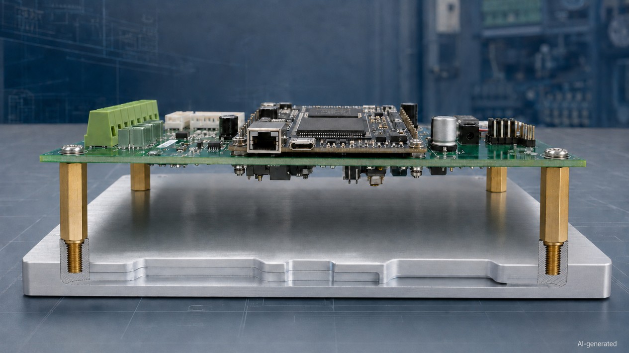
A threaded standoff may be one of the smallest parts in a PCB or mechatronic assembly, but it controls several important relationships at once. It sets the distance between components, supports mechanical loads, affects electrical clearance and determines whether a board can be installed without a wrestling match.
To choose the right threaded standoff, start with the mounting interfaces. Then determine the required body length, match the thread size and engagement, select a suitable material, and verify electrical behavior, vibration resistance, environmental compatibility and tool access.
For a PCB mounted above a tapped metal chassis, a male-female hex standoff is often a practical starting point. It is not a universal answer. A plastic housing, high-voltage board, vibrating sensor module or frequently serviced controller may require a very different solution.
This guide provides a repeatable selection process for PCB mounting, control cabinets, robotics, sensors, instruments and other mechatronic assemblies.
1. Start with the Function of the Standoff
Before opening a product catalog, define what the standoff must do in the finished assembly.
A threaded standoff may perform several functions:
- support a printed circuit board;
- maintain clearance above a chassis or another PCB;
- align a sensor, display or interface board;
- provide a removable threaded mounting point;
- carry compression, tension, shear or bending loads;
- create a conductive path to the chassis;
- isolate a PCB from a conductive enclosure;
- resist vibration and cable forces;
- allow access for inspection or maintenance.
These functions can conflict. For example, a conductive brass standoff may help create a chassis-ground connection, while a nylon standoff is selected specifically to prevent that connection. A tall standoff can improve component clearance but also increases sensitivity to bending and vibration. A large hex body is easy to tighten, yet it may interfere with a connector or a copper keepout area.
Create a short requirement list before selecting the part.
| Requirement | Question to answer |
|---|---|
| Mounting height | What minimum and maximum board-to-base distance can the assembly accept? |
| Interfaces | Does each side have a tapped hole, clearance hole or thin sheet-metal panel? |
| Mechanical load | Will the standoff experience compression, pull-out, shear, bending or vibration? |
| Electrical function | Should it conduct, ground or insulate? |
| Environment | Will it face moisture, chemicals, heat, dust, vacuum or outdoor exposure? |
| Service | How often will the PCB or module be removed? |
| Installation | Can a wrench, socket or screwdriver reach the joint? |
| Space | Is there sufficient room for the body, tool and screw head? |
This first step prevents a common mistake: choosing a standoff that fits the CAD model but not the real assembly process.
2. Choose the Correct Thread Configuration
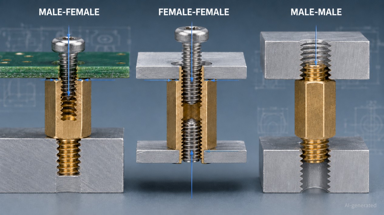
The required thread configuration depends on the mounting features above and below the standoff.
2.1 Male-Female Threaded Standoff
A male-female standoff has an external thread at one end and an internal thread at the other.
It is commonly used when:
- the enclosure or chassis already has a tapped hole;
- the PCB has a clearance hole;
- installation should be completed mainly from the PCB side;
- multiple standoff levels need to be stacked;
- a removable upper component is mounted to a fixed base.
For a PCB above a tapped chassis plate, the male end screws into the chassis and the upper screw passes through the PCB into the female end.
A hex body is usually convenient because it can be held with a wrench while the upper screw is tightened.
2.2 Female-Female Threaded Standoff
A female-female standoff has internal threads at both ends.
It is suitable when:
- both mating parts have clearance holes;
- separate screws can be installed from both sides;
- the base is not tapped;
- the assembly needs removable hardware at both interfaces.
Check whether the internal thread runs through the complete body or consists of two blind threaded holes. With a through-threaded body, screws entering from opposite ends may collide. With blind threads, either screw may bottom out before clamping the assembly.
2.3 Male-Male Threaded Standoff
A male-male standoff has external threads at both ends.
Typical applications include:
- mounting between two tapped components with a suitable assembly sequence;
- extending threaded mounting points;
- positioning brackets or sensor plates;
- creating fixed separation inside a fixture.
Both male thread lengths must be compatible with the mating hole depths. A body that looks symmetrical may still have different thread lengths at each end.
2.4 Self-Clinching and Other Permanently Mounted Standoffs
A thin sheet-metal enclosure may not provide enough thickness for a strong tapped thread. In this case, a self-clinching, swage, weld or press-fit standoff may be more appropriate than a conventional screw-mounted part.
These products require controlled hole dimensions, suitable panel materials and a specified installation process. They should be treated as separate mounting systems, not as interchangeable versions of an ordinary threaded standoff.
| Assembly interface | Common starting configuration |
|---|---|
| Tapped chassis + PCB clearance hole | Male-female |
| Clearance holes on both sides | Female-female |
| Tapped components on both sides | Male-male |
| Thin sheet metal with one-sided access | Self-clinching or another permanently installed style |
| Plastic housing without a durable tapped feature | Molded insert, threaded insert or application-specific mounting feature |
The final choice must also consider assembly order. A mechanically compatible standoff is not useful if the installer cannot reach the lower screw after the enclosure is assembled.
3. Check the PCB Mounting Interface
Selecting a threaded standoff for a PCB requires more than matching the screw diameter to the mounting hole.
Review the following PCB details:
- finished mounting-hole diameter;
- plated or non-plated hole construction;
- PCB thickness and tolerance;
- copper pads and copper keepout areas;
- solder mask around the hole;
- nearby traces, vias and components;
- available washer and screw-head space;
- edge distance;
- support locations;
- board flex during installation.
The current IPC-2221C standard establishes generic printed-board design requirements and includes printed-board mounting holes within its scope. The applicable PCB drawing and product requirements should define the actual hole, conductor clearance and mechanical tolerances.
Mounting-Hole Fit
The hole must provide suitable clearance for the screw without allowing excessive board movement. A hole that is too tight can create assembly difficulty or edge damage. A hole that is unnecessarily large may reduce positioning accuracy and supporting area.
Design Tip
Do not use the nominal thread diameter as the finished PCB hole diameter without checking the required clearance and manufacturing tolerance.
Supporting Face
The upper face of the standoff should support the PCB without contacting nearby components, solder joints or exposed conductors.
Check:
- body diameter or width across flats;
- washer outside diameter;
- screw-head diameter;
- copper and component clearance around the mounting hole.
A wider supporting face can distribute load, but it also occupies more board area. The PCB layout and mechanical design should agree on this interface before the board is released.
Board Distortion
All standoffs supporting one PCB should provide compatible body heights. Unequal heights, an uneven chassis or debris beneath one support can bend the board as the screws are tightened.
Large or irregular boards may require additional support points, particularly near:
- heavy transformers;
- power modules;
- large connectors;
- user-operated switches;
- cable headers;
- components exposed to insertion or removal forces.
More standoffs are not automatically better. Poorly positioned supports can over-constrain the PCB and make tolerance-related distortion worse.
4. Calculate the Required Standoff Height
Standoff height normally refers to the body length between its two supporting faces. A projecting male thread is usually excluded.
The selected height must satisfy several requirements:
- clearance for components and solder joints beneath the PCB;
- clearance above chassis ribs, bosses and fasteners;
- connector mating and latch movement;
- cable routing and bend radius;
- airflow and cooling;
- access for probes or tools;
- electrical clearance;
- PCB deflection;
- manufacturing and assembly tolerances.
A useful starting relationship is:
Required standoff body length ≥ maximum component/solder protrusion below the PCB + tolerance allowance + required clearance
In a more complete evaluation, the selected height should satisfy the largest of the following requirements:
- mechanical clearance;
- electrical clearance;
- thermal or airflow clearance;
- connector and cable clearance;
- service-access clearance.
Illustrative Height Calculation
Suppose the tallest feature beneath a PCB extends 6.2 mm below the board surface. The design also needs:
- 0.5 mm for component and solder variation;
- 0.5 mm for chassis and mounting tolerance;
- 1.0 mm of additional mechanical clearance.
The preliminary requirement is:
6.2 + 0.5 + 0.5 + 1.0 = 8.2 mm
A standard 9 mm or 10 mm standoff may appear suitable, depending on available sizes and the remaining system requirements.
This example is only a geometric calculation. The designer must still check electrical spacing, airflow, connector access, vibration and enclosure height.
Watch Both Ends of the Tolerance Stack
A standoff must prevent interference at the minimum assembled height while avoiding enclosure or connector problems at the maximum height.
Consider:
- minimum and maximum standoff body length;
- PCB thickness tolerance;
- chassis flatness;
- coating thickness;
- component-height tolerance;
- washer thickness;
- deflection under clamp load;
- accumulated variation across multiple mounting points.
Selecting the next taller catalog size is not always a safe shortcut. Extra height can interfere with an upper enclosure panel or increase lateral flexibility.
5. Match the Thread and Check Screw Length
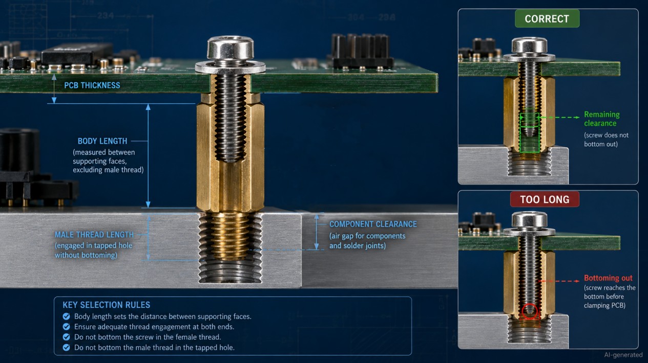
The thread designation must match every mating component exactly.
For metric hardware, M3 x 0.5 indicates:
- 3 mm nominal major diameter;
- 0.5 mm thread pitch.
The ASME B1.13M standard covers general metric M-profile screw threads, including diameter-pitch combinations and tolerance systems.
Imperial PCB hardware may use threads such as #2-56, #4-40 or #6-32. Similar-looking metric and inch threads are not interchangeable. An M3 screw may begin to enter some inch-threaded hardware, but "it started turning" is not a thread specification.
Check:
- metric or inch system;
- nominal thread diameter;
- pitch or threads per inch;
- internal and external thread sizes;
- thread tolerance where specified;
- male thread length;
- usable female thread depth;
- tapped-hole depth;
- screw length;
- mating material.
Check Male Thread Length
The projecting thread on a male-female or male-male standoff must:
- provide adequate engagement;
- avoid bottoming in a blind tapped hole;
- avoid projecting into a restricted area;
- clamp against the correct supporting face;
- remain compatible across the tolerance stack.
Important
Do not assume that a longer male thread produces a stronger joint. Once it bottoms out, the standoff may stop turning before its body seats against the base.
Calculate Upper Screw Length
For a screw passing through a PCB into a female standoff, a simplified starting relationship is:
Screw length = PCB thickness + washer thickness + intended thread penetration
If another plate, bracket or insulating washer is included, add its thickness as well.
The screw must clamp the PCB before reaching the bottom of the female thread. Therefore:
Actual penetration < usable female thread depth
Usable depth may be shorter than the visible hole depth because of thread runout or an unthreaded section at the bottom.
There is no universal thread-engagement rule suitable for every standoff. Required engagement depends on thread size, standoff material, mating material, load, installation cycles and manufacturing tolerance. Use the supplier drawing, application data or an engineering joint calculation.
6. Select the Material and Surface Finish
Material selection affects mechanical strength, thread durability, weight, corrosion resistance, electrical behavior and long-term dimensional stability.
Brass
Brass is a common choice for PCB standoffs because it can be machined accurately and provides durable internal and external threads. Nickel-plated brass is widely used where appearance and corrosion resistance matter.
If the standoff is intended to provide grounding, confirm that the finish and contact surfaces produce the required electrical continuity.
Stainless Steel
Stainless steel is suitable for higher loads, repeated servicing and corrosive environments. It is heavier and generally more expensive than brass or aluminum.
Stainless mating threads may be vulnerable to galling, particularly when installed at high speed or without a suitable joint design.
Plated Carbon Steel
Carbon steel offers useful strength at a practical cost. Its corrosion performance depends heavily on the plating system and whether that coating remains intact after installation and servicing.
Aluminum
Aluminum can reduce the weight of portable or moving equipment. Its threads may be less resistant to repeated installation than harder steel threads, and contact with dissimilar metals should be evaluated in wet or corrosive environments.
Nylon and Other Plastics
Plastic standoffs can provide electrical isolation and low weight, but their performance depends on the exact resin grade.
Evaluate:
- continuous operating temperature;
- short-term temperature peaks;
- moisture exposure;
- chemical compatibility;
- creep under sustained load;
- flammability requirements;
- thread wear during maintenance;
- dimensional stability.
A nylon standoff that works well in a small indoor controller may be unsuitable near a motor, heater or high-load connector.
| Material | Advantages | Limitations to evaluate | Typical use |
|---|---|---|---|
| Brass | Good machinability, reliable threads and electrical conductivity | Higher weight and lower strength than many steels | PCB mounting, instruments and electronic enclosures |
| Stainless steel | High strength and corrosion resistance | Cost, weight and possible thread galling | Industrial, outdoor and corrosive assemblies |
| Plated carbon steel | Good strength, wear resistance and cost efficiency | Coating damage and environmental corrosion | Machinery, fixtures and control equipment |
| Aluminum | Low weight and good machinability | Thread wear and galvanic compatibility | Portable equipment and lightweight assemblies |
| Nylon or engineering plastic | Electrical insulation, low weight and corrosion resistance | Creep, moisture, temperature and lower stiffness | Light-load and electrically isolated PCB assemblies |
7. Decide Whether the Joint Should Ground or Insulate
Electrical behavior should be intentional.
Using a Metal Standoff for Grounding
A metal standoff can form part of a chassis-ground path, but conductivity depends on the complete joint, including:
- standoff material and finish;
- screw and washer material;
- PCB pad design;
- panel paint or anodizing;
- oxide and contamination;
- contact pressure;
- corrosion over time.
A conductive base material does not guarantee a low-resistance connection after plating, painting and assembly.
If grounding is required:
- Define the intended current path.
- Specify the required PCB pad and contact surfaces.
- Confirm compatible finishes and hardware.
- Inspect the assembled contact.
- Measure continuity or resistance.
- Validate performance after environmental and vibration testing.
The standoff should not become an accidental protective-earth connection unless the complete joint is designed and qualified for that function.
Using a Plastic Standoff for Isolation
A plastic standoff can interrupt a conductive mounting path, but the rest of the hardware must also be considered.
A metal screw may still connect the PCB to the chassis through:
- a plated mounting hole;
- a metal washer;
- another mounting point;
- an EMI shield;
- a connector shell;
- a cable ground.
For higher-voltage equipment, insulation design must account for working voltage, impulse voltage, pollution degree, material properties, altitude and the applicable product standard. IEC 60664-1:2020+AMD1:2025 provides requirements for determining clearance, creepage distance and solid insulation in low-voltage systems.
Warning
Standoff body length alone should not be treated as the creepage or clearance distance. The shortest path may run around a screw head, washer, board edge or nearby conductive feature.
8. Evaluate Load, Stiffness and Vibration
A PCB standoff rarely carries only a neat axial compression load. Mechatronic assemblies introduce cable forces, connector insertion loads, machine vibration and acceleration from moving axes.
Possible loads include:
- axial compression from screw tightening;
- tensile or pull-out load;
- lateral shear;
- bending from an offset mass;
- shock;
- cyclic vibration;
- cable pull;
- forces created by plugging and unplugging connectors.
Standoff Height and Bending
A tall standoff is generally more sensitive to lateral deflection and bending than a short standoff with the same body size and material.
When the PCB carries a heavy component or is installed in moving equipment, evaluate:
- standoff length;
- body diameter or width across flats;
- thread size;
- material stiffness;
- distance between support points;
- location of the assembly's center of mass;
- direction of acceleration;
- cable restraint.
Moving one support point closer to a heavy connector may be more effective than simply changing every standoff to a stronger material.
Vibration Retention
Correct tightening and thread engagement are the starting point. Where additional retention is needed, possible methods include:
- compatible threadlocker;
- locking screws;
- prevailing-torque features;
- suitable locking washers;
- mechanical locking features;
- captive hardware.
The method must be compatible with the standoff material, finish, temperature, electrical requirements and maintenance plan.
Caution
Some threadlockers may affect plastics or make future servicing difficult. Locking washers can also damage soft materials or PCB surfaces if used without a suitable interface. Validate the complete method rather than adding a locking product at the end of the design process.
Avoid PCB Over-Clamping
Excessive tightening can:
- crack or delaminate the PCB;
- damage plated mounting holes;
- distort the board;
- crush plastic washers;
- strip female threads;
- create inconsistent stress around components.
Use manufacturer data or a torque established for the actual combination of screw, standoff, washer, PCB and base material. A generic fastener torque table may not protect a delicate PCB.
9. Consider Temperature, Corrosion and the Service Environment
The standoff must maintain its function throughout the expected operating environment.
Temperature
Temperature can affect:
- material strength;
- plastic creep;
- differential thermal expansion;
- thread retention;
- PCB stress;
- coating performance;
- connector alignment.
A metal chassis, PCB laminate and plastic standoff expand at different rates. In an assembly with large temperature swings, rigidly constraining every mounting point may introduce board stress.
Corrosion
Check the combination of:
- standoff material;
- screw material;
- chassis material;
- washers;
- plating;
- humidity;
- condensation;
- salt or chemical exposure.
Dissimilar metals may create galvanic-corrosion risk when an electrolyte such as moisture is present. The solution may involve compatible materials, appropriate finishes, isolation or environmental protection.
Cleanliness and Special Environments
Vacuum, laboratory, semiconductor and clean-process equipment may impose additional requirements for:
- outgassing;
- particle generation;
- lubricant restrictions;
- surface cleanliness;
- coating compatibility;
- traceability.
Food-processing, outdoor and washdown equipment may require corrosion-resistant materials and designs that do not trap contaminants.
Do not select a material from its broad name alone. "Stainless steel" and "engineering plastic" describe families of materials, not a complete performance specification.
10. Check Installation and Maintenance Access
A well-selected standoff should make assembly predictable and servicing reasonably painless.
Review the installation sequence:
- Which side is assembled first?
- Can the standoff be held while the screw is tightened?
- Is there room for a wrench or socket around the body?
- Can the screw be started by hand?
- Will nearby components block the tool?
- Can the PCB be removed without dismantling unrelated modules?
- Is loose hardware likely to fall into the enclosure?
- Can the joint be inspected after assembly?
Hex vs Round Body
A hex standoff is generally easier to hold with a wrench and is a practical choice for serviceable industrial equipment.
A round standoff occupies less radial space and may offer a cleaner appearance. However, it should include an appropriate drive feature if controlled tightening is required.
Design Tip
When checking packaging space, use the hex width across corners rather than only the width across flats. A standoff can clear a nearby component in a static CAD section and still collide with it while being rotated.
Repeated Servicing
If the board will be removed frequently, consider:
- thread-wear resistance;
- captive screws;
- replaceable hardware;
- protection against cross-threading;
- clear tool access;
- consistent tightening procedures;
- whether threadlocker is appropriate.
Start each screw by hand. If it binds immediately, stop and check the alignment. Cross-threading does not improve with confidence.
11. Apply the Selection Process to the Complete Assembly
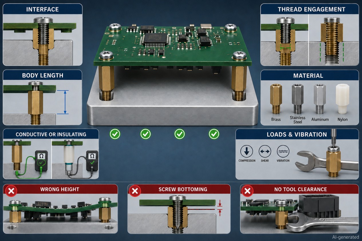
A structured selection process reduces the chance of missing a small but important constraint.
Step-by-Step Selection Workflow
-
Define Requirements
Define the required spacing, support and electrical function.
-
Identify Mounting Features
Identify the mounting feature at each end.
-
Select Configuration
Select male-female, female-female, male-male or another mounting style.
-
Confirm Thread Spec
Confirm the thread system, diameter and pitch.
-
Calculate Body Length
Calculate the required body length from the complete tolerance stack.
-
Check Thread Depths
Check male thread length and female usable thread depth.
-
Calculate Screw Length
Calculate the mating screw length.
-
Select Body Shape
Select the body shape and confirm tool clearance.
-
Choose Material
Choose the material and finish.
-
Evaluate Electrical Behavior
Evaluate grounding, isolation and electrical spacing.
-
Check Mechanical Loads
Check static load, vibration, cable forces and thermal conditions.
-
Prototype and Validate
Prototype and validate the completed assembly.
Worked Example: PCB Mounted in a Metal Controller
Consider a control PCB mounted above a tapped aluminum chassis.
The initial requirements are:
- 10 mm nominal PCB-to-chassis spacing;
- M3 tapped holes in the base;
- clearance holes in the PCB;
- access from the PCB side;
- periodic board replacement;
- conductive connection to chassis at selected mounting points;
- moderate machine vibration.
A reasonable candidate is an M3 male-female hex standoff with a 10 mm body length in a suitable metal.
Before approving the part, the designer should verify:
- M3 pitch and tapped-hole tolerance;
- male thread length against chassis hole depth;
- female thread depth against the upper screw length;
- PCB hole and copper-pad design;
- supporting-face diameter;
- wrench clearance;
- board flatness across all standoffs;
- electrical continuity through the selected finish;
- retention under vibration;
- enclosure clearance above the PCB.
The catalog filter narrows the options. These checks determine whether the selected part actually works.
Final Selection Checklist
| Selection item | Approval question |
|---|---|
| Function | Is the required spacing, support, grounding or isolation clearly defined? |
| Configuration | Do both standoff ends match the assembly interfaces? |
| Thread | Are the system, diameter and pitch correct? |
| Body length | Does the height work across the full tolerance range? |
| Male thread | Is engagement sufficient without bottoming? |
| Female thread | Will the screw clamp before reaching the end? |
| PCB interface | Are the hole, pad, keepout and support area suitable? |
| Body shape | Is there enough room for the body and installation tool? |
| Material | Are strength, stiffness, weight and thread durability adequate? |
| Finish | Is it compatible with corrosion and electrical requirements? |
| Electrical behavior | Has grounding or isolation been verified in the complete joint? |
| Load | Can the assembly withstand compression, shear, bending and cable forces? |
| Vibration | Is the retention method validated? |
| Environment | Are temperature, moisture and chemicals addressed? |
| Maintenance | Can the board be removed and reinstalled safely? |
| Validation | Has the actual assembly been inspected and tested? |
FAQ about Threaded Standoff Selection
Q: What type of threaded standoff is commonly used for PCB mounting?
A male-female hex standoff is commonly used when the chassis has a tapped hole and a screw passes through the PCB from above. Female-female standoffs are useful when separate screws can be installed from both sides.
Q: Is M3 the standard thread size for PCB standoffs?
M3 is common, but it is not universal. Smaller boards may use M2 or M2.5 hardware, while larger or more heavily loaded assemblies may use larger threads. The thread must match the PCB hole, base feature, load and available space.
Q: How is threaded standoff height measured?
Height normally means the body length between the two supporting faces. A projecting male thread is generally excluded. Always confirm the dimensional drawing because catalog terminology can vary.
Q: How do I choose the correct screw length?
Add the PCB thickness, washer thickness and required thread penetration. Confirm that the screw clamps the board before reaching the end of the usable female thread.
Q: Is brass or nylon better for a PCB standoff?
Brass offers durable threads, useful strength and electrical conductivity. Nylon provides insulation and low weight but has lower stiffness and greater sensitivity to creep, moisture and temperature. The better choice depends on the assembly requirements.
Q: Can a metal standoff ground a PCB?
Yes, but only when the complete connection is designed for conductivity. Plating, anodizing, paint, washers, PCB pads and contamination can interrupt the current path. Test the completed assembly.
Conclusion: How to Choose a Threaded Standoff
Choosing a threaded standoff for a PCB or mechatronic assembly is a matter of matching interfaces, dimensions and operating conditions.
Begin with the mounting architecture. Select the correct thread configuration, calculate the body length from the complete stack-up and check every male and female thread against the available engagement. Then evaluate material, grounding or isolation, mechanical load, vibration, temperature, corrosion and maintenance access.
A well-chosen standoff supports the board, protects the surrounding components and makes assembly straightforward. A poorly chosen one tends to reveal itself later, usually as a bottomed screw, a warped PCB or an enclosure lid that misses closing.
For available materials, thread sizes and body lengths, explore the threaded standoff selection at JLCMC.
Popular Articles
Keep Learning
Threaded Standoff vs Spacer: What Is the Difference?
Key Takeaways Threaded standoffs provide both spacing and threaded attachment points, making them ideal for modular assemblies and PCBs. Spacers are unthreaded sleeves that work with through-bolts to maintain gaps in clamped assemblies, offering a simpler and more economical solution. The right choice depends on the load path, assembly sequence, material, and service environment - not just appearance or catalog naming. A threaded standoff and a spacer can look almost identical on a workbench. Both cre......
How to Choose a Threaded Standoff for PCB and Mechatronic Assemblies
Key Takeaways Select the right configuration: Choose male-female, female-female, or male-male thread configurations based on the two mating interfaces and the intended assembly sequence. Treat height as a tolerance stack: Standoff body length must satisfy clearance, electrical, thermal, and connector requirements across the full tolerance range, not just the nominal dimension. Verify thread engagement: Check male thread length against tapped-hole depth and upper screw length against usable female thre......
Threaded Standoff Guide: Types, Sizes, Materials and Applications
Key Takeaways Thread configuration first: Choose female-female, male-female or male-male based on how both sides of the assembly attach — thread config is the most practical way to classify a threaded standoff. Body length is the critical dimension: Standoff length refers to the distance between supporting faces, not total physical length. Reading the wrong length causes incorrect mounting height or screw bottoming. Material affects more than strength: Brass, stainless steel, carbon steel, aluminum an......
Ball Nose End Mill Stepover: Scallop Height and Effective Diameter
Key Takeaways Geometric Control: Stepover directly controls geometric scallop height, but it does not automatically guarantee a measured Ra value. Cusp Height Formula: For a ball radius $R$ and pass spacing $s$ on a flat surface, the ideal cusp height is $h = R - \sqrt{R^2 - \frac{s^2}{4}}$. Tool Radius Advantage: A larger ball can use wider spacing for the same ideal cusp, provided it can reach the required geometry without gouging. Effective Diameter: The active cutting diameter near the tool tip ca......
Manual SMT Stencil Printer Sizing: Print Area, PCB Support and Frame Fit
Key Takeaways Different dimensions: Worktable size, effective print area, board envelope, and stencil frame size are different dimensions. Check the full pattern: Check the whole aperture pattern in its intended orientation, including clearance for the printing stroke. Thickness is not enough: A compatible board thickness does not prove that a populated underside or a support fixture will fit. Support and contact: Stable support and close stencil-to-board contact are necessary for a repeatable printin......
Blind Rivet Guide: Types, Sizes, Uses, Installation and Removal
A blind rivet may be small, but choosing one correctly involves more than matching a rivet to the nearest drill bit. The diameter, grip range, hole size, body material, mandrel material, head style and installation tool all influence the finished joint. A rivet that looks perfectly acceptable before installation can still spin, loosen, pull through the sheet or form incorrectly on the blind side if one of these factors is overlooked. Blind rivets are widely used in sheet-metal fabrication, electrical ......