Indexing Plunger Selection Guide: Engagement Depth, Reset Mechanism, and Load Paths
10 min
- Understand the Two Operating Choices
- Read the Product's Function Field Carefully
- Draw the Engaged and Retracted Positions
- Follow the Load Beyond the Spring
- Compare the Choices by the Required Behavior
- Install for Alignment and Service Access
- Commission the Complete Positioning Cycle
- FAQ about Indexing Plunger Selection
Key Takeaways
- Reset behavior and retention in the retracted position describe operation, not the pin's load capacity.
- Confirm engagement at the receiving feature rather than relying only on the knob position.
- Check the minimum available straight engagement after mounting gaps and lead-in geometry are included.
- Spring force acts along the pin; transverse holding loads also involve the pin, guide, mounting structure and receiving hole.
- Reduce unnecessary unsupported distance and assess bending where the pin bridges a gap.
- Commission every intended position with representative loading and a controlled release procedure.
An adjustment knob returns to its normal position, but the machine's sliding guide still moves. The pin may be sitting against the edge of a hole, touching only its entrance chamfer, or held back by side load. Knob movement alone does not establish useful engagement.
An indexing plunger needs to perform two separate jobs: retract far enough for adjustment, then enter the receiving feature far enough to provide the intended location. When engineering precision stops, guide rails, and height adjusters using components from the JLCMC indexing plungers catalog, the plunger's operating action, installation stack, and structural load path must work in complete agreement. This selection guide explains how to calculate and verify that combination for reliable mechanical positioning.
Understand the Two Operating Choices
Spring return for repeated indexing
A common reset arrangement extends the pin when the operator releases the knob. This suits an adjustment that should return to an indexed position after each movement. The spring provides the extending action; alignment and freedom of movement determine whether the pin can actually enter the hole.
Imagine an adjustable guide with several positioning holes. If the guide stops between holes, a released pin may press against its surface. It will only enter when the features align and the mechanism can travel freely. The application must make the difference between “released” and “engaged” clear to the operator.
Retraction retention for longer adjustments
A rest-position arrangement can hold the pin withdrawn while the assembly moves past several positions. It removes the need to keep pulling the knob throughout that adjustment, but creates an additional step: the operator must release the retained state before engagement can occur.
Standard mechanical positioning and lock-out mechanisms (conforming to general industrial fixture principles such as DIN/ISO indexing guidelines) provide a 90° or 120° rest position that holds the plunger retracted. Pulling the knob and rotating it engages a precision detent notch on the housing, keeping the pin retracted without continuous manual effort. Different indexing mechanisms may use varied detent angles or release mechanisms, so confirm the actual operating sequence on the component engineering drawings.
Terms such as “self-locking” need particular care. Determine which state is retained and what action releases it. The name alone does not prove that an extended pin is positively locked against withdrawal or that the device provides a safety function.
Read the Product's Function Field Carefully
JLCMC lists FWPM Index Pins with Reset Type in the Reset/Self-Locking specification field. The family is identified as a standard index plunger with an A2017 knob and fine thread. Although the page title includes both reset and self-locking terminology, the specification field identifies the listed family as reset.
The separate FWPN indexing pin family lists Self-Locking Type, also with an A2017 knob and fine thread. Use the selected part's instructions or a sample to confirm its retained state and release action. Do not transfer another manufacturer's turning angle or retention mechanism to FWPN.
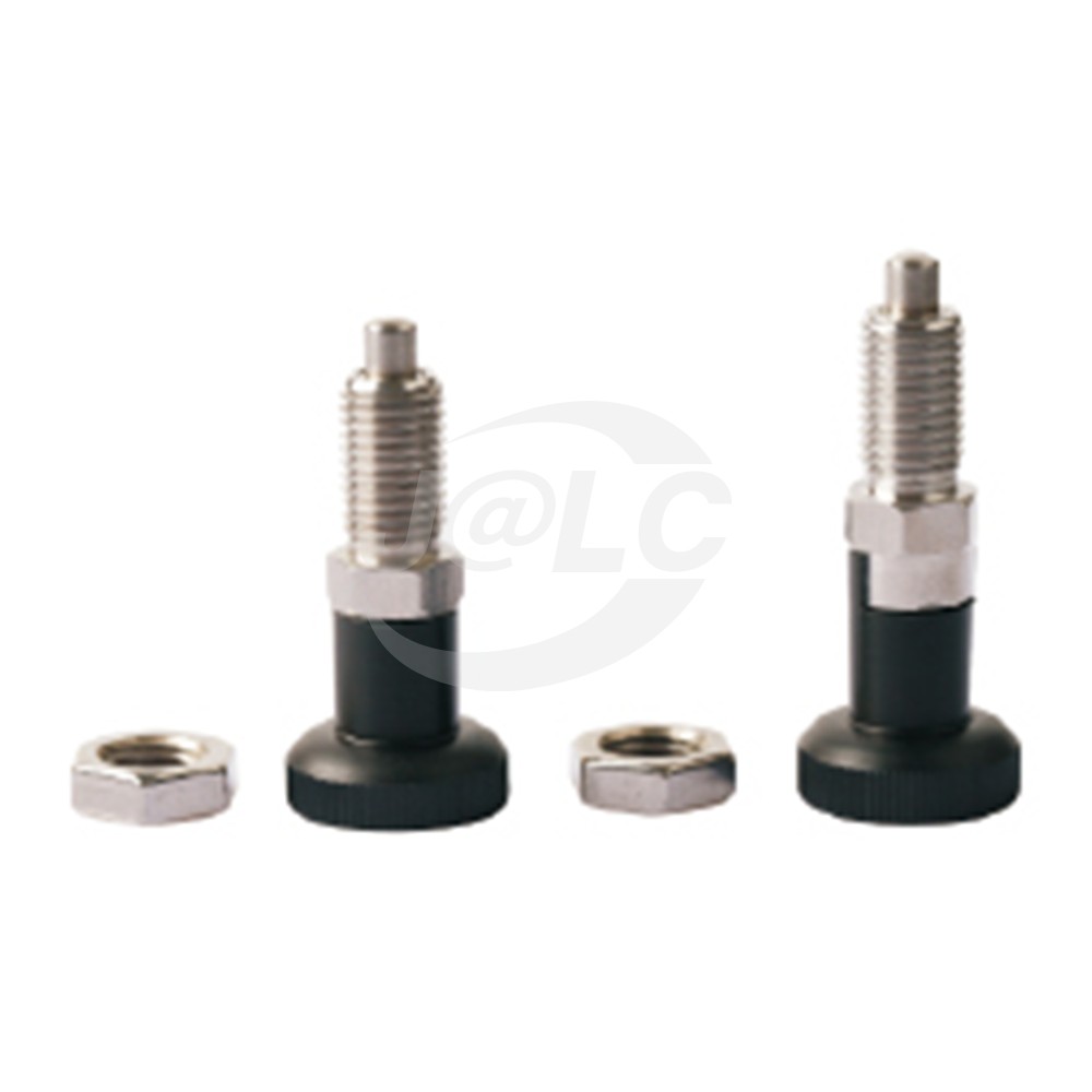
JLCMC FWPM series product image. Check the selected variant's dimensions and supplied accessories separately.
Draw the Engaged and Retracted Positions
A useful installation sketch shows the housing's reference face, maximum and minimum pin projection, the gap to the receiving part, entrance chamfers and available hole depth. Add mounting-plate thickness, washers, lock nuts and any permitted movement of the receiver.
In the retracted state, the pin must clear the swept path of the moving assembly. In the engaged state, it needs the intended straight contact with the receiving hole. These are different checks. A long stroke may solve clearance without providing enough installed projection, while a deeply installed body may improve projection but prevent the knob or housing from moving correctly.
Check blind holes separately. The pin should not bottom in a blind hole before reaching its intended extended condition. Chips or trapped contamination can change the effective depth. A through-hole avoids that particular bottoming limit, but still needs an appropriate entrance and support geometry.
An illustrative engagement stack
For a simplified cylindrical pin and straight receiver, define:
- p: extended projection from the guide's exit face to the pin tip.
- g: gap from that face to the receiving part's entrance face.
- c: combined axial allowance occupied by the pin's lead-in and the receiver's entrance chamfer.
Provided the receiver has enough straight bore length, a conservative planning estimate for straight engagement is $e = p - g - c$. Check the actual geometry in section; a rounded or tapered mating design may require a different analysis.
For a hypothetical installation, p = 8.0 mm, g = 2.5 mm and c = 1.0 mm give 4.5 mm of straight engagement. At the unfavorable tolerances, p = 7.8 mm, g = 3.0 mm and c = 1.2 mm leave 3.6 mm. The nominal result overstates the minimum engagement by 0.9 mm.
These dimensions are illustrative, not FWPM or FWPN specifications. Neither result establishes an acceptable load by itself. The purpose is to expose the dimensional stack before selecting an engagement requirement and checking it against the actual pin and receiving material.
Follow the Load Beyond the Spring
The spring extends the pin along its axis. A force trying to slide the indexed assembly sideways reaches the pin through contact with the receiving feature. The load then passes through the pin guide, body attachment and supporting structure. A spring-force value cannot be substituted for the assembly's transverse load rating.
The gap between the pin guide and receiving feature matters. Under standard mechanical engineering principles (DIN/ISO fixture calculation standards), a pin spanning an open gap must be modeled as a cantilever beam subjected to combined bending moment and transverse shear, rather than pure shear alone. Maximum bending stress scales directly with the unsupported distance across the mounting clearance. Designers must verify both the allowable shear stress across the pin diameter and the contact pressure against the bushing or receiving hole wall.
For your assembly, identify the load direction, expected magnitude and whether it is steady, repeated or an impact. Check the receiving hole's material and wall thickness, the pin's guidance, body mounting and any local plate deflection. Moving the guide closer to the receiver may reduce the unsupported distance, but it must preserve operating clearance throughout adjustment.
A plunger used to identify a position is not automatically a clamp that removes all play. If the process needs firm seating against a stop, define how that seating is produced. If it needs a separate load-bearing lock, specify that function explicitly rather than assuming a larger return spring supplies it.
Compare the Choices by the Required Behavior
| Design question | Reset arrangement | Retracted-rest arrangement | Check for either choice |
|---|---|---|---|
| What happens after the operator lets go? | Commonly attempts spring return | May remain withdrawn until released | Actual product action and clear operator feedback |
| Must the assembly pass several positions? | Operator may need to hold the pin back | Retraction retention can simplify movement | Clearance throughout the adjustment path |
| What proves positioning is complete? | Pin entering the intended receiver | Release from rest followed by entry | Minimum engagement and final part position |
| What determines transverse capacity? | Complete mechanical load path | Complete mechanical load path | Exact product data and receiver/mounting strength |
| What happens during maintenance? | Return action needs checking | Both retention and release need checking | Wear, contamination and mounting security |
This comparison describes common functional arrangements. It does not assign an unverified mechanism to a product carrying only a short catalog label.
Install for Alignment and Service Access
Locate the body so its pin axis aligns with the receiving feature across the permitted adjustment and manufacturing tolerances. Tightening a lock nut can change the final position if the body turns with it. Recheck projection after securing the assembly, using the selected product's fastening instructions.
Reserve room for the full hand or tool movement. A knob may be accessible when extended but collide with a cover when pulled. A retained-retraction mechanism may also need rotation or other motion that is difficult in a crowded bracket. Verify access with the surrounding panels fitted.
Do not use the pin to pull a badly misaligned assembly into position. Establish the intended relationship with the supporting guides and mating features. If the pin is difficult to retract under load, relieve that load through the machine's designed support or adjustment method before releasing it. Pulling harder can conceal an unsuitable load path.
Commission the Complete Positioning Cycle
Test every intended position first without the operating load. Confirm full retraction, unobstructed movement, return or release from rest, and engagement. Then repeat under representative permitted loading, observing the receiver and mounting bracket rather than only the knob.
Include the least favorable gap and alignment conditions that the design allows. Check whether a partially engaged pin gives a misleading indication of completion. Where engagement must be confirmed automatically, use a specifically designed detection arrangement and validate what it actually detects; sensing knob movement is not necessarily sensing pin entry.
Record the chosen part number, receiver geometry, installed projection, permitted adjustment sequence and acceptance observations. After wear or an equipment change, this provides a reference for distinguishing a dirty hole, shifted mounting body and altered operating load.
FAQ about Indexing Plunger Selection
Does releasing the knob guarantee full engagement?
No. The pin can be blocked by misalignment, contamination, a side load or the receiving surface. Verify entry into the intended feature and sufficient engagement.
Is the self-locking version necessarily stronger?
The functional label does not establish greater transverse capacity. Compare the exact pin, body and mounting specifications and determine which state the mechanism retains.
Can I use the spring force as the holding-force rating?
No. Spring force describes axial action. A transverse operating load involves pin bending, contact, guidance and the surrounding structure, which require separate evaluation.
Does a chamfer count as full engagement?
A lead-in helps entry, but it does not provide the same straight contact as a fully seated cylindrical section. Account for both pin and receiver lead-ins in the geometry check.
Can a longer projection fix a mounting gap?
It can increase reach, but may also change unsupported length, clearance and loading. Check the entire installation rather than treating reach alone as adequate support.
Why does the pin work when unloaded but stick during use?
A side load or structural deflection may force the pin against its guide or receiver. Check alignment and the loaded mechanism, and establish a controlled way to remove the load before release.
Conclusion: Indexing Plunger Selection
Choose an indexing plunger by following its full operating cycle and load path. Confirm the required reset or retained-retraction behavior, calculate the installed engagement at unfavorable tolerances, and evaluate the pin together with its receiver and mounting structure. A working knob is only one part of a reliably positioned assembly.
Popular Articles
Keep Learning
Indexing Plunger Selection Guide: Engagement Depth, Reset Mechanism, and Load Paths
Key Takeaways Reset behavior and retention in the retracted position describe operation, not the pin's load capacity. Confirm engagement at the receiving feature rather than relying only on the knob position. Check the minimum available straight engagement after mounting gaps and lead-in geometry are included. Spring force acts along the pin; transverse holding loads also involve the pin, guide, mounting structure and receiving hole. Reduce unnecessary unsupported distance and assess bending where the......
How to Remove a Stripped Hex Socket Screw (Allen Screw)
A stripped Allen screw becomes hard to remove when the hex key no longer grips the socket. The recess might have rounded edges, or rust might hold the thread in place. Before you use force, check what part has damage. The right method depends on whether the problem sits in the socket or deeper in the thread. If you want to remove a stripped hex screw, start with the least harsh method. Clean the socket and test the exact key size first. Move to pliers or an extractor only if simple methods fail. A slo......
How to Remove a Stripped Torx Screw
A stripped Torx screw has a damaged star-shaped recess. Your bit slips, turns inside the head, or fails to grip. Do not start with more force. Extra force often damages the recess further. People removing stripped Torx screws should start with the simplest method first. Clean the recess. Check the bit size. Add steady downward pressure. Move to extraction tools only when basic steps fail. Diagnose the Problem Before Applying More Force A damaged screw head is only one possible problem. Before removing......
What Is a Hex Screw? Hex-Head and Hex-Socket Fasteners Explained
If you ask what is a hex screw, the answer depends on the type of drive. Some people use the term for a screw with an outer six-sided head. Others use it for a screw with a six-sided recess inside the head. Both forms use a hex shape, but the tool sits in a different place. An external hex head works with a wrench or socket. An internal hex socket works with a hex key, also called an Allen key. The right term depends on the fastener standard and the product name used by the maker. Hex Screw Definition......
Understanding Different Types of Hex-Head Screws
Hex socket screws use a six-sided recess inside the head. You turn them with a hex key or hex bit. The basic drive stays similar across the range, but the head shape and screw form change from one type to another. These differences affect head clearance, surface contact, and the role of the screw in the joint. People often group all hex screw types under one name. A socket head cap screw does not serve the same role as a set screw or shoulder screw. You should check the head profile and thread layout ......
Types of Hex Bolts and How to Choose Them
Hex bolts have a six-sided head that fits a wrench or socket. People use them in many joints because the head gives the tool broad contact and easy access. The main differences come from thread length, thread pitch, head form, material, and finish. The types of hex bolts also vary by standard and job. A partially threaded bolt suits one kind of joint, while a fully threaded hexagon-head screw suits another. You should look at the full joint before you choose a fastener. Hex Bolt Types at a Glance The ......