Tap Drill Chart: UNC, UNF, Metric & NPT Drill Sizes
16 min
- What Is a Tap Drill and Why Does Its Size Matter?
- How to Use This Tap Drill Chart
- How Much Thread Engagement Do You Actually Need?
- UNC Tap Drill Chart (Inch, Coarse Threads)
- UNF Tap Drill Chart (Inch, Fine Threads)
- Metric Tap Drill Chart (Coarse Threads)
- NPT Tap Drill Chart (Pipe Threads)
- How Deep Should the Drill Hole Be? Blind Holes vs. Through Holes
- Tap Drill vs. Clearance Drill: Two Different Holes
- Number, Letter, and Fractional Drill Sizes
- Common Tapping Problems Linked to the Wrong Drill Size
- FAQ about Tap Drill Chart
Key Takeaways
- A tap drill creates the hole a tap cuts internal threads into; the drill diameter controls how much full thread the finished hole has.
- For Unified inch threads, drill size = major diameter − 1/TPI (rounded to the nearest standard drill) is a commonly used starting point for approximately 75 percent thread engagement; the actual percentage depends on thread geometry and the specified hole tolerance.
- For metric threads, the quick formula is drill = thread diameter − pitch in millimeters, rounded to the nearest standard drill.
- A slightly larger drill reduces tapping torque and tap breakage risk but leaves a shallower thread; a smaller drill does the opposite.
- Tap drill and clearance drill are two different holes—one is for cutting threads, the other for letting a screw pass through.
- Always verify critical applications against the tap manufacturer's recommendation, since form taps, coatings, and material condition change the optimum hole size.
Tapping a hole looks simple on paper: drill a hole, turn in a tap, done. In practice, the drill diameter is the single variable that decides whether the thread comes out strong, whether the tap survives the cut, and whether the mating screw actually fits. Drill too large and the thread is shallow and strips under load. Drill too small and the tap binds, heats, and snaps off inside the part—often in the middle of an assembly.
This tap drill chart collects the working drill sizes for the thread systems you are most likely to encounter in mechatronic assemblies and machine building: UNC and UNF inch threads, metric coarse threads, and NPT pipe threads. It also explains how to use the numbers, what thread engagement means, and how to adjust when the material in front of you is not textbook mild steel.
What Is a Tap Drill and Why Does Its Size Matter?
A tap drill is the drill used to make the pre-tap hole—the hole that a tap subsequently cuts internal threads into. The tap removes material rather than deforming it (with one exception noted below), so the hole diameter directly sets how much thread height the finished thread has.
The relationship is straightforward:
- Drill too small → more material for the tap to cut → high torque, heat buildup, broken taps, and rough threads.
- Drill too large → less material to cut → easy tapping but shallow, weak threads that can strip when the mating nut or bolt is tightened.
One exception is worth knowing: a form tap (or roll tap) does not cut—it displaces material to form the thread. Form taps need a larger hole than cutting taps of the same thread size, and the exact size depends on the material and the tap design, so it comes from the tap maker's data rather than from the tables here. All tables in this article assume conventional cutting taps.
How to Use This Tap Drill Chart
You can read the charts below directly, but understanding the two formulas behind them makes it easy to sanity-check any number—or handle a thread size that is not listed.
For Unified inch threads, a widely used approximation is:
`` Tap drill (inch) = Major diameter − 1 / TPI (threads per inch) ``
Example: for a 1/4-20 UNC thread, 0.250 − 1/20 = 0.200 inch, which corresponds to a #7 drill (0.201 inch). The formula is a commonly used starting point for approximately 75 percent thread engagement, but the actual percentage depends on thread geometry and the specified hole tolerance.
For metric threads, the shortcut is:
`` Tap drill (mm) = Thread diameter (mm) − Pitch (mm) ``
Example: for an M6 × 1.0 thread, 6.0 − 1.0 = 5.0mm drill.
A drill and tap chart like this is a sizing aid, not a guarantee: the exact engagement it produces varies with thread geometry, and drill availability often forces a nearby substitute—which is why the tables also give the nearest metric equivalents for inch sizes.
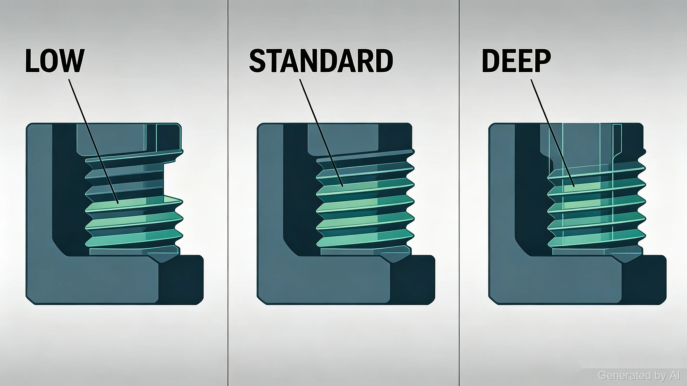
How Much Thread Engagement Do You Actually Need?
Thread engagement is the share of the theoretical full thread height that actually gets cut in the hole. The long-standing shop rule of thumb targets about 75 percent engagement for general work in steel. The logic is a trade-off:
- Increasing thread engagement beyond roughly 60–75 percent generally provides diminishing returns in thread strength while significantly increasing tapping torque: the first few threads carry the bulk of the load.
- Dropping to around 60–65 percent engagement makes tapping noticeably easier and can be acceptable in softer materials or non-critical joints, but it reduces stripping strength and gives less margin against vibration loosening.
The 75 percent target is a convention, not a law. For softer materials such as aluminum, thread strength is often improved by providing sufficient thread engagement length rather than simply increasing the percentage of thread depth. Hard, abrasive, or high-strength materials may require a larger tap drill to reduce tapping torque. For joints that carry real loads, the most reliable answer is to follow the tap manufacturer's recommended hole size for the specific material and tap rather than a single universal number.
UNC Tap Drill Chart (Inch, Coarse Threads)
UNC (Unified National Coarse) is the most common inch thread family in general machinery and assembly work. Sizes below follow the customary ~75 percent engagement recommendation for cutting taps.
| Thread | Threads per Inch | Tap Drill | Decimal (in) | Approx. mm |
|---|---|---|---|---|
| #1-64 | 64 | #53 | 0.0595 | 1.5 |
| #2-56 | 56 | #51 | 0.067 | 1.7 |
| #3-48 | 48 | #47 | 0.0785 | 2.0 |
| #4-40 | 40 | #43 | 0.089 | 2.3 |
| #5-40 | 40 | #38 | 0.1015 | 2.6 |
| #6-32 | 32 | #36 | 0.1065 | 2.7 |
| #8-32 | 32 | #29 | 0.136 | 3.5 |
| #10-24 | 24 | #25 | 0.1495 | 3.8 |
| #12-24 | 24 | #16 | 0.177 | 4.5 |
| 1/4-20 | 20 | #7 | 0.201 | 5.1 |
| 5/16-18 | 18 | F | 0.257 | 6.5 |
| 3/8-16 | 16 | 5/16 | 0.3125 | 7.9 |
| 7/16-14 | 14 | U | 0.368 | 9.3 |
| 1/2-13 | 13 | 27/64 | 0.4219 | 10.7 |
| 5/8-11 | 11 | 17/32 | 0.5313 | 13.5 |
| 3/4-10 | 10 | 21/32 | 0.6563 | 16.7 |
| 7/8-9 | 9 | 49/64 | 0.7656 | 19.4 |
| 1-8 | 8 | 7/8 | 0.875 | 22.2 |
This table is a general reference for cutting taps in common materials. It does not replace the tap manufacturer's recommendation, which takes priority for form taps, coated taps, exotic alloys, and safety-critical joints.
UNF Tap Drill Chart (Inch, Fine Threads)
UNF (Unified National Fine) threads have more threads per inch at the same nominal size. The finer pitch means a slightly larger drill relative to the major diameter compared with UNC.
| Thread | Threads per Inch | Tap Drill | Decimal (in) | Approx. mm |
|---|---|---|---|---|
| #0-80 | 80 | 3/64 | 0.0469 | 1.2 |
| #1-72 | 72 | #51 | 0.067 | 1.7 |
| #2-64 | 64 | #50 | 0.070 | 1.8 |
| #3-56 | 56 | #45 | 0.082 | 2.1 |
| #4-48 | 48 | #42 | 0.0935 | 2.4 |
| #5-44 | 44 | #37 | 0.104 | 2.6 |
| #6-40 | 40 | #33 | 0.113 | 2.9 |
| #8-36 | 36 | #29 | 0.136 | 3.5 |
| #10-32 | 32 | #21 | 0.159 | 4.0 |
| #12-28 | 28 | #14 | 0.182 | 4.6 |
| 1/4-28 | 28 | #3 | 0.213 | 5.4 |
| 5/16-24 | 24 | I | 0.272 | 6.9 |
| 3/8-24 | 24 | Q | 0.332 | 8.4 |
| 7/16-20 | 20 | W | 0.386 | 9.8 |
| 1/2-20 | 20 | 29/64 | 0.4531 | 11.5 |
| 5/8-18 | 18 | 37/64 | 0.5781 | 14.7 |
| 3/4-16 | 16 | 11/16 | 0.6875 | 17.5 |
The same disclaimer applies here: these are conventional cutting-tap starting points, not a substitute for manufacturer data on a specific job.
Metric Tap Drill Chart (Coarse Threads)
Metric coarse threads follow the drill = diameter − pitch relationship closely enough that this chart is easy to reconstruct from memory when a size is not listed. The values below are rounded to standard drill sizes.
| Thread | Pitch (mm) | Tap Drill (mm) |
|---|---|---|
| M1.6 | 0.35 | 1.25 |
| M2 | 0.4 | 1.6 |
| M2.5 | 0.45 | 2.05 |
| M3 | 0.5 | 2.5 |
| M4 | 0.7 | 3.3 |
| M5 | 0.8 | 4.2 |
| M6 | 1.0 | 5.0 |
| M8 | 1.25 | 6.8 |
| M10 | 1.5 | 8.5 |
| M12 | 1.75 | 10.2 |
| M14 | 2.0 | 12.0 |
| M16 | 2.0 | 14.0 |
| M20 | 2.5 | 17.5 |
| M24 | 3.0 | 21.0 |
Metric fine threads (for example M6 × 0.75) use the same formula with the fine pitch, though the approximation loosens as pitch shrinks. The chart above covers coarse threads only; fine-pitch applications should be confirmed against the drawing or the tap maker's data. For a deeper look at metric screw sizes and their applications, see our M3–M6 screws guide.
NPT Tap Drill Chart (Pipe Threads)
NPT (National Pipe Taper) threads seal through thread interference rather than a gasket, so the tapped hole geometry matters even more than usual.
Important: NPT Does Not Use the Standard Formula
NPT tap drill sizes are not calculated using the standard diameter-minus-pitch formula. NPT is a tapered pipe thread, so drill size, tapping depth, and thread engagement must follow the applicable standard and the tap manufacturer's specifications.
| NPT Size | Threads per Inch | Tap Drill | Decimal (in) |
|---|---|---|---|
| 1/16 | 27 | D | 0.246 |
| 1/8 | 27 | R or 11/32 | 0.339–0.344 |
| 1/4 | 18 | 7/16 | 0.438 |
| 3/8 | 18 | 37/64 | 0.578 |
| 1/2 | 14 | 45/64 | 0.703 |
| 3/4 | 14 | 29/32 | 0.906 |
| 1 | 11-1/2 | 1-5/32 | 1.156 |
Because NPT threads are tapered and designed to provide a pressure-tight joint, tapping depth, thread condition, and sealant practice all affect leak-tightness. Treat this chart as a starting point and confirm against the fitting standard your application references.
How Deep Should the Drill Hole Be? Blind Holes vs. Through Holes
The chart answers "how wide"—but in blind holes (holes that do not exit the part), depth matters just as much. A standard hand tap has a tapered lead of several threads that cannot cut full-profile threads, and chips need somewhere to go.
- Through holes: drill all the way through the part; chips exit the far side and the thread can run the full material thickness.
- Blind holes: the drilled depth is commonly specified deeper than the usable thread depth—typically enough for the tap's chamfered lead (a plug tap adds three to five threads of taper) plus additional chip clearance at the bottom.
Example: for a usable thread depth of 10mm on an M6 × 1.0 thread, a drilled depth in the 13–14mm range is a typical starting point. This is an illustrative example, not a universal depth rule: the exact value depends on the tap chamfer, tap style, required full-thread depth, chip space, and hole bottom geometry. A bottoming tap can bring usable threads closer to the bottom of the hole than a standard taper or plug tap, which is one of the reasons tap selection matters in shallow blind holes.
Tap Drill vs. Clearance Drill: Two Different Holes
Tap drill and clearance drill are two different holes for two different parts—one cuts threads, the other lets the screw pass. Mixing them up is one of the most common fastening errors:
- Tap drill: slightly smaller than the bolt's major diameter, so the tap can cut threads into the hole. Used on the receiving part.
- Clearance drill: slightly larger than the bolt's major diameter, so the bolt slips through freely. Used on the part being clamped.
For example, an M6 screw passes through a 6.6mm clearance hole in a mounting plate but threads into a 5.0mm tap-drilled hole in the base part. If a clearance hole is drilled too small the screw binds; if a tap hole is drilled at clearance size the mating thread has nothing to bite. When the receiving hole material is too thin for a useful thread—or needs repeated assembly—threaded inserts restore a durable internal thread; our threaded inserts guide covers that topic in detail.
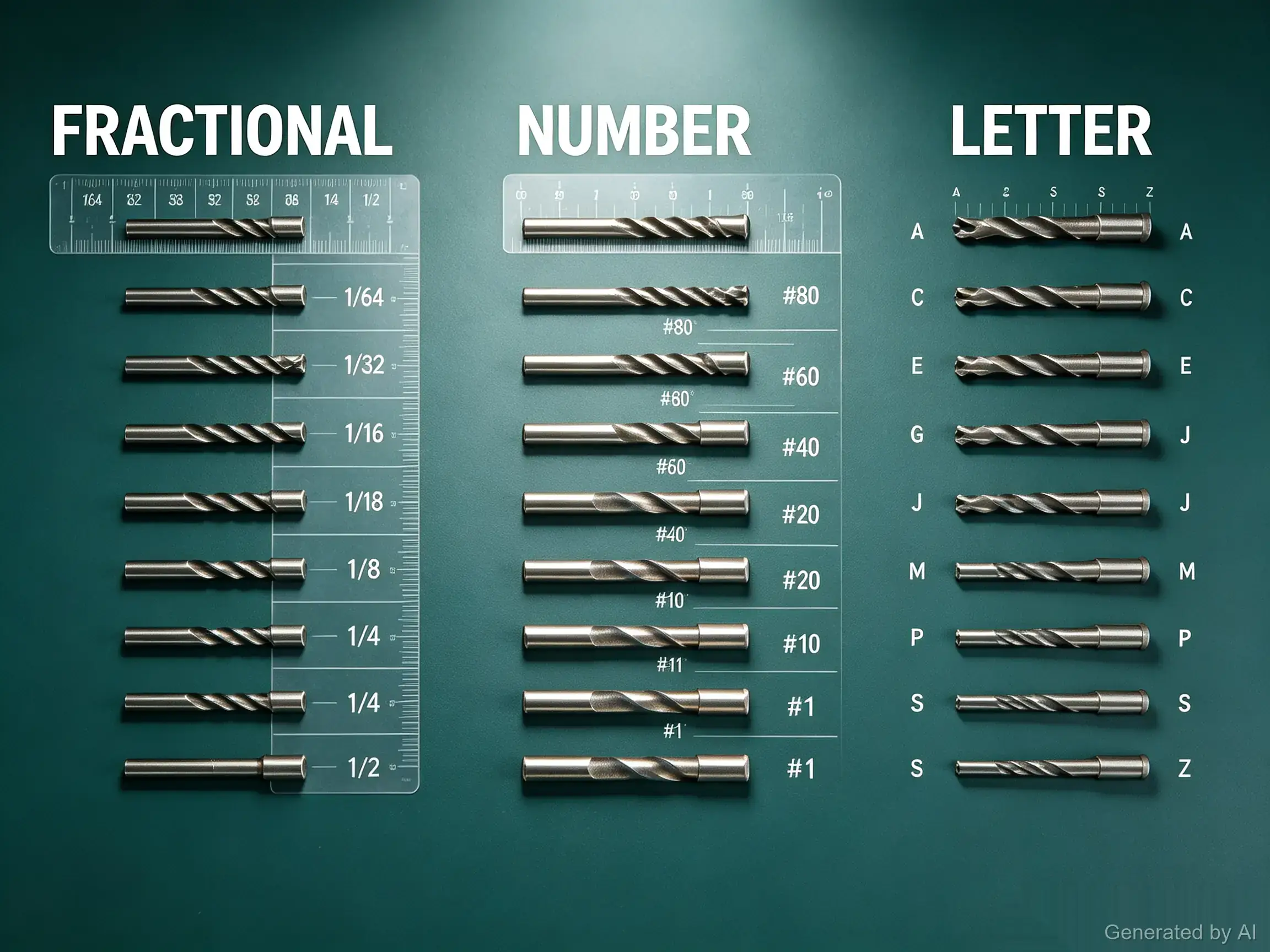
Number, Letter, and Fractional Drill Sizes
The inch drill charts above mix three sizing systems, which confuses many first-time buyers:
- Fractional sizes (1/64 inch steps from 1/16 upward): the oldest system, covering the large end of the range.
- Number sizes (#80 through #1, roughly 0.0135–0.228 inch): fill the fine gaps between 1/16 and 1/4 inch. This is why 1/4-20 takes a #7 drill—no fractional drill matches it exactly (13/64 inch comes close at 0.203).
- Letter sizes (A through Z, 0.234–0.413 inch): continue the series above #1 up to 13/32 inch.
A workshop drilling set that includes all three systems removes most "nearest substitute" compromises when tapping inch threads.
Common Tapping Problems Linked to the Wrong Drill Size
Tapping complaints trace back to the hole more often than to the tap:
- Tap breakage: usually an undersized drill, a worn tap, or chip packing in a blind hole. The tap is often the first suspect, though the hole is the more frequent root cause.
- Oversized or sloppy threads: typically an oversized drill or a wobbling setup; the finished joint rattles or strips at low torque.
- Excessive tapping torque: a marginal drill size combined with a hard material, dull tap, or insufficient lubrication. Increasing the tap-drill diameter slightly can reduce tapping torque, but the resulting thread engagement should be checked against the required thread strength and the tap manufacturer's recommendation.
- Rough or torn threads: soft materials and small drills tend to tear rather than cut cleanly; sharp taps and correct speed matter as much as the chart value here.
When a tapped hole in thin sheet or soft material does fail, recovery options range from re-tapping one size up to installing an insert—the repair paths are the same ones used for stripped screws, which our threaded inserts for metal guide walks through.
FAQ about Tap Drill Chart
Q: What size drill bit do I need for a 1/4-20 tap?
A #7 drill (0.201 inch, about 5.1mm) is the conventional choice for 1/4-20 UNC, giving roughly 75 percent thread engagement. For easier tapping in tough material, a 5.2mm drill is a common substitute.
Q: What is the drill size for a 3/8-16 tap?
A 5/16 inch (7.9mm) drill is the standard recommendation for a 3/8-16 UNC thread. Fine-thread 3/8-24 instead uses a Q drill (0.332 inch, about 8.4mm).
Q: What is the tap drill size for M6?
A 5.0mm drill is the standard choice for M6 × 1.0, the common coarse pitch (6.0 − 1.0 = 5.0mm). Fine-pitch variants such as M6 × 0.75 need a larger drill—about 5.25mm—confirmed against the drawing or the tap maker's data.
Q: What is the tap drill size for M8?
A 6.8mm drill is the standard choice for M8 × 1.25 coarse thread (8.0 − 1.25 = 6.8mm). The fine-pitch M8 × 1.0 uses a 7.0mm drill instead.
Q: Should I use a larger tap drill for aluminum?
Not automatically. A larger drill reduces tapping torque, which helps where tapping tends to bind, but it also leaves a shallower thread. In softer materials such as aluminum, thread strength is often improved by providing sufficient thread engagement length rather than increasing the percentage of thread depth, so check the required strength and the tap manufacturer's recommendation before changing the drill size.
Q: How do I calculate tap drill size without a chart?
For inch threads, subtract 1 divided by the threads per inch from the major diameter. For metric threads, subtract the pitch from the thread diameter. Both give a starting point of approximately 75 percent thread engagement for cutting taps; the actual percentage depends on thread geometry and the specified hole tolerance.
Q: What happens if the tap drill is too small?
Tapping torque rises sharply, heat builds up, and the tap can jam or break inside the hole—often ruining the part. A broken tap is one of the most expensive small mistakes in assembly work.
Q: Is the same drill size used for form taps?
No. Form taps require a larger pre-hole than cutting taps because they form rather than cut the thread. The required hole size depends on the material and tap design, so always use the tap maker's form-tap hole size rather than a cutting-tap chart.
Q: Why does the chart show both number drills and metric sizes?
Drill availability differs by region and workshop. Showing the nearest metric equivalent for inch sizes lets you substitute a metric drill when the exact number or letter drill is not on hand, with only a small change in thread engagement.
Conclusion: Tap Drill Chart
A tap drill chart is a small tool with outsized consequences: the drill you pick before tapping determines thread strength, tapping torque, and whether the tap comes back out of the hole intact. The formulas—major diameter minus 1/TPI for inch threads, diameter minus pitch for metric—let you reconstruct most values on the spot, while the charts above give the standard starting points for UNC, UNF, metric coarse, and NPT threads.
Treat the values as engineering starting points rather than certainties: material, tap type, and application loads all shift the optimum hole size, and the manufacturer's recommendation always takes priority. Once the thread is cut, the rest of the joint is hardware selection—matched screws, nuts, and inserts for thin or repairable holes. Need the hardware for your next build? Explore JLCMC's selection of screws, nuts, threaded inserts, and other mechatronic components.
Keep Learning
Drill Bit Size Chart: Number, Letter, Fractional & Metric
Key Takeaways A drill bit size chart has to cover four systems — fractional (inches), number (#1–#80), letter (A–Z), and metric (mm) — because the same physical diameter can carry three different callouts. Number sizes provide intermediate diameters between standard fractional-inch drill sizes, allowing finer selection where 1/64-inch increments are too coarse — which is why a 1/4-20 tap takes a #7 drill (0.201 inch). Convert decimal inches to millimeters by multiplying by 25.4; the charts below give ......
2-Bolt vs. 4-Bolt Flange Bearing Units: Selection Differences That Matter
Key Takeaways Housing geometry and space: A two-bolt flange bearing unit normally uses an oval or diamond-shaped housing, making it ideal when the mounting face is narrow or access is limited. Bolt count vs. capacity: A four-bolt flange bearing unit normally uses a square housing suited for wider interfaces, but bolt count alone does not establish the unit's load capacity. Machine interface priority: Choose the housing pattern based on the machine interface first. Then verify shaft size, published loa......
NPT Thread Guide: Charts, Tap Drill Sizes, and Fitting Identification
Key Takeaways NPT (National Pipe Taper) is a U.S. standard tapered pipe thread defined by ASME B1.20.1: a 60° thread angle and a 1:16 taper on diameter, sealing through thread interference plus sealant. NPT tap drill sizes do not follow the diameter-minus-pitch formula used for straight machine threads — ASME B1.20.1 Appendix B provides guidance, and the tap manufacturer's data decides. The everyday sizes: 1/8 NPT (27 TPI, 0.405 inch major diameter), 1/4 NPT (18 TPI, 0.540 inch), 1/2 NPT (14 TPI, 0.84......
Tap Drill Chart: UNC, UNF, Metric & NPT Drill Sizes
Key Takeaways A tap drill creates the hole a tap cuts internal threads into; the drill diameter controls how much full thread the finished hole has. For Unified inch threads, drill size = major diameter − 1/TPI (rounded to the nearest standard drill) is a commonly used starting point for approximately 75 percent thread engagement; the actual percentage depends on thread geometry and the specified hole tolerance. For metric threads, the quick formula is drill = thread diameter − pitch in millimeters, r......
Comparing Brushless Motors and Stepper Motors: Principles, Structures & Applications
We have many machines around us that have electric motors to operate, including simple tools and complex robots. Brushless DC (BLDC) motors and stepper motors are two popular options for high precision and performance. They are both electrically commutated motors and have no physical brushes, but operate in different ways and are appropriate for different applications. Key Takeaways The advantages of BLDC motors are high-speed, smooth, continuous operation, and high efficiency. Stepper motors can be u......
DC Motor vs. Stepper Motor: What Are They and How Do They Differ?
To clearly distinguish between DC motors and stepper motors, this article uses brushed DC motors as the primary reference for comparison. A brushed DC motor is typically well suited for continuous rotation, high-speed operation, and variable-speed control, while a stepper motor is commonly used for low-speed positioning, indexing, and holding torque at standstill. When combined with an encoder and an appropriate controller, a brushed DC motor can also be used for closed-loop positioning. The right cho......