Threaded Standoff Guide: Types, Sizes, Materials and Applications
15 min
- 1. What Is a Threaded Standoff?
- 2. Threaded Standoff vs Spacer vs Stud
- 3. Main Types of Threaded Standoff
- 4. Hex, Round and Special Mounting Styles
- 5. How to Read Threaded Standoff Sizes
- 6. Thread Engagement, Screw Length and Load
- 7. Common Threaded Standoff Materials
- 8. Mechanical, Electrical and Environmental Considerations
- 9. How to Choose the Right Threaded Standoff
- 10. Installation and Maintenance
- 11. Common Selection and Installation Mistakes
- FAQ about Threaded Standoff
Key Takeaways
Thread configuration first: Choose female-female, male-female or male-male based on how both sides of the assembly attach — thread config is the most practical way to classify a threaded standoff.
Body length is the critical dimension: Standoff length refers to the distance between supporting faces, not total physical length. Reading the wrong length causes incorrect mounting height or screw bottoming.
Material affects more than strength: Brass, stainless steel, carbon steel, aluminum and nylon each trade off strength, weight, corrosion resistance, conductivity and temperature capability — match the material to the full operating environment.
Validate the complete stack-up: A technically correct standoff can still create an incorrect assembly. Prototype and inspect the full joint when mounting height, alignment, grounding or vibration performance matters.
A threaded standoff is a fixed-length fastener that separates, positions and secures two components. Also called a threaded standoff spacer, it combines a rigid spacing body with internal threads, external threads or both.
Threaded standoffs are commonly found beneath printed circuit boards, between enclosure panels, behind sensors and inside automation equipment. Although the part looks simple, choosing one involves more than matching an M3 screw to an M3 hole. Body length, thread engagement, material, load direction, electrical behavior and installation access all influence the final assembly.
This guide explains threaded standoff types, dimensions, materials, selection methods and applications in electronics, machinery and mechatronic systems.
1. What Is a Threaded Standoff?
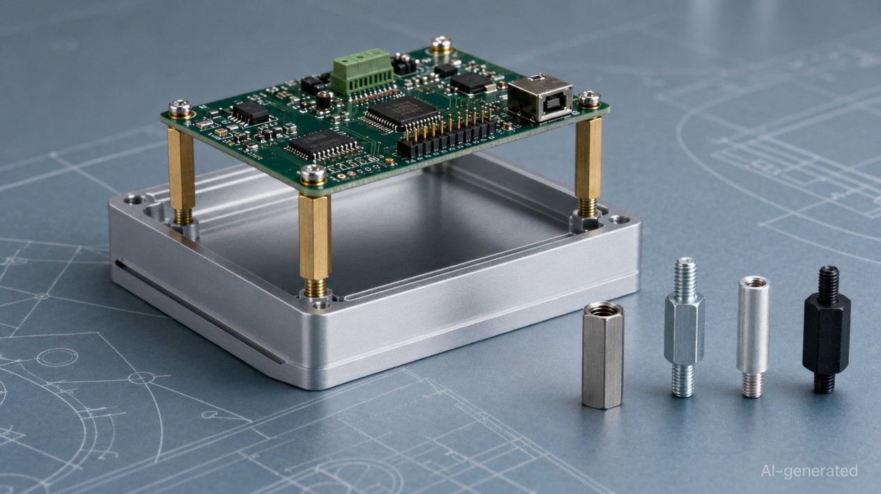
A threaded standoff is a fixed-length separator with internal and/or external machine threads. It maintains a controlled gap between components while providing threaded attachment points.
In a typical PCB assembly, a male-female standoff screws into a tapped enclosure base. The circuit board rests on the upper face, and a machine screw passes through the board into the female thread. The body establishes the mounting height while the threaded connections secure the assembly.
A threaded standoff may be used to:
- support a PCB, panel or bracket;
- create clearance for components and cables;
- align stacked parts;
- improve airflow and service access;
- carry compression, tension, shear or bending loads;
- provide an electrical path;
- maintain electrical isolation.
The spacing function is just as important as the fastening function. If the body length is wrong, the screws may fit perfectly while the enclosure still refuses to close — a small component with an impressive talent for causing large problems.
2. Threaded Standoff vs Spacer vs Stud
The terms standoff, spacer and stud are sometimes used interchangeably, but they do not always describe the same component.
A product described as a threaded spacer usually performs the same function as a threaded standoff. However, an unthreaded spacer depends on a separate screw or bolt passing through it.
A double-ended stud can resemble a male-male standoff, but it may not provide precision spacing. If mounting height matters, check the body length, supporting faces and dimensional tolerance instead of relying only on the product name.
| Component | Typical construction | Main function |
|---|---|---|
| Threaded standoff | Fixed-length body with internal and/or external threads | Spaces, positions and fastens components |
| Spacer | Usually an unthreaded sleeve with a through-hole | Maintains distance while a separate fastener clamps the assembly |
| Threaded stud | Shank with external threads on one or both ends | Joins threaded components or provides a projecting thread |
3. Main Types of Threaded Standoff
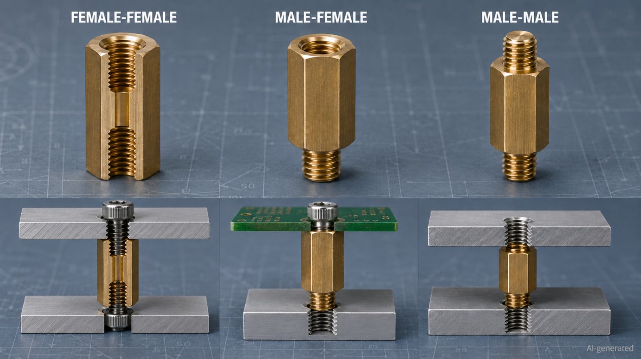
Thread configuration is the most practical way to classify a threaded standoff.
Female-female threaded standoff
A female-female standoff accepts a screw from each end. Its internal thread may pass through the entire body or consist of two separate blind holes.
For blind versions, usable thread depth must be checked carefully. If the screw reaches the bottom of the hole before clamping the component, the joint may feel tight without actually being secure.
Male-female threaded standoff
A male-female standoff screws directly into a tapped base and accepts a machine screw at the opposite end. It is widely used for PCB mounting, enclosure panels, sensors and control hardware.
Some versions use the same thread size at both ends. Adapter standoffs may combine different sizes, such as an M4 male thread with an M3 female thread.
Male-male threaded standoff
A male-male standoff connects two tapped components while maintaining a defined gap. It is suitable for parallel plates, fixtures, sensor brackets and layered mechanical assemblies.
The male threads may have equal or different lengths. Both lengths must be checked against the available tapped-hole depth.
| Type | Construction | Best suited to |
|---|---|---|
| Female-female | Internal thread at both ends | Assemblies using removable screws on both sides |
| Male-female | External thread at one end and internal thread at the other | Tapped bases, PCB mounting and stackable assemblies |
| Male-male | External threads at both ends | Joining two tapped components at a controlled distance |
4. Hex, Round and Special Mounting Styles
Threaded standoffs are available with different body shapes and installation methods.
A hex standoff has wrench flats that make it easier to hold and tighten. Hex bodies are usually preferred in machinery, control enclosures and serviceable assemblies where controlled installation is important.
A round standoff uses less radial space and provides a cleaner appearance. If tightening torque must be controlled, the round body should include a slot, flats, knurling or another suitable drive feature.
Other mounting styles include:
- self-clinching standoffs;
- press-fit standoffs;
- swage standoffs;
- weld standoffs;
- surface-mount PCB standoffs;
- snap-in or push-fit plastic standoffs.
These mounting styles require different hole preparation and installation equipment. A self-clinching standoff, for example, should not be treated as a direct replacement for a screw-mounted standoff simply because the thread size and body length are similar.
5. How to Read Threaded Standoff Sizes
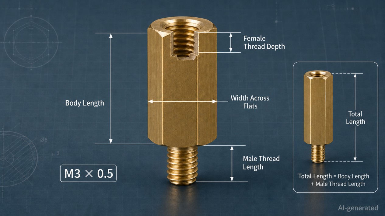
A threaded standoff drawing usually contains several dimensions. Reading the wrong length can place a PCB at the wrong height or cause a screw to bottom out.
For metric threads, M3 × 0.5 indicates a nominal major diameter of 3 mm and a pitch of 0.5 mm. A catalog may list the part simply as M3 when it uses the standard coarse pitch, but the pitch should still be confirmed.
Imperial threaded standoffs may use sizes such as #4-40, #6-32 or #8-32. Metric and inch threads that appear similar are not interchangeable.
Body length normally means the distance between the two supporting faces. It usually excludes a projecting male thread.
For example, a male-female standoff may have:
- M3 male thread;
- M3 female thread;
- 10 mm body length;
- 6 mm male thread length.
The controlled spacing is 10 mm, while the approximate total physical length is 16 mm. Always identify the supporting faces on the drawing before selecting the standoff height.
| Dimension | Meaning | Why it matters |
|---|---|---|
| Thread size | Nominal thread diameter and pitch or threads per inch | Must match the mating screw or tapped hole |
| Body length | Distance between the two supporting faces | Determines the nominal spacing |
| Male thread length | Length of the projecting external thread | Controls available engagement and bottoming risk |
| Female thread depth | Usable depth of the internal thread | Limits screw penetration |
| Width across flats | Wrench size for a hex body | Determines tooling and radial clearance |
| Outside diameter | Diameter of a round body | Affects packaging space and supporting area |
6. Thread Engagement, Screw Length and Load
Correct thread engagement is essential to joint strength.
The male thread must engage far enough to support the required load without bottoming in a blind tapped hole. The mating screw must also clamp the mounted component before reaching the end of the female thread.
For a through-threaded female-female standoff, screws entering from opposite ends may interfere if they are too long. The following relationship should therefore be checked:
Screw penetration + opposite screw penetration ≤ available internal length
The appropriate engagement depends on:
- thread diameter and pitch;
- standoff material;
- mating material;
- load direction;
- manufacturing tolerance;
- vibration and shock;
- expected assembly cycles.
A universal rule such as "one thread diameter is always enough" should not replace supplier data or engineering validation.
Load direction also matters. A standoff may experience:
- compression from clamping;
- tension or pull-out;
- lateral shear;
- bending from offset loads;
- vibration and repeated shock.
Tall, slender standoffs are more sensitive to bending than shorter standoffs with the same thread size. Increasing the number of standoffs can improve support, but only when their locations and body-length tolerances prevent the mounted part from rocking or warping.
Quick Tip
Never assume "one thread diameter" of engagement is sufficient. Always verify with supplier data or an engineering joint calculation, especially for critical load-bearing applications.
7. Common Threaded Standoff Materials
Material affects strength, weight, corrosion resistance, conductivity, temperature capability and thread durability.
Brass is widely used for electronic hardware because it machines cleanly and provides reliable internal and external threads. Nickel plating may improve appearance and corrosion resistance, although coatings can affect electrical contact.
Stainless steel is suitable for demanding mechanical or corrosive environments. Anti-galling measures may be necessary when stainless steel threads are repeatedly assembled.
Plated carbon steel offers a practical balance between strength and cost, but the coating must suit the operating environment.
Aluminum reduces weight, although softer threads may wear during repeated servicing.
Nylon and other engineering plastics provide electrical isolation. However, continuous loading and elevated temperatures can produce creep, causing the mounting height or clamp condition to change over time.
The exact alloy, steel grade or plastic formulation is more important than the broad material name.
| Material | Main advantages | Points to check | Typical applications |
|---|---|---|---|
| Brass | Good machinability, accurate threads and electrical conductivity | Weight, strength and plating condition | PCB mounting, instruments and electronics |
| Stainless steel | High strength and corrosion resistance | Cost, weight and possible thread galling | Industrial, outdoor and corrosive environments |
| Carbon steel | Good strength and cost efficiency | Protective coating and corrosion exposure | Machinery, fixtures and general equipment |
| Aluminum | Low weight and good machinability | Thread wear and galvanic compatibility | Lightweight instruments and mobile systems |
| Nylon or engineering plastic | Electrical insulation, low weight and corrosion resistance | Creep, temperature, moisture and lower stiffness | Light-load PCB and insulated assemblies |
8. Mechanical, Electrical and Environmental Considerations
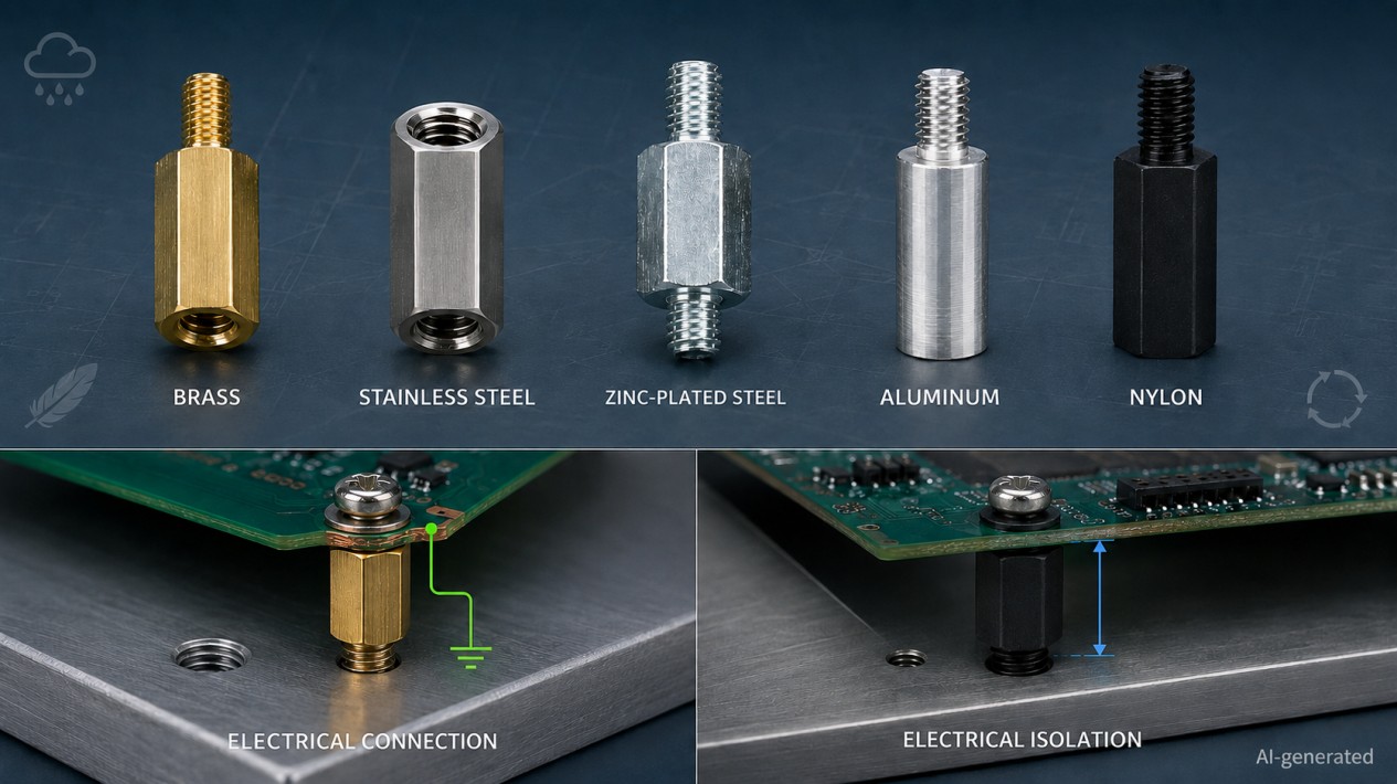
A threaded standoff can affect more than mechanical spacing.
For structural applications, consider:
- compression and tensile loads;
- shear and bending;
- mounting-hole strength;
- body-length tolerance;
- vibration and shock;
- fatigue from repeated movement.
For electrical applications, determine whether the standoff should provide grounding or insulation.
A metal standoff does not automatically create a reliable ground path. Paint, anodizing, plating, washers and surface contamination may increase electrical resistance. If grounding is required, continuity should be tested in the completed assembly.
An insulating standoff must also provide sufficient creepage and clearance for the complete system. Body length alone does not guarantee electrical safety because nearby screws, washers and conductive surfaces may reduce the actual distance.
Environmental conditions may include:
- humidity and condensation;
- salt or corrosive chemicals;
- outdoor exposure;
- elevated or cycling temperatures;
- cleaning fluids;
- vacuum or clean-process requirements.
When dissimilar metals are exposed to moisture, galvanic compatibility should be evaluated. A technically strong standoff is not especially useful if it quietly encourages the surrounding panel to corrode.
9. How to Choose the Right Threaded Standoff
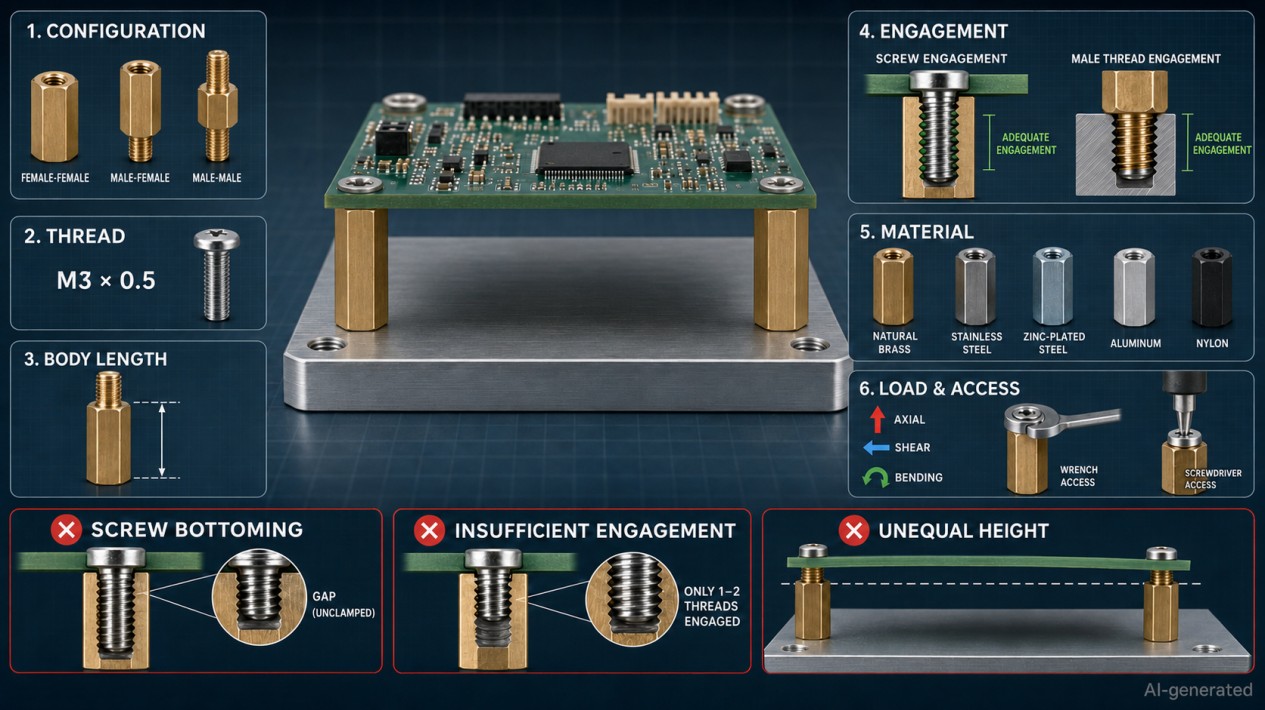
A reliable selection process begins with the assembly requirements rather than the catalog filter.
-
Define the function
Determine whether the standoff must provide controlled clearance, structural support, alignment, grounding, isolation or repeated service access.
-
Select the thread configuration
Tapped base with a clearance hole above: usually male-female. Clearance holes on both sides: usually female-female. Tapped components on both sides: usually male-male.
-
Confirm the thread
Verify the thread system, nominal diameter and pitch. Confirm that both mating components use the same specification.
-
Calculate the body length
Include: component height, connector clearance, cable bend radius, airflow, enclosure position, electrical clearance, board deflection, and manufacturing tolerances. Do not choose the standoff height only from the tallest visible component — connector latches and cable bends have a habit of joining the design review late.
-
Check thread engagement and load
Confirm male thread length, female thread depth, mating screw length and the expected mechanical loads.
-
Select material and finish
Balance strength, weight, temperature, corrosion, electrical behavior and cost.
-
Confirm installation access
Make sure the required wrench, socket or screwdriver can reach the joint during both assembly and maintenance.
-
Validate the complete stack-up
A technically correct individual component can still create an incorrect assembly. Prototype and inspect the complete joint whenever mounting height, alignment, grounding or vibration performance is important.
10. Installation and Maintenance
The exact installation process depends on the standoff style. A conventional screw-mounted threaded standoff can usually be installed as follows:
-
Confirm the thread size, body length, material and drawing.
-
Inspect the threads for damage, burrs and contamination.
-
Start the connection by hand to prevent cross-threading.
-
Tighten the standoff through its hex flats or specified drive feature.
-
Position the mounted component.
-
Install the mating screw.
-
Inspect seating, alignment and the final gap.
Do not grip an external thread with pliers. This can damage the thread profile and create installation problems that appear later.
There is no universal tightening torque for every threaded standoff. Suitable torque depends on:
- thread size;
- standoff material;
- mating material;
- thread engagement;
- surface finish;
- joint function;
- mounted-component strength.
Use supplier data or a value established through joint testing.
For vibration-prone equipment, consider a compatible threadlocker, locking washer or standoff with a locking feature. The retention method must suit the material, temperature and service requirements.
During maintenance, inspect for:
- loosened connections;
- corrosion;
- cracked plastic standoffs;
- damaged threads;
- permanent deformation;
- changing PCB or panel alignment.
11. Common Selection and Installation Mistakes
Many threaded standoff problems are caused by small specification errors rather than part failure.
| Mistake | Likely result | Better approach |
|---|---|---|
| Treating total length as body length | Incorrect mounting height | Identify the supporting faces on the drawing |
| Mixing metric and inch threads | Cross-threading or weak engagement | Confirm diameter and pitch on both parts |
| Ignoring female thread depth | Screw bottoms before clamping | Calculate penetration through the full stack |
| Using an excessively long screw | Internal interference or component damage | Select screw length from stack thickness and usable depth |
| Applying excessive torque | Damaged thread, PCB or panel | Use validated torque and suitable tooling |
| Assuming every metal standoff provides grounding | Unreliable electrical path | Test continuity in the complete assembly |
| Selecting plastic only by material name | Creep or dimensional change | Verify resin, temperature and continuous load |
| Ignoring galvanic compatibility | Corrosion between dissimilar metals | Evaluate materials, finishes and moisture exposure |
| Using unequal standoff heights | Rocking or warped components | Control body-length tolerance and mounting flatness |
| Ignoring tool clearance | Difficult assembly or maintenance | Review the full installation sequence |
When diagnosing an assembly problem, check the drawing and stack-up before replacing the standoff with a stronger material. A stronger part cannot correct the wrong mounting height or an overlong screw.
FAQ about Threaded Standoff
Q: Is a threaded standoff the same as a threaded spacer?
The terms often describe the same product. In stricter usage, a standoff includes threads, while a spacer is usually an unthreaded sleeve captured by a separate fastener.
Q: What does M3 mean on a standoff?
M3 identifies a metric thread with a nominal major diameter of 3 mm. The thread pitch must also match the mating screw or tapped hole.
Q: How is threaded standoff length measured?
Standoff length normally refers to the body length between the supporting faces. A projecting male thread is generally excluded, but the product drawing should always be checked.
Q: Which is better: a hex standoff or a round standoff?
A hex standoff is easier to hold and tighten with a wrench. A round standoff uses less radial space and may provide a cleaner appearance, but it requires a suitable installation feature when tightening must be controlled.
Q: Is brass suitable for PCB standoffs?
Yes. Brass is widely used because it machines well, provides reliable threads and conducts electricity. Strength, plating, corrosion and grounding requirements must still be evaluated.
Q: Can nylon replace a metal threaded standoff?
Only when its mechanical, thermal and environmental performance meets the application. Nylon provides electrical insulation and low weight but generally has lower stiffness and greater sensitivity to creep and temperature.
Q: How much thread engagement does a standoff need?
The required engagement depends on thread size, material strength, mating material and load. Supplier data or an engineering joint calculation should be used instead of a universal shortcut.
Q: How tight should a threaded standoff be?
There is no single torque value for every standoff. Torque depends on thread size, material, finish, engagement and the strength of the mounted components.
Q: Can a metal threaded standoff be used for grounding?
Yes, but electrical continuity should be verified in the completed assembly. Coatings, anodizing, washers and contamination may interrupt the conductive path.
Q: Can threaded standoffs be used in vibrating equipment?
Yes. The design should account for vibration load, bending stiffness and thread retention. A compatible locking method may be required.
Conclusion: Threaded Standoff Guide
A threaded standoff does more than hold two components apart. It establishes mounting height, transfers load, supports maintenance and may influence airflow, grounding and electrical isolation.
Select the thread configuration first, then confirm the body length, male thread length, female thread depth, material, finish and installation access. Finally, validate the entire stack-up under realistic mechanical, thermal and electrical conditions.
For PCB mounting, control enclosures, sensors and automation equipment, the right threaded standoff makes the assembly easier to build and service. The wrong one usually introduces itself when the screw bottoms out — or when the enclosure refuses to close.
Popular Articles
Keep Learning
Threaded Standoff Guide: Types, Sizes, Materials and Applications
Key Takeaways Thread configuration first: Choose female-female, male-female or male-male based on how both sides of the assembly attach — thread config is the most practical way to classify a threaded standoff. Body length is the critical dimension: Standoff length refers to the distance between supporting faces, not total physical length. Reading the wrong length causes incorrect mounting height or screw bottoming. Material affects more than strength: Brass, stainless steel, carbon steel, aluminum an......
How to Choose a Threaded Standoff for PCB and Mechatronic Assemblies
Key Takeaways Select the right configuration: Choose male-female, female-female, or male-male thread configurations based on the two mating interfaces and the intended assembly sequence. Treat height as a tolerance stack: Standoff body length must satisfy clearance, electrical, thermal, and connector requirements across the full tolerance range, not just the nominal dimension. Verify thread engagement: Check male thread length against tapped-hole depth and upper screw length against usable female thre......
Drawer Slide Selection Guide for Equipment Trays: Sizing, Load Calculation & Locking
Key Takeaways Gross Load First: Calculate the moving assembly's gross load, including the tray, brackets, equipment and attached accessories. Travel, Not Rail Length: Specify the actual travel needed for service access; nominal rail length alone does not establish that travel. Know Your Lock: Distinguish a positive lock, a detent, a soft-close feature and a disconnect mechanism. Three Independent Checks: Treat slide capacity, mounting-bracket strength and cabinet tipping resistance as separate checks.......
Threaded Standoff vs Spacer: What Is the Difference?
Key Takeaways Threaded standoffs provide both spacing and threaded attachment points, making them ideal for modular assemblies and PCBs. Spacers are unthreaded sleeves that work with through-bolts to maintain gaps in clamped assemblies, offering a simpler and more economical solution. The right choice depends on the load path, assembly sequence, material, and service environment - not just appearance or catalog naming. A threaded standoff and a spacer can look almost identical on a workbench. Both cre......
Ball Nose End Mill Stepover: Scallop Height and Effective Diameter
Key Takeaways Geometric Control: Stepover directly controls geometric scallop height, but it does not automatically guarantee a measured Ra value. Cusp Height Formula: For a ball radius $R$ and pass spacing $s$ on a flat surface, the ideal cusp height is $h = R - \sqrt{R^2 - \frac{s^2}{4}}$. Tool Radius Advantage: A larger ball can use wider spacing for the same ideal cusp, provided it can reach the required geometry without gouging. Effective Diameter: The active cutting diameter near the tool tip ca......
Manual SMT Stencil Printer Sizing: Print Area, PCB Support and Frame Fit
Key Takeaways Different dimensions: Worktable size, effective print area, board envelope, and stencil frame size are different dimensions. Check the full pattern: Check the whole aperture pattern in its intended orientation, including clearance for the printing stroke. Thickness is not enough: A compatible board thickness does not prove that a populated underside or a support fixture will fit. Support and contact: Stable support and close stencil-to-board contact are necessary for a repeatable printin......