Threaded Standoff vs Spacer: What Is the Difference?
17 min
- 1. What Is a Threaded Standoff?
- 2. What Is a Spacer?
- 3. Threaded Standoff vs Spacer: Key Differences
- 4. How the Load Path Changes
- 5. When Should You Use a Threaded Standoff?
- 6. When Should You Use a Spacer?
- 7. Size and Dimension Differences
- 8. Materials, Grounding and Insulation
- 9. Can a Spacer Replace a Threaded Standoff?
- 10. How to Choose Between a Standoff and Spacer
- 11. Common Selection Mistakes
- FAQ about Threaded Standoff vs Spacer
Key Takeaways
Threaded standoffs provide both spacing and threaded attachment points, making them ideal for modular assemblies and PCBs.
Spacers are unthreaded sleeves that work with through-bolts to maintain gaps in clamped assemblies, offering a simpler and more economical solution.
The right choice depends on the load path, assembly sequence, material, and service environment - not just appearance or catalog naming.
A threaded standoff and a spacer can look almost identical on a workbench. Both create a controlled distance between components, both may have round or hexagonal bodies, and both are commonly used in PCB, enclosure and mechanical assemblies.
The key difference is the fastening method.
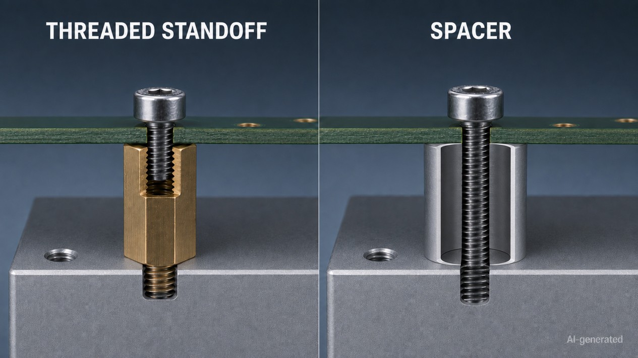
A threaded standoff is a standoff that uses internal threads, external threads, or both to provide mechanical attachment in addition to maintaining separation. It provides spacing and forms part of the threaded connection. A spacer is usually an unthreaded sleeve with a clearance hole. It controls the distance between components while a separate screw or bolt passes through it and supplies the clamping force.
That distinction sounds simple, but supplier terminology is not always consistent. Products described as "threaded spacers" are often functionally standoffs, while some PCB standoffs use snap-in features rather than machine threads. The product drawing and intended load path are therefore more reliable than the catalog name.
This guide explains how threaded standoffs and spacers differ, how each one works and which design is better suited to a particular assembly.
1. What Is a Threaded Standoff?
A threaded standoff is a fixed-length separator with one or more threaded attachment points. It positions two components at a controlled distance while allowing them to be fastened directly to the standoff.
Common thread configurations include:
- Female-female: internal threads at both ends;
- Male-female: an external thread at one end and an internal thread at the other;
- Male-male: external threads at both ends.
In a typical PCB assembly, a male-female standoff screws into a tapped enclosure base. The circuit board rests on the upper face, and a machine screw passes through the PCB into the female thread. The standoff body establishes the mounting height, while its threaded ends secure the surrounding components.
A threaded standoff may perform several functions at once:
- maintain a precise gap;
- support a PCB, plate or sensor;
- provide a removable mounting point;
- reduce the number of loose fasteners;
- align stacked components;
- transfer mechanical load;
- provide an electrical path or controlled isolation.
Hex standoffs are especially common because their wrench flats allow the installer to restrain the body while tightening a mating screw.
2. What Is a Spacer?
A spacer is usually an unthreaded tube, sleeve or collar installed around a screw or bolt. The fastener passes through the spacer and clamps the surrounding components together.
A simple spacer joint may contain:
- a screw head;
- an upper panel or PCB;
- an unthreaded spacer;
- a lower panel or bracket;
- a nut or tapped base.
The spacer determines the gap between the upper and lower components. The screw or bolt supplies the joint preload and keeps the complete stack together.
Most spacers have a smooth clearance hole that is larger than the fastener's nominal diameter. This allows the screw to pass through without engaging the spacer.
Spacers are useful when:
- one long fastener can pass through the complete assembly;
- threading inside the separating component is unnecessary;
- the joint should be clamped as a single stack;
- a simple and economical distance sleeve is preferred;
- slight assembly clearance is needed around the fastener.
Although round tubular spacers are most common, hexagonal and square versions are also available. The outside shape does not determine whether the component is a spacer or a standoff - the presence and function of the threads do.
3. Threaded Standoff vs Spacer: Key Differences
The practical differences are summarized below.
| Comparison point | Threaded standoff | Spacer |
|---|---|---|
| Internal hole | Threaded at one or both ends | Usually smooth and unthreaded |
| External thread | May have one or two male threads | Normally none |
| Main function | Provides spacing and threaded attachment | Provides spacing within a through-fastened joint |
| Fastening method | Screws into or accepts mating hardware | Separate screw or bolt passes through the body |
| Typical configurations | Female-female, male-female or male-male | Clearance-hole sleeve |
| Assembly retention | Can remain attached to one component during service | Usually loose until the complete joint is clamped |
| Part count | Can replace a separate nut, stud or screw in some assemblies | Usually requires a longer screw or bolt and a nut or tapped base |
| Stacking capability | Male-female types can be stacked directly | Multiple spacers must usually be aligned around one fastener |
| Installation access | Can support staged or modular assembly | Requires access along the through-fastener path |
| Typical applications | PCBs, control panels, sensors, enclosures and stacked modules | Through-bolted panels, brackets, shafts and structural stacks |
Industry guides commonly use the same practical distinction: a standoff has threaded attachment features, while a spacer generally allows a separate fastener to pass through its unthreaded bore. However, catalog terminology still varies, so the drawing remains the final authority.
4. How the Load Path Changes
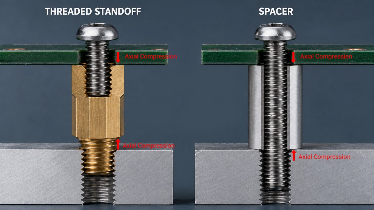
The most important engineering difference is not appearance. It is how the load travels through the joint.
Load Path Through a Threaded Standoff
In a threaded standoff assembly, mechanical loads pass through:
- the mating screw or tapped component;
- the internal or external threads;
- the standoff body;
- the opposite threaded interface.
The threaded interfaces transfer axial loads and maintain the connection, while the standoff body mainly carries compression and bending loads. A tall, slender standoff may be more sensitive to lateral loading than a shorter part with the same thread size.
A male-female standoff also creates two separately assembled interfaces. The lower thread can remain installed while the upper component is removed for maintenance.
Load Path Through a Spacer
In a spacer assembly, the screw or bolt normally runs through the complete stack. The fastener provides tensile preload, while the spacer acts as a compression member between the supporting surfaces.
When tightened correctly, the joint clamps the components and spacer together. The spacer must therefore resist crushing, buckling or permanent deformation under the applied preload.
For plastic spacers, creep can gradually reduce the clamp condition. For thin-walled metal spacers, excessive torque can deform the ends or collapse the sleeve.
Which One Is Stronger?
Neither component is automatically stronger simply because it is threaded or unthreaded.
Strength depends on:
- body diameter and wall thickness;
- material and heat treatment;
- thread engagement;
- fastener size and grade;
- joint preload;
- supporting-face area;
- load direction;
- body length;
- vibration and shock;
- installation quality.
A correctly designed through-bolt and metal spacer can form a highly reliable joint. A poorly engaged threaded standoff can fail despite looking more substantial. Threads are useful, but they are not a substitute for joint design.
5. When Should You Use a Threaded Standoff?
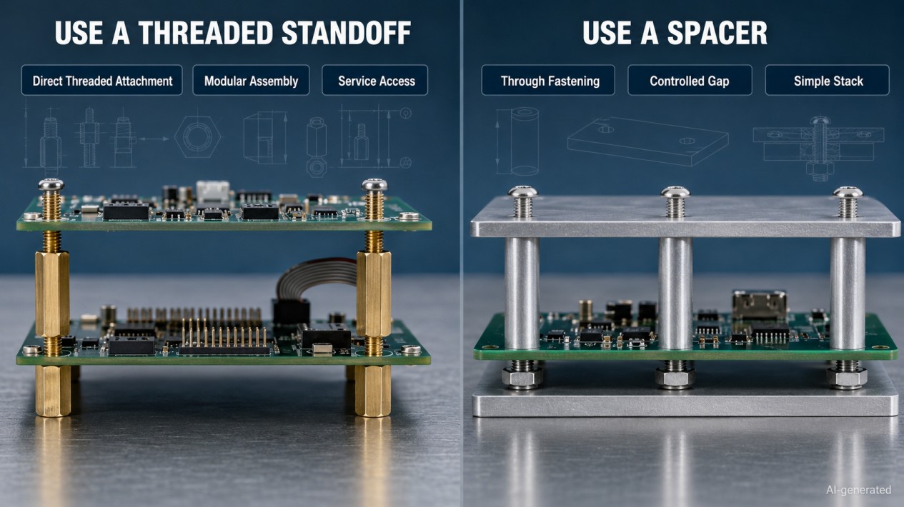
Choose a threaded standoff when the assembly benefits from built-in threaded attachment points.
PCB and Electronic Assemblies
Threaded standoffs are commonly used to mount a circuit board above an enclosure floor or chassis plate. They provide clearance for solder joints, components, cables and airflow while allowing the PCB to be removed independently.
A male-female configuration is particularly useful when the base already contains a tapped hole. A female-female standoff works well when removable screws are required on both sides.
Stacked Boards and Modular Equipment
Male-female standoffs can be screwed into one another to create multiple mounting levels. This makes them practical for:
- stacked PCBs;
- controller modules;
- display assemblies;
- instrumentation;
- prototype systems;
- modular test equipment.
Each level can be installed separately instead of trying to align several loose spacers around one long screw.
Control Panels and Enclosures
Hex standoffs are useful for mounting terminal boards, sensor interfaces and auxiliary plates inside control enclosures. Their wrench flats simplify controlled tightening and later servicing.
Sensors and Precision Brackets
A threaded standoff can establish a defined sensor or bracket height while providing attachment points at both ends. Where positioning accuracy matters, check body-length tolerance, end-face quality and bending stiffness - not only the nominal thread size.
Assemblies Requiring Fewer Loose Parts
A male-female standoff can combine the functions of a screw, spacer and nut. Reducing loose hardware can make production and maintenance easier, especially in compact equipment where a dropped nut tends to explore the least accessible corner available.
6. When Should You Use a Spacer?
Choose a spacer when the assembly needs a controlled gap but does not require threads inside the separating component.
Through-Bolted Assemblies
A spacer is a natural choice when one screw or bolt passes through the entire stack. Examples include:
- parallel mounting plates;
- guards and brackets;
- equipment frames;
- display mounts;
- covers and housings;
- structural panel assemblies.
The spacer maintains separation while the through-fastener clamps the joint.
Simple, Economical Spacing
An unthreaded spacer is generally simpler to manufacture than a standoff with precision internal or external threads. It can be a practical option for high-volume products when the assembly already requires a through-bolt.
Cost should still be evaluated at the assembly level. A cheaper spacer may require a longer screw, separate nut and additional installation time.
Assemblies Requiring Clearance Around the Fastener
The spacer bore can provide clearance around the screw, allowing easier insertion and some accommodation for positional tolerances. The available movement depends on the difference between the spacer bore and fastener diameter.
This clearance can help assembly, but too much clearance may reduce positional control.
Compression-Controlled Joints
A rigid spacer can prevent a screw from crushing a soft enclosure wall, PCB or plastic housing. Instead of allowing the fastener to compress the surrounding material excessively, the spacer forms a controlled compression stop.
In this role, the spacer length and end-face condition are critical.
7. Size and Dimension Differences
Both parts are selected by body length and outside size, but the internal dimensions are specified differently.
Threaded Standoff Dimensions
Check:
- internal and external thread size;
- thread pitch or threads per inch;
- body length;
- male thread length;
- usable female thread depth;
- outside diameter or width across flats;
- thread tolerance;
- body-length tolerance;
- supporting-face dimensions.
For metric hardware, a designation such as M3 x 0.5 identifies a 3 mm nominal thread diameter with a 0.5 mm pitch. Metric and inch threads that look similar should never be treated as interchangeable. Standards such as ASME B1.13M define the general M-profile metric thread system.
Spacer Dimensions
Check:
- inside diameter;
- outside diameter;
- body length;
- wall thickness;
- length tolerance;
- inside-diameter clearance;
- end-face flatness and squareness;
- surface finish.
The spacer inside diameter is normally larger than the screw diameter because it is a clearance hole rather than a mating thread.
Body Length
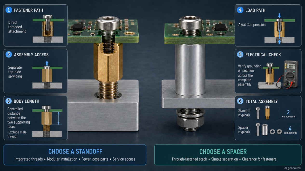
For both components, body length normally refers to the distance between the two supporting faces. A projecting male thread on a standoff is generally excluded.
This distinction matters. A male-female standoff with a 10 mm body and a 6 mm male thread provides approximately 10 mm of controlled spacing - not 16 mm.
If a drawing does not make the supporting faces clear, confirm the dimension before approving the part. The thumbnail is a useful introduction, not a dimensional contract.
8. Materials, Grounding and Insulation
Threading is not the only selection factor. Both standoffs and spacers are available in metal and engineering plastics.
| Material | Main advantages | Important considerations |
|---|---|---|
| Brass | Good machinability, reliable threads and electrical conductivity | Weight, strength, plating and galvanic compatibility |
| Stainless steel | High strength and corrosion resistance | Cost, weight and possible thread galling |
| Carbon steel | Good strength and cost efficiency | Protective finish and corrosion exposure |
| Aluminum | Low weight and good machinability | Thread wear and galvanic interaction |
| Nylon or engineering plastic | Electrical insulation, low weight and corrosion resistance | Creep, temperature, moisture and lower stiffness |
A metal standoff may form part of an electrical bonding path, but conductivity should not be assumed. Paint, anodizing, plating, washers and surface contamination can interrupt the connection.
A metal spacer around a metal screw can also create a conductive path. Conversely, a nylon spacer does not guarantee complete electrical isolation if the through-fastener remains conductive.
The full assembly must therefore be evaluated for:
- grounding continuity;
- creepage and clearance;
- corrosion;
- operating temperature;
- moisture and chemicals;
- continuous clamp load;
- repeated assembly cycles.
Material type alone does not define the electrical or mechanical behavior of the completed joint.
9. Can a Spacer Replace a Threaded Standoff?
Sometimes, but not as a direct one-for-one substitution.
Replacing a standoff with a spacer normally requires changes to the fastening system. The new assembly may need:
- a longer screw or bolt;
- a nut or tapped base;
- access to the opposite side;
- additional washers;
- a different installation sequence;
- more clearance for the fastener head;
- a revised grounding or insulation strategy.
The substitution can also change the load path. A standoff transfers loads through its threaded ends, while a spacer is normally compressed inside a through-fastened stack.
Replacing a spacer with a threaded standoff creates similar questions. The designer must confirm that:
- the surrounding components can accept the new threads;
- the thread configuration matches the assembly order;
- sufficient thread engagement is available;
- the standoff faces provide adequate support;
- tool access is available;
- the new part does not create an unintended conductive path.
A product called a threaded spacer may already be a standoff in functional terms. Before changing anything, inspect the drawing for internal or external threads and identify exactly how the part is retained.
10. How to Choose Between a Standoff and Spacer
Use the following process instead of choosing by appearance.
Identify the Fastener Path
Ask whether one screw or bolt can pass through the complete assembly. If yes, an unthreaded spacer may provide the simplest arrangement. If the components must be installed separately, a threaded standoff may be more practical.
Review Assembly Access
Determine which sides are accessible during installation and maintenance. A male-female standoff can be installed into a tapped base before the upper component is added. A spacer usually remains loose until the through-fastener is inserted and tightened.
Define the Required Gap
Calculate the required body length using the complete dimensional stack, including component height, connector and cable clearance, airflow, electrical clearance, enclosure dimensions, panel thickness, manufacturing tolerances, and expected deflection.
Evaluate the Loads
Consider compression, tension, shear, bending, shock, vibration, and repeated servicing. Do not assume that a threaded standoff is automatically better for vibration. Reliable performance depends on preload, thread retention, bearing surfaces, material stiffness and the overall joint design.
Check Fastener Compatibility
For a standoff, verify thread diameter, pitch, configuration, male thread length and female thread depth. For a spacer, verify bore clearance, screw length, outside diameter and available bearing area.
Select Material and Finish
Balance strength and stiffness, corrosion resistance, weight, conductivity or insulation, temperature, appearance, cost, and expected service life.
Review Production and Maintenance
Consider the complete assembly cost rather than only the component price. A standoff may cost more per part but reduce the number of loose fasteners. A spacer may be less expensive but require a longer bolt, separate nut and additional handling.
Validate the Assembly
Prototype the real stack and check spacing, alignment, clamp condition, screw engagement, access for tools, electrical continuity or isolation, resistance to vibration, and ease of disassembly. The best component is the one that works in the complete assembly, not the one with the most attractive catalog description.
11. Common Selection Mistakes
The most common mistake is treating a standoff or spacer as an isolated part. Both belong to a fastening system, and their performance depends on the components around them.
| Mistake | Likely result | Better approach |
|---|---|---|
| Assuming every hexagonal separator is a standoff | Incorrect fastening method | Inspect the internal bore for threads |
| Treating "threaded spacer" as a separate universal product type | Catalog confusion | Classify the part by its actual thread configuration |
| Using total length instead of body length | Incorrect mounting height | Identify the two supporting faces |
| Selecting a spacer bore equal to the screw diameter | Difficult or impossible assembly | Use the required clearance-hole diameter |
| Ignoring female thread depth | Screw bottoms before clamping | Calculate screw penetration through the complete stack |
| Assuming a spacer is structurally weak | Unnecessary redesign | Evaluate the actual material, geometry and joint preload |
| Assuming a standoff is always better under vibration | Loosening or thread failure | Validate preload and retention at every interface |
| Selecting plastic without checking creep | Loss of clamp force or spacing | Verify continuous load and operating temperature |
| Assuming metal hardware guarantees reliable bonding | Unreliable electrical connection | Test continuity after finishing and assembly |
| Comparing component price alone | Higher total assembly cost | Include fasteners, labor, tooling and maintenance |
FAQ about Threaded Standoff vs Spacer
Q: What is the main difference between a threaded standoff and a spacer?
A threaded standoff contains internal threads, external threads or both, allowing it to form part of the fastening connection. A spacer is usually an unthreaded sleeve through which a separate screw or bolt passes.
Q: Are all standoffs threaded?
Not necessarily. In general mechanical-hardware terminology, standoffs are commonly threaded. However, snap-in, push-fit and other PCB supports may also be described as standoffs even though they do not use machine threads.
Q: Are spacers always unthreaded?
Conventional screw spacers are normally unthreaded. If the body contains a functional internal or external thread, it is more accurately treated as a threaded standoff, regardless of the catalog name.
Q: Which is stronger: a standoff or a spacer?
Neither is inherently stronger. Strength depends on material, body diameter, wall thickness, thread engagement, fastener size, joint preload and load direction.
Q: Can a spacer be used with a tapped hole?
Yes. A screw can pass through the spacer and engage a tapped hole in the base. The spacer remains unthreaded and controls the distance between the mounted component and the base.
Q: Does a threaded standoff require two screws?
Not always. A female-female standoff normally accepts screws at both ends. A male-female standoff has its own external thread at one end and usually requires only one separate screw at the other.
Q: Can standoffs and spacers provide electrical insulation?
They can when made from a suitable insulating material, but the complete fastener path must be considered. A nylon spacer around a metal screw may not electrically isolate the two mounted components.
Q: Is a hex spacer the same as a hex standoff?
No. Both may have hexagonal bodies, but a hex spacer normally has an unthreaded clearance hole, while a hex standoff contains internal or external threads.
Conclusion: Threaded Standoff vs Spacer
The difference between a threaded standoff and a spacer comes down to how each component participates in the joint.
A threaded standoff provides controlled spacing and one or more threaded attachment points. A spacer primarily provides controlled spacing while a separate screw or bolt passes through it and clamps the assembly.
Use a threaded standoff when modular installation, direct threaded attachment, reduced loose hardware or repeated servicing matters. Use a spacer when a through-fastened stack offers a simpler and more economical solution.
Neither option is universally better. The correct choice depends on the load path, dimensions, assembly sequence, material and service environment. When the catalog terminology becomes vague - as it occasionally does - trust the drawing. Hardware names can improvise; dimensions generally cannot.
Explore threaded standoffs and hex standoff spacers available through JLCMC for different thread sizes, materials, body lengths and assembly configurations.
Popular Articles
Keep Learning
Indexing Plunger Selection Guide: Engagement Depth, Reset Mechanism, and Load Paths
Key Takeaways Reset behavior and retention in the retracted position describe operation, not the pin's load capacity. Confirm engagement at the receiving feature rather than relying only on the knob position. Check the minimum available straight engagement after mounting gaps and lead-in geometry are included. Spring force acts along the pin; transverse holding loads also involve the pin, guide, mounting structure and receiving hole. Reduce unnecessary unsupported distance and assess bending where the......
How to Remove a Stripped Hex Socket Screw (Allen Screw)
A stripped Allen screw becomes hard to remove when the hex key no longer grips the socket. The recess might have rounded edges, or rust might hold the thread in place. Before you use force, check what part has damage. The right method depends on whether the problem sits in the socket or deeper in the thread. If you want to remove a stripped hex screw, start with the least harsh method. Clean the socket and test the exact key size first. Move to pliers or an extractor only if simple methods fail. A slo......
How to Remove a Stripped Torx Screw
A stripped Torx screw has a damaged star-shaped recess. Your bit slips, turns inside the head, or fails to grip. Do not start with more force. Extra force often damages the recess further. People removing stripped Torx screws should start with the simplest method first. Clean the recess. Check the bit size. Add steady downward pressure. Move to extraction tools only when basic steps fail. Diagnose the Problem Before Applying More Force A damaged screw head is only one possible problem. Before removing......
What Is a Hex Screw? Hex-Head and Hex-Socket Fasteners Explained
If you ask what is a hex screw, the answer depends on the type of drive. Some people use the term for a screw with an outer six-sided head. Others use it for a screw with a six-sided recess inside the head. Both forms use a hex shape, but the tool sits in a different place. An external hex head works with a wrench or socket. An internal hex socket works with a hex key, also called an Allen key. The right term depends on the fastener standard and the product name used by the maker. Hex Screw Definition......
Understanding Different Types of Hex-Head Screws
Hex socket screws use a six-sided recess inside the head. You turn them with a hex key or hex bit. The basic drive stays similar across the range, but the head shape and screw form change from one type to another. These differences affect head clearance, surface contact, and the role of the screw in the joint. People often group all hex screw types under one name. A socket head cap screw does not serve the same role as a set screw or shoulder screw. You should check the head profile and thread layout ......
Types of Hex Bolts and How to Choose Them
Hex bolts have a six-sided head that fits a wrench or socket. People use them in many joints because the head gives the tool broad contact and easy access. The main differences come from thread length, thread pitch, head form, material, and finish. The types of hex bolts also vary by standard and job. A partially threaded bolt suits one kind of joint, while a fully threaded hexagon-head screw suits another. You should look at the full joint before you choose a fastener. Hex Bolt Types at a Glance The ......