Two-Hole Locating Pin Design Guide: Round and Diamond Pin Tolerance Principles
10 min
- Give Each Locator a Defined Job
- Why Two Round Pins Can Bind
- Orient the Relief Along the Hole-Center Line
- Understand What Clearance Does to Orientation
- Compare Practical Layout Choices
- Separate Lead-In Geometry from the Locating Surface
- Reviewing JLCMC Round and Polygonal Candidates
- Validate the Fixture With Representative Parts
- FAQ about Two-Hole Locating Pin Design
Key Takeaways
- Once the part is supported on its primary surface, the locating layout must control its in-plane position and rotation.
- Two close-fitting round pins can demand incompatible hole spacing and make loading difficult.
- A correctly oriented relieved secondary pin accommodates variation along the line between holes while controlling movement across that line.
- More clearance can ease assembly but also changes possible position and angular variation.
- Lead-in shape, locating cross-section and mounting shank are separate design features.
- Verify a product's actual cross-section and tolerances; a polygonal label alone does not establish diamond-pin behavior.
A removable plate fits over two pins during a workshop trial, then binds when a different production part arrives. Both holes can be within their diameter limits while their spacing differs enough to prevent the plate from seating. The problem is often the relationship between the locating features, rather than a visibly defective pin.
A two-hole fixture should locate the workpiece without demanding more geometric precision than the manufacturing process can deliver. In standard tooling design using components like JLCMC locating pins, the classic 3-2-1 locating method pairs a cylindrical primary pin with a directionally relieved secondary pin (diamond pin). This design guide details the constraint mechanics, tolerance calculation, and relief alignment required to prevent jamming.
Give Each Locator a Defined Job
Consider a rigid plate resting on a defined support surface. In a simplified planar model, it can still move in two directions across that surface and rotate around an axis normal to it.
A round pin entering the first hole establishes the primary in-plane position, subject to the actual fit clearance. The part can still turn about that primary location. A secondary locator, spaced away from the first, controls that remaining orientation.
The secondary feature does not need to establish the distance to the first hole again if the primary location and part geometry already determine it. Requiring another close fit in that direction creates a redundant demand. Under standard fixture design principles (the 3-2-1 locating principle and DIN/ISO jig design standards), pairing a round primary pin with a relieved diamond pin restricts the remaining rotational degree of freedom without introducing overconstraint or binding.
Keep the support and clamping functions explicit. Locating pins determine position through their contact geometry; clamps seat and retain the part against the intended supports. A clamp should not be used to force an incompatible two-pin layout into place. That can distort a thin plate and make the apparent fit dependent on clamp force.
Why Two Round Pins Can Bind
Hole diameter and hole-center spacing are separate dimensions. A small diametral clearance around each pin may be enough for an individual hole to load easily, yet insufficient for the combined spacing mismatch.
For an illustrative pair of actual measured features, suppose both holes are 10.02 mm in diameter and both round pins are 10.00 mm. Each hole has 0.02 mm diametral clearance, equivalent to 0.01 mm radial clearance.
Ignoring form error, angular misalignment and elastic deformation, the two radial clearances can together accommodate at most 0.02 mm of center-distance mismatch along the line between the holes. If the measured pin spacing and hole spacing differ by 0.06 mm, the plate cannot simply translate into a compatible position. Enlarging an entrance chamfer may make initial entry easier, but the interference remains when the cylindrical portions engage.
This is a geometry example, not a recommended fit or a JLCMC dimension. A real tolerance analysis must include the limits of both hole and pin diameters, their positions, relevant form errors and the assembly's operating conditions. Temperature differences can also change the relationship between features on dissimilar materials or differently heated parts.
Orient the Relief Along the Hole-Center Line
Imagine the line joining the two hole centers as the X direction. The secondary locator should allow the required difference in X while controlling displacement in the perpendicular Y direction. Its effective locating contact therefore acts across the hole-center line, limiting rotation about the primary round pin.
The direction of relief is critical. Rotating a relieved pin incorrectly can leave the spacing conflict in place while loosening the direction that was supposed to control orientation. Describe the required constrained and relieved directions on the fixture drawing rather than relying on the visual impression of a “diamond” shape.
Standard fixture tolerance design principles establish that a round-and-diamond pin configuration specifically accommodates center-to-center distance variation between mounting holes. The diamond pin's relieved flats must be oriented precisely parallel to the centerline connecting the two hole centers, allowing bilateral thermal and manufacturing tolerance float while maintaining zero rotational play across the perpendicular axis.
Also check how the secondary pin's orientation is established and maintained in the fixture. A design that depends on direction must retain that direction after installation, replacement and service. Record a datum or orientation feature that can be checked without guessing from an inaccessible pin tip.
Understand What Clearance Does to Orientation
Directional relief solves a spacing conflict; it does not remove clearance in the direction that locates the part. The primary round fit and the secondary transverse fit still permit some movement. The distance between locators influences how that movement translates into angular variation.
For a small angle, a useful planning relationship is:
Angular variation in radians ≈ relative transverse displacement ÷ locator spacing.
Suppose a simplified clearance assessment permits 0.02 mm of relative transverse displacement between the two locating positions, which are 100 mm apart. The corresponding angular variation is approximately 0.0002 radians, or 0.011 degrees. At a feature 150 mm from the primary location, that rotation alone contributes approximately 0.03 mm of lateral movement.
The assumed 0.02 mm is the relative displacement from the chosen clearance analysis, not an automatically applicable pin tolerance. Primary-locator translation, hole-position errors, part flexibility and support condition can add other contributions. Use the example to connect the fixture layout to the feature being inspected or assembled, not to claim a complete accuracy result.
Longer locator spacing can reduce the angular effect of a given transverse displacement, but the layout must still suit the part's datum scheme, stiffness and accessible holes. Moving locators farther apart is not a substitute for checking those requirements.
Compare Practical Layout Choices
| Layout | What it can provide | Main limitation | Drawing check |
|---|---|---|---|
| Two close-fitting round pins | Location where the complete fit relationship is controlled | May bind on spacing mismatch | Worst-case combined hole/pin spacing and clearance |
| Round primary plus correctly relieved secondary | Position and orientation with directional spacing accommodation | Relief has finite range and must be oriented correctly | Retained locating width, relieved width and orientation |
| Round primary plus suitable floating secondary | Controlled location with additional accommodation in one direction | More components and a defined travel range | Fixed direction, floating direction and travel limits |
| Round primary plus a loose round secondary | Easier assembly with larger clearance | Extra clearance affects orientation in multiple directions | Permitted angular variation and resulting feature error |
A diamond pin is appropriate for standard center-distance tolerances. When spacing variation exceeds the clearance provided by diamond pin reliefs, fixture design standards specify floating locating pins or slotted bushings with spring-loaded or sliding blocks. Select the mechanism based on worst-case tolerance stack-up analysis rather than arbitrarily increasing pin clearance by trial and error.
Separate Lead-In Geometry from the Locating Surface
A conical or rounded tip can guide the part during loading, while a different section below it performs the final location. The tip should not be confused with the effective locating cross-section.
Check the heights of both pins against the intended insertion sequence and part thickness. In standard fixture engineering, designing a deliberate step height between the primary and secondary pins (with the round primary pin standing taller) allows the workpiece to engage the primary datum first before aligning with the secondary pin. This staged engagement prevents wedging, provided the workpiece does not tilt excessively during loading.
Once seated, the part should rest on its intended supports and engage the required locating sections. Burrs around a hole, chips on a support, or a lead-in sitting against the wrong surface can produce inconsistent seating even when the nominal pin diameters are correct.
Reviewing JLCMC Round and Polygonal Candidates
JLCMC lists the FDXE positioning-pin family with a round insertion surface, a conical insertion head, a large-head form and a straight mounting shank. Those family attributes make it relevant when reviewing a round primary locator; the selected size and fit still need to match the drawing.
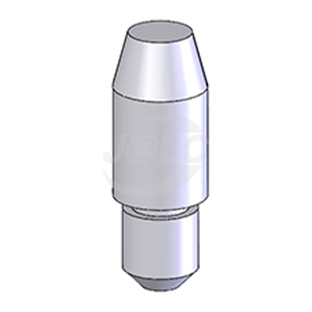
JLCMC FDXE family image. Lead-in shape and locating diameter serve different purposes.
The related FDXF family specifies a polygonal insertion surface. Treat it as a candidate requiring a cross-section review. The word “polygonal” and the product photograph alone do not confirm the retained locating width, amount of relief or allowable displacement needed for a particular round-and-diamond layout.
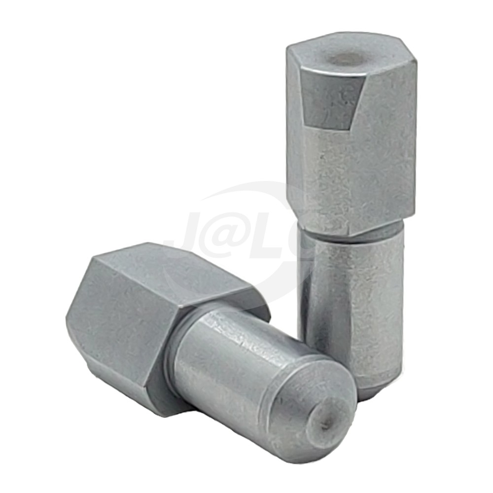
JLCMC FDXF family image. Confirm the chosen variant's geometry before assigning it a directional locating function.
For either family, obtain the selected variant's locating dimensions, mounting dimensions, tolerances, useful engagement length and relevant material information. For a secondary relieved locator, explicitly compare its section with the required constrained and free directions. Do not assume two families form a qualified matched pair simply because their names are similar.
Validate the Fixture With Representative Parts
Check loading and unloading using parts that represent the allowed hole sizes and positions. Inspect seating at the primary supports before applying the clamps, and confirm that clamping does not pull a partly seated part into place.
Repeat the location measurement after several removal-and-replacement cycles using the intended operator sequence. Examine the feature that matters to the process, not only the fit at the pins. A plate may feel easy to load yet rotate enough to move a distant connector or inspection feature beyond its required position.
Record the pin identities, installed orientation, support condition and observed results. Recheck these after replacing a locator or changing the workpiece drawing. A replacement with the correct nominal diameter can still have the wrong relief orientation or useful locating length.
FAQ about Two-Hole Locating Pin Design
Must every two-hole fixture use a diamond pin?
No. Other layouts can work when the complete geometry and tolerance relationship support them. A round-and-relieved pair is a common way to avoid redundant spacing constraint.
Which direction should a diamond pin relieve?
For the common arrangement described here, it accommodates variation along the line between the hole centers and controls displacement perpendicular to that line. Verify the actual cross-section and installation orientation.
Can I solve binding by enlarging both holes?
More clearance may permit assembly, but it changes possible translation and rotation. Evaluate the resulting location error before changing the workpiece or fixture.
Does a tapered tip guarantee accurate final positioning?
No. A tip can assist entry while final location depends on another section. Check where contact occurs when the part is fully seated.
Can any polygonal pin replace a diamond locator?
No. Its effective contact directions and dimensions must provide the required constraint and relief. A product-family shape label is insufficient evidence.
Should clamps correct a tight fit over the pins?
Clamps should seat the part against the intended supports. Investigate incompatible geometry, contamination or misalignment before using clamping force to overcome loading resistance.
Conclusion: Two-Hole Locating Pin Design
A reliable two-hole layout assigns a clear job to each locator. Establish primary position, control orientation, and leave enough accommodation for permitted spacing variation. Use the tolerance analysis to specify the secondary relief, then verify the actual product geometry and fixture behavior with representative parts.
Popular Articles
Keep Learning
Polyurethane Bumper Energy Calculation: Impact Kinetic Formulas, Stroke & Duty Cycles
Key Takeaways Impact energy depends on contact velocity squared, so a small speed change can materially alter the stopping event. Physical bumper height is not the same as permitted compression or usable stopping distance. Include work from a drive force that continues during compression, plus gravity or rotational effects where applicable. Hardness describes indentation resistance; it is not an energy rating or a complete force-deflection curve. Repeated impacts require a duty assessment as well as a......
Rubber Vibration Isolator Natural Frequency Calculation & Rigid Bypass Troubleshooting Standards
Key Takeaways Trace every mechanical connection between the isolated assembly and its surroundings, including services and guards. Compression, shear and tension are different loading conditions; use the data for the intended direction. A mount must be loaded appropriately, not merely kept below its maximum capacity. Keep deliberate retention hardware compatible with the movement needed for isolation. Compare vibration before and after changes at consistent operating conditions and measurement locatio......
What Is a Torx Screw? Star Drive and Security Torx Explained
If you have seen a screw with a six-point star recess, you have likely seen a Torx screw. So, what is a Torx screw? It is a screw with a six-lobe drive profile. You use a Torx bit to turn the screw. People often call this shape a star drive because of its six-lobe form. The standard Torx profile has six smooth, round lobes rather than sharp points. Other six-lobe drive profiles may look similar, but their dimensions can differ, and their tools may not be interchangeable. This shape gives the tool broa......
How to Drill Out a Stripped Screw Safely?
A stripped screw often turns a simple repair into a hard job. The driver slips because the screw recess no longer gives the bit a firm grip. A broken head or rusted screw creates a similar problem. Drilling screws out should come after simpler removal methods fail. Your goal is to remove enough metal to free the screw head without harm to the part. Good control matters more than force. A drill bit that moves off center might damage the hole or nearby surface. Start with a small bit and keep the drill ......
How to Remove a Stripped Hex Bolt: 7 Effective Removal Methods
A stripped hex bolt loses enough tool contact that a normal hex key or socket slips under force. The damage might affect an internal hex recess or the outer bolt head. Rust can make the problem worse because the thread then needs more force to turn. The safest stripped hex bolt removal method starts with a damage check. Use the least harsh option first, then move to stronger methods only if needed. Your main goal is to remove the bolt without harm to the thread or nearby part. What Is a Stripped Hex B......
Self-Drilling vs Self-Tapping Screws: What Is the Difference?
People often treat self-drilling and self-tapping screws as the same fastener. The two terms have a close link, but they do not mean the same thing. A self-tapping screw forms or cuts its own matching thread as you drive the screw into a suitable base material. Depending on the screw design and material, some self-tapping screws need a pre-drilled pilot hole, while others can be installed directly. A self-drilling screw is a type of self-tapping screw with a drill point at the tip, which drills the ho......