Ball Nose End Mill Stepover: Scallop Height and Effective Diameter
10 min
- What Stepover Actually Controls
- Calculate an Initial Scallop Height
- Why Scallop Height Is Not the Same as Ra
- Effective Cutting Diameter: The Second Calculation
- Match the Strategy to the Surface
- Selecting a JLCMC Ball Nose Tool
- A Practical First-Part Validation Sequence
- FAQ about Ball Nose End Mill Stepover
Key Takeaways
Geometric Control: Stepover directly controls geometric scallop height, but it does not automatically guarantee a measured Ra value.
Cusp Height Formula: For a ball radius $R$ and pass spacing $s$ on a flat surface, the ideal cusp height is $h = R - \sqrt{R^2 - \frac{s^2}{4}}$.
Tool Radius Advantage: A larger ball can use wider spacing for the same ideal cusp, provided it can reach the required geometry without gouging.
Effective Diameter: The active cutting diameter near the tool tip can be significantly smaller than the nominal diameter, leading to lower cutting speed.
Practical Factors: Surface slope, stock allowance, runout, tool deflection, and CAM tolerance can dominate the final surface finish.
Validation: Always test representative shallow and steep regions before applying a single strategy to an entire part.
A ball nose end mill can follow a curved surface, yet still leave visible ridges after finishing. Those ridges do not automatically mean the cutter is dull. Every neighboring tool pass leaves a geometric cusp, and the distance between passes determines how high that cusp becomes.
The useful question is therefore more specific than “What percentage stepover should I use?” Start with the surface requirement, calculate an initial pass spacing, and then check whether the tool is actually cutting at the diameter assumed in the speed calculation. This guide separates those decisions and shows how to verify them before committing to a long finishing cycle.
What Stepover Actually Controls
Imagine taking a cross-section perpendicular to two parallel finishing passes. Each pass leaves a circular envelope. Their intersection produces a small ridge between the paths. Reducing the separation lowers that ridge, but it also increases the number of passes needed to cover the surface.
In the geometric model, $s$ represents the actual spacing between adjacent tool paths in the cross-section being evaluated. A CAM system may define stepover differently, such as a planar XY distance, surface distance, or a value calculated from a scallop-height target. Do not substitute a CAM stepover value into the equation without confirming how the software defines it.
A regular pattern of ridges at the programmed spacing is consistent with scallops. Irregular tearing, isolated scratches, or periodic marks unrelated to pass spacing suggest additional causes. Reducing stepover may make the regular ridges smaller while leaving those other defects unchanged.
Calculate an Initial Scallop Height
For ideal parallel passes over a flat plane, using a spherical tool of radius $R$:
$$h = R - \sqrt{R^2 - \frac{s^2}{4}}$$
Here, $h$ is the cusp height and $s$ is the pass spacing. Use the same length unit for every term. This is a geometric relationship derived from the right triangle between a tool center, the midpoint between passes, and the intersection of the circular envelopes.
If the desired cusp height is known, rearrange it:
$$s = 2\sqrt{2Rh - h^2}$$
Quick Approximation Formula
For small cusps relative to the tool radius, $h \approx \frac{s^2}{8R}$ is a useful approximation. The exact expression is simple enough for a spreadsheet, so use it when creating a setup sheet. Neither expression includes cutting-edge wear, machine motion error, or material deformation.
Worked Example: A 6 mm Ball End Mill
Assume a 6 mm diameter ball, so $R = 3\text{ mm}$. This is a calculation example, not a cutting recommendation or a statement about a particular JLCMC size.
| Pass Spacing $s$ | Percentage of Nominal Diameter | Ideal Cusp Height $h$ |
|---|---|---|
| 0.20 mm | 3.3% | 0.00167 mm (~1.67 µm) |
| 0.40 mm | 6.7% | 0.00667 mm (~6.67 µm) |
| 0.60 mm | 10.0% | 0.01504 mm (~15.04 µm) |
| 0.80 mm | 13.3% | 0.02679 mm (~26.79 µm) |
When the stepover is small relative to the ball radius, doubling the stepover approximately quadruples the geometric cusp height. Conversely, halving it roughly doubles the pass count for the same area and path direction. Actual cycle time also depends on linking moves, acceleration, and feed limits.
If the initial geometric target is 0.005 mm, the exact equation gives $s \approx 0.346\text{ mm}$. That is a starting point for CAM and a test cut. It is not a promise of a 5 µm roughness specification.
Why Scallop Height Is Not the Same as Ra
Scallop height describes the peak-to-valley geometry between ideal paths. Ra is an arithmetic average of profile deviations measured under a defined procedure. They describe different properties, and a single cusp-height number cannot be substituted directly for an Ra requirement.
The direction of measurement matters as well. A trace across the passes encounters the scallops; a trace along a pass captures a different set of features. When a drawing specifies surface texture, preserve its measurement direction, evaluation conditions, and any associated process requirements.
Acceptance Criteria
For a cosmetic cover, appearance under the intended lighting may be part of acceptance. For a sealing or sliding surface, the drawing's functional texture requirements matter more than whether the toolpath looks attractive in simulation. Agree on the actual acceptance method before spending extra machine time on a smaller spacing.
Effective Cutting Diameter: The Second Calculation
Nominal tool diameter is the largest diameter of the ball. A shallow cut near its bottom engages a smaller circle. The outermost engaged circle in a simple, untilted, flat-surface cut can be calculated as:
$$D_{\text{eff}} = 2\sqrt{2Rz - z^2}$$
Let $z$ be the distance from the ball tip to the contact plane, measured along the tool axis, with $0 < z \le R$. This formula is for that defined contact geometry; do not apply it unchanged to a tilted tool or a changing sculpted surface.
For the illustrative 6 mm ball at $z = 0.20\text{ mm}$, $D_{\text{eff}}$ is about 2.154 mm. At the same spindle speed, the peripheral speed corresponding to this local contact diameter is about 36% of the value calculated using the nominal 6 mm diameter. The exact center has zero peripheral speed.
Harvey Performance's ball nose milling guide explains the distinction between nominal and effective diameter and discusses using an incline to avoid cutting at the tool center. Apply its principle with the actual contact geometry; its example settings are not specifications for another manufacturer's cutter.
In metric units, $v_c = \frac{\pi D_{\text{eff}} n}{1000}$, where $v_c$ is in m/min, diameter is in mm, and $n$ is in revolutions per minute. A smaller effective diameter changes the speed calculation. Any resulting spindle-speed adjustment must still respect the cutter, holder, spindle, balance, and machine limits. Recalculate feed consistently rather than changing RPM in isolation.
Match the Strategy to the Surface
| Surface or Constraint | Useful Planning Choice | Main Check |
|---|---|---|
| Broad, shallow surface | Parallel finishing or a cusp-controlled path | Spacing definition and tip contact |
| Steep wall | A strategy that controls spacing over the steep region | Actual surface spacing rather than XY spacing alone |
| Tight concave feature | Smaller ball or a separate rest-finishing operation | Cutter radius, residual stock, and access |
| Mixed shallow and steep regions | Separate operations or suitable adaptive spacing | Transitions, overlaps, and witness marks |
| Deep reach | Shortest practical overhang and verified holder clearance | Deflection and collision envelope |
These are programming choices, not universal rankings. A larger ball may improve coverage on an open surface but cannot enter a concave radius smaller than itself. A smaller ball may reach the detail but require more passes over the broad region. Splitting the work can be more effective than forcing one cutter and one spacing to do both jobs.
Also distinguish finishing stock from toolpath spacing. Stepover determines the distance between passes. Remaining stock determines how much material the cutter meets. A finishing path that crosses uneven roughing remnants can experience varying engagement even when its stepover is constant.
Selecting a JLCMC Ball Nose Tool
The JLCMC LXDC ball nose end mill family is listed as carbide, two-flute, uncoated, and intended for aluminum alloy processing. These verified attributes make it a relevant family to review for aluminum contouring. They do not establish a universal feed, speed, or surface finish.
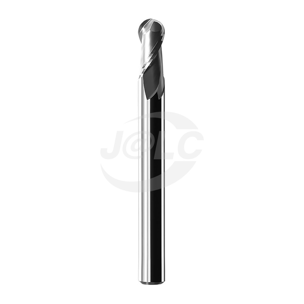
JLCMC LXDC two-flute ball nose end mill, official catalogue image
JLCMC LXDC catalogue image. Select and check the individual part drawing before programming; the illustration does not define the ordered dimensions.
Choose the required radius first, then confirm cutting diameter, shank diameter, flute length, total reach, and holder clearance for the selected part number. Check the exact material and coating match instead of assuming every ball nose family has the same application range. If cutting data for the chosen variant is unavailable, obtain it before turning a geometric example into a machine setup.
A Practical First-Part Validation Sequence
Define Acceptance
Record whether the requirement is dimensional, cosmetic, measured texture, or a combination. Identify the hardest region to inspect and machine.
Calculate the Initial Spacing
Use the exact cusp equation for a simple reference geometry, and record its assumptions.
Inspect the Contact Map
Look at shallow areas, steep walls, small radii, and transitions. Confirm how CAM controls spacing in each region.
Check the Complete Assembly
Include the holder, overhang, fixtures, residual stock, and machine travel in collision review.
Cut a Representative Test
Use the intended material, holder, and stock condition. Evaluate more than the easiest flat patch.
Change One Variable at a Time
If the pattern matches the path spacing, review cusp height. If marks are irregular, inspect runout, rigidity, chips, tool condition, and motion before making the entire program denser.
Save the accepted toolpath and inspection result with the tool assembly information. This makes the result repeatable when the job returns, rather than leaving the next operator with only a percentage stepover and an unexplained RPM.
FAQ about Ball Nose End Mill Stepover
Q: Is 10% stepover always appropriate for a ball nose end mill?
No. A percentage is convenient but hides the tool radius and required surface result. Calculate the geometric cusp, check the actual surface, and validate the process. The example table shows what 10% means for one illustrative diameter.
Q: Does a larger ball always produce a better finish?
For the same spacing on the ideal flat geometry, a larger radius produces a lower cusp. It may also lose access to small features or require a different holder position. Reach and local curvature must be checked before choosing it.
Q: Can I use scallop height directly as my Ra target?
No. They are different quantities. Use scallop height to plan the toolpath, then evaluate the finished surface using the measurement method required by the drawing or process specification.
Q: Why does a shallow area look worse than a steep area?
One possible cause is contact close to the ball center, where peripheral speed is low. Other causes include the path's spacing definition, changing stock, or deflection. Compare the contact geometry and observed marks before changing settings.
Q: Should I increase RPM whenever the effective diameter is small?
Only after checking the tool's cutting recommendations and all equipment limits. Effective diameter informs the calculation; it does not override maximum operating conditions or establish a feed recommendation.
Q: Can a smaller stepover fix chatter?
It may alter engagement, but it does not diagnose or guarantee a solution to chatter. First check the tool assembly, overhang, workholding, cutting conditions, and the pattern of vibration marks.
Conclusion: Ball Nose End Mill Stepover and Scallop Height
Set ball nose stepover from a defined geometric target, then check the actual contact diameter and surface geometry. An exact cusp calculation provides a useful starting point; a representative test cut establishes whether the complete tool, machine, and CAM strategy meet the part requirement.
Popular Articles
Keep Learning
Drawer Slide Selection Guide for Equipment Trays: Sizing, Load Calculation & Locking
Key Takeaways Gross Load First: Calculate the moving assembly's gross load, including the tray, brackets, equipment and attached accessories. Travel, Not Rail Length: Specify the actual travel needed for service access; nominal rail length alone does not establish that travel. Know Your Lock: Distinguish a positive lock, a detent, a soft-close feature and a disconnect mechanism. Three Independent Checks: Treat slide capacity, mounting-bracket strength and cabinet tipping resistance as separate checks.......
Threaded Standoff vs Spacer: What Is the Difference?
Key Takeaways Threaded standoffs provide both spacing and threaded attachment points, making them ideal for modular assemblies and PCBs. Spacers are unthreaded sleeves that work with through-bolts to maintain gaps in clamped assemblies, offering a simpler and more economical solution. The right choice depends on the load path, assembly sequence, material, and service environment - not just appearance or catalog naming. A threaded standoff and a spacer can look almost identical on a workbench. Both cre......
How to Choose a Threaded Standoff for PCB and Mechatronic Assemblies
Key Takeaways Select the right configuration: Choose male-female, female-female, or male-male thread configurations based on the two mating interfaces and the intended assembly sequence. Treat height as a tolerance stack: Standoff body length must satisfy clearance, electrical, thermal, and connector requirements across the full tolerance range, not just the nominal dimension. Verify thread engagement: Check male thread length against tapped-hole depth and upper screw length against usable female thre......
Threaded Standoff Guide: Types, Sizes, Materials and Applications
Key Takeaways Thread configuration first: Choose female-female, male-female or male-male based on how both sides of the assembly attach — thread config is the most practical way to classify a threaded standoff. Body length is the critical dimension: Standoff length refers to the distance between supporting faces, not total physical length. Reading the wrong length causes incorrect mounting height or screw bottoming. Material affects more than strength: Brass, stainless steel, carbon steel, aluminum an......
Ball Nose End Mill Stepover: Scallop Height and Effective Diameter
Key Takeaways Geometric Control: Stepover directly controls geometric scallop height, but it does not automatically guarantee a measured Ra value. Cusp Height Formula: For a ball radius $R$ and pass spacing $s$ on a flat surface, the ideal cusp height is $h = R - \sqrt{R^2 - \frac{s^2}{4}}$. Tool Radius Advantage: A larger ball can use wider spacing for the same ideal cusp, provided it can reach the required geometry without gouging. Effective Diameter: The active cutting diameter near the tool tip ca......
Manual SMT Stencil Printer Sizing: Print Area, PCB Support and Frame Fit
Key Takeaways Different dimensions: Worktable size, effective print area, board envelope, and stencil frame size are different dimensions. Check the full pattern: Check the whole aperture pattern in its intended orientation, including clearance for the printing stroke. Thickness is not enough: A compatible board thickness does not prove that a populated underside or a support fixture will fit. Support and contact: Stable support and close stencil-to-board contact are necessary for a repeatable printin......