Manual SMT Stencil Printer Sizing: Print Area, PCB Support and Frame Fit
10 min
- Start With Four Separate Envelopes
- Compare the Published JLCMC Sizes Carefully
- Board Support Matters as Much as Nominal Capacity
- Separate Alignment, Contact, and Release
- How to Choose Between Two Sizes That Both Seem to Fit
- Qualify the First Print Before Running the Batch
- FAQ about Manual SMT Stencil Printer Sizing
Key Takeaways
Different dimensions: Worktable size, effective print area, board envelope, and stencil frame size are different dimensions.
Check the full pattern: Check the whole aperture pattern in its intended orientation, including clearance for the printing stroke.
Thickness is not enough: A compatible board thickness does not prove that a populated underside or a support fixture will fit.
Support and contact: Stable support and close stencil-to-board contact are necessary for a repeatable printing process.
Size cannot fix process: A larger printer can solve an envelope problem, but it cannot correct a poorly supported board or an unsuitable stencil.
Qualify first: Approve a representative paste print before treating a setup as ready for production.
A circuit board can fit on a printer's worktable and still be impossible to print correctly. The pad pattern may extend beyond the usable print area, the stencil may not fit the clamp, or a thin board may flex under the squeegee. These problems start with different dimensions, so a single "maximum board size" does not answer every compatibility question.
For prototype and small-batch assembly, the best starting point is a drawing of the complete print setup: board, stencil, support, and squeegee path. This guide shows how to compare that drawing with a manual SMT stencil printer's specifications and how to qualify the setup before printing a batch.
Start With Four Separate Envelopes
1The Board Envelope
Record the overall PCB or panel dimensions. Include rails, tabs, projecting features, and any carrier used during printing. A panel's outline can be larger than the rectangular area containing its pads, but the printer still needs to hold and support that entire physical object.
Do not silently substitute the dimensions of one circuit for a panel containing several circuits. Repeated boards, breakaway rails, and tooling features change the setup even if each individual design already fits.
2The Aperture Envelope
The aperture envelope is the area occupied by all stencil apertures that must deposit paste during the operation. Measure it from the actual stencil data and preserve its orientation relative to the board. A component near one edge can make the required envelope significantly larger than the densely populated central area suggests.
Compare both axes separately. A rectangular region that is too wide might fit after rotation, but only if the stencil, board holding, access, and stroke direction also permit that rotation. Equal area in square millimeters does not establish dimensional compatibility.
3The Stencil Envelope
A stencil's outside dimensions are not its aperture dimensions. A stencil must be compatible with the printer's retention and clamping method. A framed stencil adds frame dimensions and thickness, while an unframed foil requires a compatible retention method.
Check where the aperture field sits relative to the clamped edge. Two stencils with the same outside dimensions can behave differently if their designs are positioned differently. Keep the stencil drawing in the purchase review rather than treating it as a consumable that can be sorted out afterward.
4The Working and Access Envelope
Allow space for the squeegee, paste bead, lifting motion, adjustment controls, cleaning, and board removal. A nominally fitting object is not a usable setup if an operator cannot complete a smooth stroke without hitting a clamp or shifting the board.
This envelope also includes bench space. The closed footprint of a machine does not necessarily describe the space needed while the stencil is raised and the operator loads the next board.
Compare the Published JLCMC Sizes Carefully
JLCMC lists three compact models in its manual SMT stencil printer category. The published dimensions below describe different properties and should remain separate during comparison.
| Listed model | Effective print area, X/Y | Maximum PCB size | Listed substrate thickness | Worktable size |
|---|---|---|---|---|
| 1010 | 55 × 80 mm | 65 × 120 mm | 0.8–1.6 mm | 135 × 165 mm |
| 1515 | 100 × 130 mm | 115 × 170 mm | 0.8–2.0 mm | 215 × 220 mm |
| 2020 | 150 × 180 mm | 165 × 220 mm | 0.8–2.0 mm | 260 × 265 mm |
These are catalogue values, not independent measurements or a guarantee that every board within one rectangle is compatible. In particular, the names 1010, 1515, and 2020 should not be interpreted as print-area dimensions. Review the selected model's drawing and the full setup before ordering.
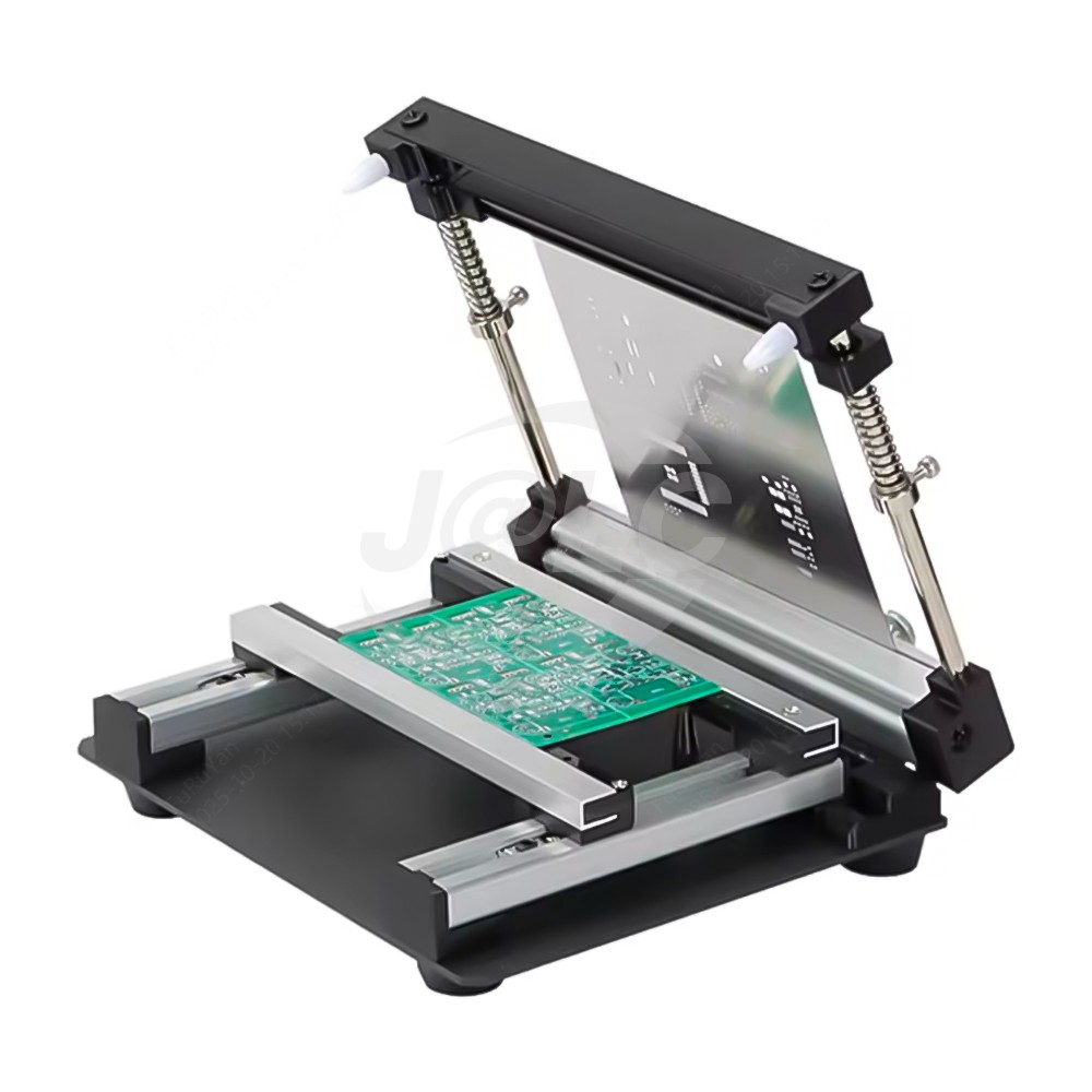
JLCMC shared catalogue illustration of the manual-printer arrangement. The image does not identify a particular size or supplied accessories; use the selected model's specifications and drawing to establish fit.
A Dimensional Screening Example
Suppose a proposed stencil has a 90 × 120 mm aperture envelope. It passes a simple axis-by-axis comparison with a listed 100 × 130 mm effective print area. That is only the first screen: the board outline, aperture position relative to the clamp, foil dimensions, and stroke access still need checking.
Now consider a 105 × 125 mm aperture envelope. It exceeds the 100 mm axis. Rotating it produces 125 × 105 mm, which still exceeds that same axis. Comparing rectangular areas would hide this incompatibility. A larger effective print envelope or a redesigned print setup would need evaluation.
Note on Clearance Margins
Neither example assigns a universal clearance margin. The necessary space depends on the printer's geometry, stencil retention, and operating method. Obtain those details instead of inventing a margin from the model name.
Board Support Matters as Much as Nominal Capacity
During printing, the squeegee applies force to the stencil and solder paste while the stencil is held in contact with the board. If the board can bow or rock, the contact condition can change during the stroke. A board that looks aligned before printing may therefore produce a different deposit pattern once force is applied.
Use a support arrangement that establishes a stable printing plane and prevents motion without damaging the PCB. Confirm that the supporting surfaces are clean and at compatible heights. Uneven or contaminated support surfaces can introduce local height differences that affect board stability and stencil contact.
For a second-side assembly, map the components already fitted to the underside. Their height and position influence where support may be placed and whether a carrier is necessary. Substrate thickness alone does not describe that three-dimensional assembly.
Industry Guidance on Gasketing
Indium's stencil-printing guidance identifies board support and stencil gasketing as important process variables. Gasketing means maintaining the intended contact between stencil and board around the apertures. The guidance supports these principles; its paste-specific operating examples should not become universal settings for a manual printer.
Separate Alignment, Contact, and Release
Alignment: Are the Apertures Over the Intended Pads?
Check widely separated features, not only one convenient component. A stencil can match at one location while rotational error causes mismatch farther away. Inspect both the central area and the extremities of the aperture field.
Record the board orientation and datum used for loading. If the operator must remember an unmarked orientation or improvise the board stop every time, a successful first print does not demonstrate repeatability.
Contact: Does the Setup Stay Seated During the Stroke?
After alignment, verify that tightening the fixture has not shifted or tilted the board. Observe the supported assembly through the intended operation without using the paste to conceal gaps or movement. Excessive pressure is not a reliable repair for an unsupported region.
A suitable printer needs enough adjustment and access to establish the required relationship between board and stencil. Its table size alone cannot establish that capability for a particular assembly.
Release: Can the Stencil Separate Without Disturbing the Print?
Plan the separation motion before making the first deposit. Depending on the printer design, the stencil or the board may move during separation. The board should remain securely supported so that the printed paste is not smeared or displaced. A board that lifts with the foil or slides as it separates has not passed setup qualification.
Release also depends on the stencil aperture geometry and solder paste. Use the stencil supplier's design guidance and the selected paste's technical data. A larger worktable does not improve an aperture that is unsuitable for the intended deposit.
How to Choose Between Two Sizes That Both Seem to Fit
Choose using the actual job list. If all planned boards fit the smaller model's print envelope and complete fixture arrangement, a larger unit may add bench-space demands without solving a real limitation. If panelization or a second-side support carrier is planned, include that configuration in the comparison now.
Treat a claimed future need as a drawing to check, not a reason to assume that the biggest model is automatically the best choice. Capacity planning becomes more useful when it refers to actual assemblies.
| Decision factor | Evidence to prepare | What would justify a different setup? |
|---|---|---|
| Aperture field | Stencil drawing with both axes | Required envelope exceeds usable print area |
| Board holding | PCB outline and loading orientation | Rails or clamps prevent stable location |
| Vertical clearance | Board thickness plus underside features | Support cannot establish the printing plane |
| Stencil retention | Foil or frame drawing | Clamp interface or aperture offset is incompatible |
| Operation | Squeegee and separation path | Stroke or lifting access is obstructed |
| Future work | Defined next-board or panel requirements | A confirmed future configuration no longer fits |
Qualify the First Print Before Running the Batch
- Begin with a clean stencil and an identified paste handled according to its supplier's instructions. Use the same board support, operator method, and loading orientation intended for the batch. Changing these after approval creates a different process.
- Inspect the paste pattern before component placement. Look for misplaced, missing, insufficient, excessive, or inconsistent deposits, bridging, smearing, and evidence that the board moved. An optical check can identify visible defects, but it does not establish deposit volume as a calibrated solder-paste inspection system would.
- If the result fails, classify the pattern before adjusting. A uniform offset suggests checking registration; defects that concentrate over an unsupported region suggest checking support and contact; deterioration over successive prints suggests reviewing cleaning and paste handling. These are diagnostic starting points, not proof of a single root cause.
- Keep a short setup record: printer model, board revision, stencil revision, paste identifier, support arrangement, orientation, inspection method, and accepted settings. Recheck the first print after changes to those items. Repeatability depends on reproducing the complete setup.
FAQ about Manual SMT Stencil Printer Sizing
Q: Can I use worktable size as the maximum print area?
No. The table can be larger than the effective print area. Compare the aperture envelope with the specified print area, then separately confirm the board, supports, and stencil fit.
Q: Does a board smaller than the print area definitely fit?
No. Its holding arrangement, stencil offset, thickness, and available stroke must also fit. The print-area comparison is an initial screening step.
Q: Can rotating the PCB solve a size problem?
Sometimes, but both dimensions and the complete setup must remain compatible. Rotating only the board while ignoring stencil orientation or support access does not establish a workable process.
Q: Can these thickness ranges be applied to a populated assembly?
They describe listed substrate thickness. Components beneath the board create additional clearance and support requirements that must be reviewed separately.
Q: Will a bigger printer improve fine-pitch printing?
Size alone does not establish fine-pitch capability. Registration, board support, stencil design, paste behavior, and the inspection process remain relevant. Qualify the actual assembly instead of deriving a capability from table dimensions.
Q: Should I specify one squeegee pressure for every board?
No universal value is established here. Follow equipment and paste guidance, account for the blade and board support, and verify the resulting deposit. Excess force can hide a setup problem without resolving it.
Conclusion: Manual SMT Stencil Printer Sizing and Setup
Choose a manual SMT stencil printer by checking four envelopes: board, apertures, stencil, and operating access. Then verify thickness, support, contact, alignment, and release using a representative print. Published dimensions help narrow the choices; the complete assembly and an accepted first print establish whether the selected setup works.
Popular Articles
Keep Learning
Threaded Standoff vs Spacer: What Is the Difference?
Key Takeaways Threaded standoffs provide both spacing and threaded attachment points, making them ideal for modular assemblies and PCBs. Spacers are unthreaded sleeves that work with through-bolts to maintain gaps in clamped assemblies, offering a simpler and more economical solution. The right choice depends on the load path, assembly sequence, material, and service environment - not just appearance or catalog naming. A threaded standoff and a spacer can look almost identical on a workbench. Both cre......
How to Choose a Threaded Standoff for PCB and Mechatronic Assemblies
Key Takeaways Select the right configuration: Choose male-female, female-female, or male-male thread configurations based on the two mating interfaces and the intended assembly sequence. Treat height as a tolerance stack: Standoff body length must satisfy clearance, electrical, thermal, and connector requirements across the full tolerance range, not just the nominal dimension. Verify thread engagement: Check male thread length against tapped-hole depth and upper screw length against usable female thre......
Threaded Standoff Guide: Types, Sizes, Materials and Applications
Key Takeaways Thread configuration first: Choose female-female, male-female or male-male based on how both sides of the assembly attach — thread config is the most practical way to classify a threaded standoff. Body length is the critical dimension: Standoff length refers to the distance between supporting faces, not total physical length. Reading the wrong length causes incorrect mounting height or screw bottoming. Material affects more than strength: Brass, stainless steel, carbon steel, aluminum an......
Ball Nose End Mill Stepover: Scallop Height and Effective Diameter
Key Takeaways Geometric Control: Stepover directly controls geometric scallop height, but it does not automatically guarantee a measured Ra value. Cusp Height Formula: For a ball radius $R$ and pass spacing $s$ on a flat surface, the ideal cusp height is $h = R - \sqrt{R^2 - \frac{s^2}{4}}$. Tool Radius Advantage: A larger ball can use wider spacing for the same ideal cusp, provided it can reach the required geometry without gouging. Effective Diameter: The active cutting diameter near the tool tip ca......
Manual SMT Stencil Printer Sizing: Print Area, PCB Support and Frame Fit
Key Takeaways Different dimensions: Worktable size, effective print area, board envelope, and stencil frame size are different dimensions. Check the full pattern: Check the whole aperture pattern in its intended orientation, including clearance for the printing stroke. Thickness is not enough: A compatible board thickness does not prove that a populated underside or a support fixture will fit. Support and contact: Stable support and close stencil-to-board contact are necessary for a repeatable printin......
Blind Rivet Guide: Types, Sizes, Uses, Installation and Removal
A blind rivet may be small, but choosing one correctly involves more than matching a rivet to the nearest drill bit. The diameter, grip range, hole size, body material, mandrel material, head style and installation tool all influence the finished joint. A rivet that looks perfectly acceptable before installation can still spin, loosen, pull through the sheet or form incorrectly on the blind side if one of these factors is overlooked. Blind rivets are widely used in sheet-metal fabrication, electrical ......