2-Bolt vs. 4-Bolt Flange Bearing Units: Selection Differences That Matter
12 min
- What Is a Flange Mounted Bearing Unit?
- 2-Bolt vs. 4-Bolt Flange Bearing Units at a Glance
- When to Use a 2-Bolt Flange Bearing Unit
- When to Use a 4-Bolt Flange Bearing Unit
- UCF vs. UCFL: Flange Bearing Designation Codes
- Flange Bearing Load Capacity: Why Bolt Count Is Not a Rating
- How to Choose a Flange Bearing Unit: A Step-by-Step Guide
- Flange Bearing Replacement Checklist: Critical Dimensions and Features
- Flange Bearing Unit Installation and Alignment Checks
- 3-Bolt and Round Flange Bearing Units: Alternative Layouts
- FAQs About 2-Bolt and 4-Bolt Flange Bearing Units
Key Takeaways
Housing geometry and space: A two-bolt flange bearing unit normally uses an oval or diamond-shaped housing, making it ideal when the mounting face is narrow or access is limited.
Bolt count vs. capacity: A four-bolt flange bearing unit normally uses a square housing suited for wider interfaces, but bolt count alone does not establish the unit's load capacity.
Machine interface priority: Choose the housing pattern based on the machine interface first. Then verify shaft size, published load and speed ratings, locking method, seals, lubrication access, and critical dimensions.
Bore match is not enough: A matching bore does not make two units interchangeable. Bolt-center spacing, shaft center location, flange outline, housing thickness, insert position, and fastener requirements must also align.
Replacement verification: For a replacement, compare the existing unit and candidate drawing line by line rather than relying solely on a familiar series prefix.
People searching for a 2 bolt flange bearing or 4 bolt flange bearing are usually comparing complete mounted bearing units, not standalone ball bearings with a small flange machined into the outer ring. In this guide, a flange bearing unit means a bearing insert installed in a housing that bolts to a machine wall, plate, or frame.
The quick answer is straightforward: choose a two-bolt unit when its oval footprint fits the mounting surface and the exact model meets the application's ratings. Choose a four-bolt unit when the machine is designed for a square four-hole pattern and the selected model meets the same technical checks. Do not use bolt count as a substitute for the manufacturer's load-rating table.
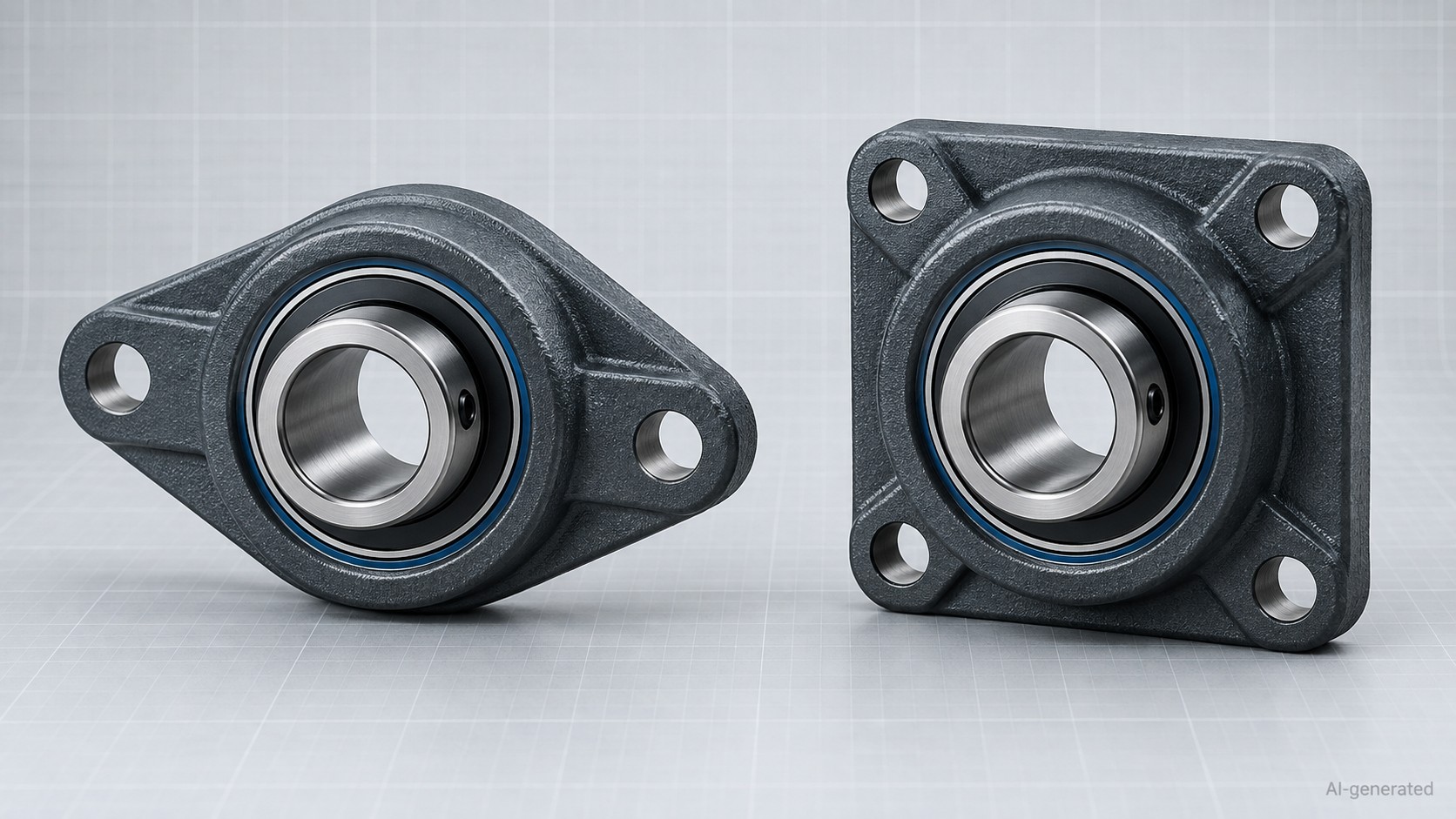
Two-bolt and four-bolt flange bearing unit configurations
What Is a Flange Mounted Bearing Unit?
A flange mounted bearing unit combines two main parts:
- A bearing insert that supports the rotating shaft.
- A flanged housing that locates the insert and attaches the assembly to the machine.
The shaft normally passes through a mounting face. That distinguishes a flange unit from a base-mounted pillow block, where the shaft axis generally runs parallel to the mounting surface. For a broader explanation of that base-mounted arrangement, see what a pillow block bearing is.
Common flange housing layouts include two-bolt oval, four-bolt square, three-bolt, and round or piloted configurations. This article focuses on the two most frequently compared layouts: the oval two-bolt unit and the square four-bolt unit.
2-Bolt vs. 4-Bolt Flange Bearing Units at a Glance
| Selection Question | 2-Bolt Flange Bearing Unit | 4-Bolt Flange Bearing Unit |
|---|---|---|
| Typical housing outline | Oval or diamond | Square |
| Typical mounting pattern | Two mounting holes, typically arranged along the housing's long axis | Four holes around the shaft center |
| Useful when | The mounting face is narrow or a compact outline is needed | The machine has a square four-hole interface or a broader attachment pattern is preferred |
| Installation access | Two mounting points, but clearance is still needed for fasteners and locking hardware | Four mounting points require access to all mounting fasteners and any locking or lubrication features |
| Replacement priority | Match bore, mounting-hole spacing, shaft-center location relative to the mounting face, and housing envelope | Match bore, horizontal and vertical bolt centers, center location, and outline |
| Capacity conclusion | Use the exact unit rating | Use the exact unit rating |
Selection Note
This table describes common geometry, not a universal performance ranking. Housing material, insert series, duty class, fasteners, mounting structure, load direction, speed, and operating environment all affect the final selection.
When to Use a 2-Bolt Flange Bearing Unit
A two-bolt unit is often considered when the machine provides a narrow mounting strip, when four bolt locations are unavailable, or when the housing must fit between nearby guards or structural members. The oval outline can reduce the amount of mounting-face area required around the shaft.
That compact outline does not remove the need for a rigid mounting surface. Both fasteners must clamp the housing evenly, and the surface must support the housing without rocking or distortion. The exact unit drawing should be checked for:
- Shaft bore and permissible shaft fit
- Center-to-center bolt spacing
- Bolt-hole size and any slot geometry
- Shaft-center location relative to the mounting face
- Overall housing width, height, and depth
- Insert projection and locking-side access
- Seal, relubrication, and end-cover clearance
A two-bolt unit is not automatically a light-duty component. Likewise, it should not be selected for a demanding application merely because the footprint fits. The published rating and application conditions decide whether a particular model is suitable.
When to Use a 4-Bolt Flange Bearing Unit
A four-bolt unit is usually considered when the machine already has a square mounting pattern or when the design provides enough face area for four attachment points. The wider pattern can help the housing attach to the structure over a broader area, but the result still depends on the housing design, fasteners, mounting plate, and applied loads.
Check more than the outside square dimension. Two square housings with the same bore may use different bolt centers, housing thicknesses, pilots, insert positions, or fastener sizes. A candidate also needs enough access for installation tools and for any set screws, locking collar, grease fitting, or cover.
Four bolts do not prove that one unit has a higher dynamic or static rating than a two-bolt unit. The published dynamic and static load ratings generally describe the bearing's load-carrying capacity. The allowable load of the complete mounted unit can also depend on the housing, mounting bolts, mounting surface, load direction, and application conditions. Check the manufacturer's specific data when these limits are critical.
UCF vs. UCFL: Flange Bearing Designation Codes
In common mounted-unit catalogs, UCF is used for a square four-bolt flange unit and UCFL for an oval two-bolt flange unit. This is helpful when scanning a product family, but the prefix is only the beginning of the selection.
The remaining series and bore characters, suffixes, locking method, seal design, material, and manufacturer-specific options still matter. Designation systems can differ. Read the nomenclature section of the exact catalog rather than decoding every product from a universal formula.
Flange Bearing Load Capacity: Why Bolt Count Is Not a Rating
It is tempting to assume that four bolts always mean more capacity. That shortcut can fail for several reasons:
- Insert limitation: The bearing insert may be the limiting component.
- Material differences: The two compared units may use different bearing series or housing materials.
- Load direction: The load direction may not act evenly through all mounting points.
- Mounting plate rigidity: The mounting plate may flex before the housing reaches its catalog limit.
- Fastener connection: Fastener grade, engagement, preload, and joint design affect the connection.
Shock and vibration can affect the applied load and service-life calculation, while speed, contamination, and temperature can affect allowable operating conditions, sealing, lubrication, and maintenance requirements.
Use the bolt pattern to choose the physical interface. Use the exact manufacturer's data to evaluate bearing load, housing limits, speed, and application suitability.
How to Choose a Flange Bearing Unit: A Step-by-Step Guide
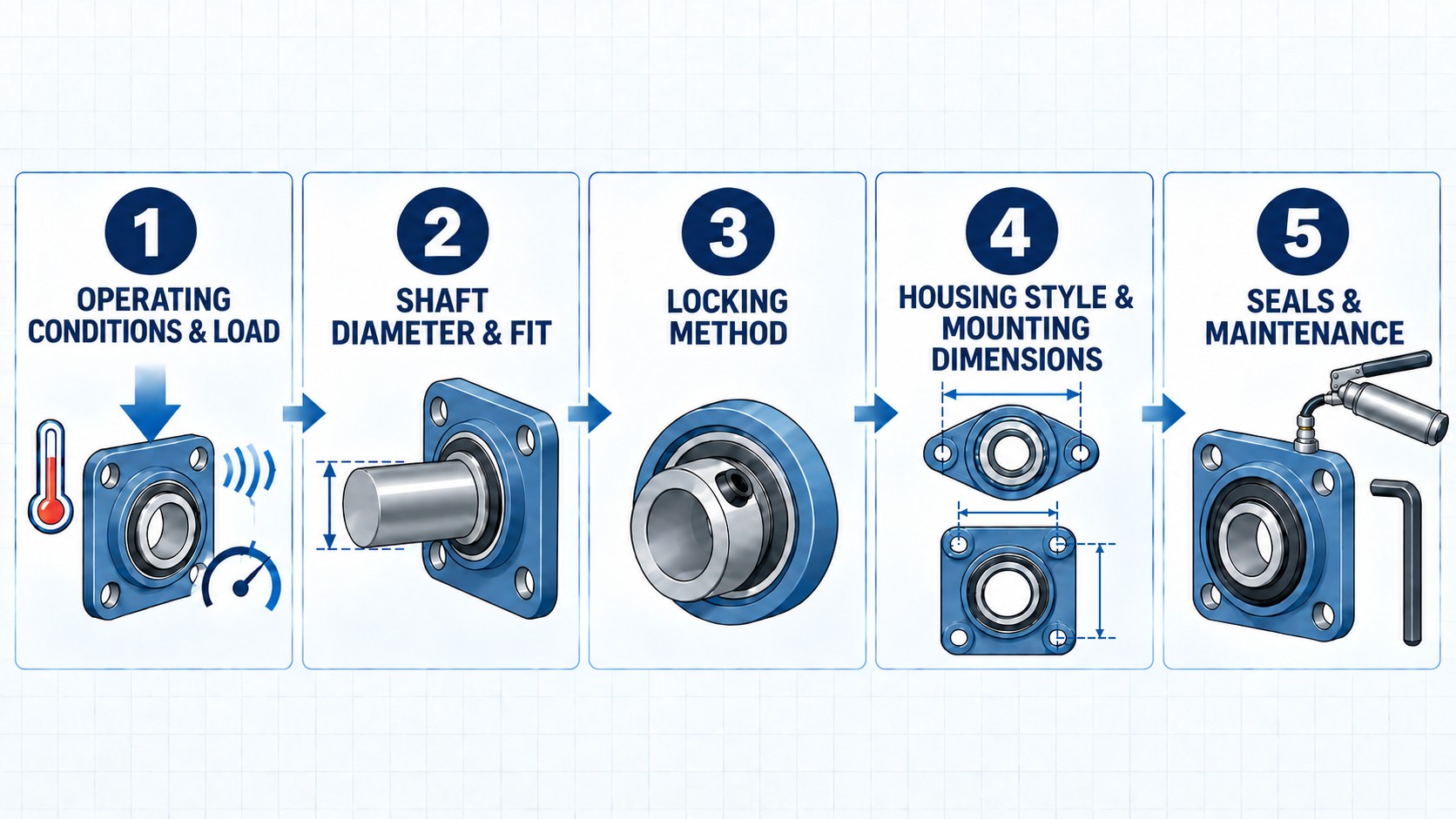
Five-step selection sequence for a flange mounted bearing unit
-
Define the Mounting Face
Confirm that the shaft passes through a wall, side plate, or frame. Record available width, height, obstructions, plate thickness, and tool access. Treat existing patterns as measured inputs.
-
Confirm the Shaft and Bore
Measure the shaft at the bearing seat and determine metric or inch sizing. Record shaft tolerance, surface condition, and wear. Never substitute a nearly equal metric or inch bore.
-
Choose the Housing Pattern
Select an oval two-bolt or square four-bolt configuration matching the mounting face. Compare bolt centers and shaft-center location before altering machine holes.
-
Verify the Exact Ratings
Use the selected product's current datasheet to check dynamic and static load ratings, speed limits, housing limits, and any permitted axial load. Do not transfer a rating from another series that happens to use the same bore.
-
Select the Shaft-Locking Method
Set screws, eccentric collars, concentric locking systems, and adapter sleeves have distinct shaft, rotation, and maintenance requirements.
-
Check Sealing and Lubrication
Dust, moisture, washdown, temperature, and chemical exposure influence seal and material selection. Make sure the grease fitting can be reached in the installed orientation and that the relubrication path belongs to the complete selected unit.
-
Review Installation and Service Access
Leave room for fasteners, torque tools, locking hardware, lubrication, guards, and future removal. A compact housing is not helpful if a set screw or grease fitting becomes inaccessible.
Flange Bearing Replacement Checklist: Critical Dimensions and Features
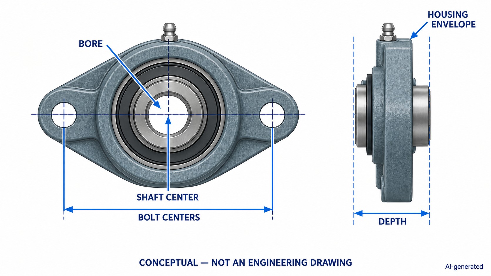
Conceptual replacement dimensions for a two-bolt flange bearing unit
For an existing flange bearing unit, record the following before ordering. For a broader measurement framework and related size references, see our guide to pillow block bearing sizes and measurement.
| Measurement or Feature | Why It Matters |
|---|---|
| Shaft diameter and unit bore | Establishes the basic shaft fit |
| Number and arrangement of mounting holes | Separates two-bolt, four-bolt, and other flange styles |
| Bolt-hole center distances | Determines whether the unit fits the existing drilled pattern |
| Bolt-hole diameter or slot size | Affects fastener fit and adjustment |
| Shaft center relative to the mounting face | Prevents alignment changes with connected equipment |
| Flange width, height, and housing depth | Checks interference with the frame, guards, and adjacent parts |
| Insert width and shaft projection | Confirms coupling, pulley, and locking-hardware clearance |
| Locking method and access side | Prevents an unserviceable installation |
| Seal and relubrication arrangement | Helps preserve the intended environmental protection and maintenance route |
| Material and coating | Must suit corrosion, washdown, and temperature requirements |
Inspection Tip
If the old housing is damaged or distorted, measure the machine interface as well as the removed part. Wear or impact can make the old component a poor dimensional reference.
Flange Bearing Unit Installation and Alignment Checks
- Isolate equipment: Stop and isolate equipment under facility-approved safety procedures.
- Clean surfaces: Thoroughly clean and inspect the shaft and mounting face.
- Check flatness: Confirm that the housing sits fully on the face without rocking.
- Align supports: Align paired supports before final fastener tightening.
- Torque in sequence: Tighten mounting fasteners and shaft-locking hardware to manufacturer torque specifications.
- Test rotation: Rotate the shaft by hand if permitted, then perform prescribed test runs.
Warning: Self-Alignment Limits
Do not correct a large shaft or structure error by forcing the housing into position. For mounted units that use a self-aligning insert, the self-aligning feature is intended to accommodate only the amount of initial misalignment specified by the manufacturer. It is not a substitute for correcting a bent shaft, distorted plate, or offset bearing centers.
3-Bolt and Round Flange Bearing Units: Alternative Layouts
Two- and four-bolt units are not the only options. Three-bolt flanges, round flanges, and piloted flange units solve different packaging or location requirements. A pilot helps locate the housing relative to a machined bore opening, while a three-bolt pattern fits interfaces that cannot accommodate a square flange.
Treat these as different machine interfaces, not automatic upgrades or downgrades. Match the geometry first, then verify ratings and operational needs.
FAQs About 2-Bolt and 4-Bolt Flange Bearing Units
Q: Is a 4-bolt flange bearing stronger than a 2-bolt flange bearing?
Not necessarily. Four mounting points create a different attachment pattern, but the usable load depends on the complete unit, housing, insert, fasteners, mounting structure, load direction, and operating conditions. Always compare published ratings for the exact models.
Q: Can I replace a 2-bolt flange bearing unit with a 4-bolt unit?
Only after the machine interface and engineering requirements are reviewed. The bolt pattern, available face area, shaft center, housing depth, ratings, locking method, and service access may all change. A matching bore alone is not enough.
Q: What is the difference between UCF and UCFL?
In common mounted-unit designation systems, UCF identifies a square four-bolt flange unit and UCFL identifies an oval two-bolt flange unit. Exact suffixes and series meanings remain manufacturer-specific, so check the current nomenclature and drawing for the selected product.
Q: Can the same insert bearing be used in two-bolt and four-bolt housings?
Some product families use a common insert across multiple housing styles, but this must be confirmed from the manufacturer's parts data. Housing seat geometry, lubrication paths, anti-rotation features, and insert variants can differ.
Q: Which dimensions matter most for a replacement?
Start with shaft diameter, bolt-hole pattern and spacing, shaft-center location, overall housing envelope, insert position, locking method, and lubrication access. Then verify ratings, materials, and environmental suitability.
Final Selection Summary: Matching the Flange Bearing Unit to Your Machine
The practical difference between a two-bolt and four-bolt flange bearing unit begins with the machine interface. A two-bolt oval housing can fit a narrow mounting area; a four-bolt square housing uses a broader four-point pattern. Neither description replaces the exact product rating.
Define the mounting face, measure the shaft and hole pattern, and then compare the current drawings and ratings for the candidate unit. To review available housing shapes, materials, bore options, and series, browse JLCMC's flange and pillow block bearing units. Confirm every critical parameter against the selected product page or drawing before ordering or modifying the machine.
References
- SKF, Insert Bearing Units — UC Range. Designation system (F = square four-bolt flange, FL = oval two-bolt flange).
- Timken, U Series Ball Bearing Housed Unit Catalog. Separate two-bolt and four-bolt unit families; model-specific dimensions and ratings.
- Timken, Fafnir Mounted Ball Bearing Catalog 11437. Flange unit mounting principles and multiple bolt-pattern configurations.
- JLCMC, Pillow Block Bearing Units. Housing shape, material, bore, and series filters.
- JLCMC, What Are Pillow Block Bearings? Types and selection guide.
- JLCMC, Pillow Block Bearing Sizes & Measurement Guide. Dimensions, measurement, and replacement procedures.
Keep Learning
Drill Bit Size Chart: Number, Letter, Fractional & Metric
Key Takeaways A drill bit size chart has to cover four systems — fractional (inches), number (#1–#80), letter (A–Z), and metric (mm) — because the same physical diameter can carry three different callouts. Number sizes provide intermediate diameters between standard fractional-inch drill sizes, allowing finer selection where 1/64-inch increments are too coarse — which is why a 1/4-20 tap takes a #7 drill (0.201 inch). Convert decimal inches to millimeters by multiplying by 25.4; the charts below give ......
2-Bolt vs. 4-Bolt Flange Bearing Units: Selection Differences That Matter
Key Takeaways Housing geometry and space: A two-bolt flange bearing unit normally uses an oval or diamond-shaped housing, making it ideal when the mounting face is narrow or access is limited. Bolt count vs. capacity: A four-bolt flange bearing unit normally uses a square housing suited for wider interfaces, but bolt count alone does not establish the unit's load capacity. Machine interface priority: Choose the housing pattern based on the machine interface first. Then verify shaft size, published loa......
NPT Thread Guide: Charts, Tap Drill Sizes, and Fitting Identification
Key Takeaways NPT (National Pipe Taper) is a U.S. standard tapered pipe thread defined by ASME B1.20.1: a 60° thread angle and a 1:16 taper on diameter, sealing through thread interference plus sealant. NPT tap drill sizes do not follow the diameter-minus-pitch formula used for straight machine threads — ASME B1.20.1 Appendix B provides guidance, and the tap manufacturer's data decides. The everyday sizes: 1/8 NPT (27 TPI, 0.405 inch major diameter), 1/4 NPT (18 TPI, 0.540 inch), 1/2 NPT (14 TPI, 0.84......
Tap Drill Chart: UNC, UNF, Metric & NPT Drill Sizes
Key Takeaways A tap drill creates the hole a tap cuts internal threads into; the drill diameter controls how much full thread the finished hole has. For Unified inch threads, drill size = major diameter − 1/TPI (rounded to the nearest standard drill) is a commonly used starting point for approximately 75 percent thread engagement; the actual percentage depends on thread geometry and the specified hole tolerance. For metric threads, the quick formula is drill = thread diameter − pitch in millimeters, r......
Comparing Brushless Motors and Stepper Motors: Principles, Structures & Applications
We have many machines around us that have electric motors to operate, including simple tools and complex robots. Brushless DC (BLDC) motors and stepper motors are two popular options for high precision and performance. They are both electrically commutated motors and have no physical brushes, but operate in different ways and are appropriate for different applications. Key Takeaways The advantages of BLDC motors are high-speed, smooth, continuous operation, and high efficiency. Stepper motors can be u......
DC Motor vs. Stepper Motor: What Are They and How Do They Differ?
To clearly distinguish between DC motors and stepper motors, this article uses brushed DC motors as the primary reference for comparison. A brushed DC motor is typically well suited for continuous rotation, high-speed operation, and variable-speed control, while a stepper motor is commonly used for low-speed positioning, indexing, and holding torque at standstill. When combined with an encoder and an appropriate controller, a brushed DC motor can also be used for closed-loop positioning. The right cho......