How to Choose Blind Rivet Size, Diameter and Grip Range
19 min
- 1. What Does Blind Rivet Size Mean?
- 2. Blind Rivet Diameter: More Than a Hole-Filling Dimension
- 3. What Is Blind Rivet Grip Range?
- 4. What Happens When the Grip Range Is Wrong?
- 5. Blind Rivet Length vs Grip Range
- 6. How to Choose the Correct Blind Rivet Hole Size
- 7. Head Diameter, Edge Distance and Rivet Spacing
- 8. Tensile and Shear Strength in Blind Rivet Selection
- 9. Practical Blind Rivet Size Selection Examples
- 10. Common Blind Rivet Sizing Mistakes
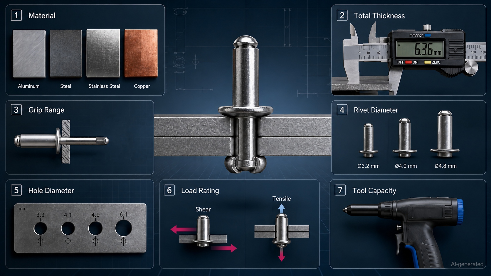
- 11. Blind Rivet Size Selection Checklist
- Frequently Asked Questions
- Conclusion
Choosing a blind rivet size is not quite as simple as finding one that passes through the hole.
The rivet must fit the prepared hole, cover the full thickness of the joint, form correctly on the blind side and provide enough mechanical strength for the application. A rivet that is too short may not form a secure closing head. One that is unnecessarily long may clamp poorly, leave excessive material behind the joint or behave unpredictably during installation.
The most important selection parameters are:
· Rivet diameter
· Body length
· Grip range
· Recommended hole diameter
· Joint thickness
· Head size
· Tensile and shear load ratings
· Blind-side clearance
This guide explains how these dimensions work together and how to choose the correct blind rivet for sheet metal, electrical enclosures, machine covers and other mechatronic assemblies.
For a broader introduction to blind rivet types, materials, applications and installation, refer to the complete blind rivet guide.
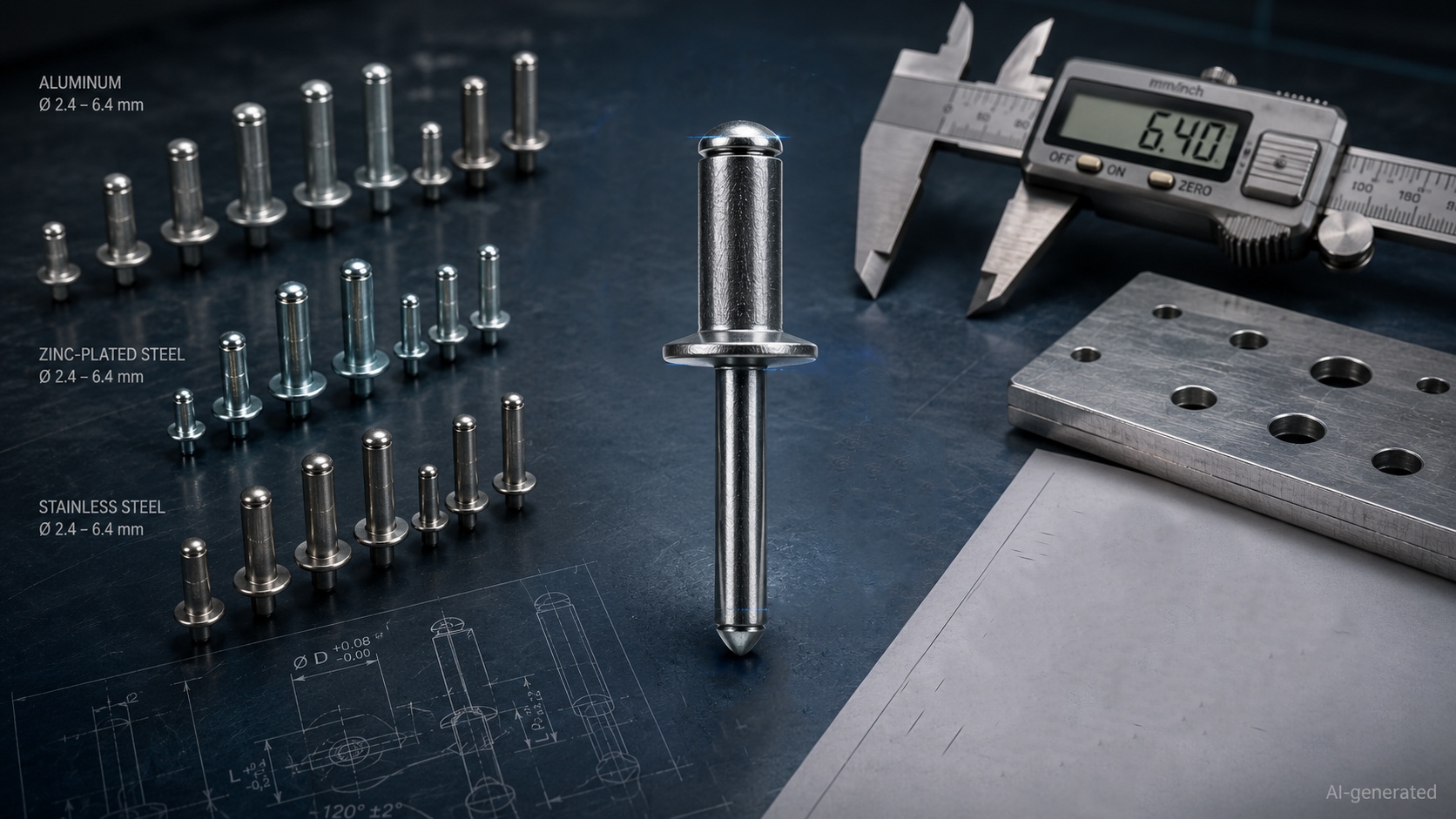
1. What Does Blind Rivet Size Mean?
A blind rivet is commonly identified using two nominal dimensions:
Rivet diameter × rivet body length
For example, a rivet described as 4 × 10 mm normally has:
· A nominal body diameter of 4 mm
· A nominal body length of 10 mm
The length does not include the exposed portion of the mandrel. It is generally measured from beneath the factory head to the end of the rivet body.
However, these two numbers do not tell the whole story.
A complete blind rivet specification may also include:
· Grip range
· Recommended hole diameter
· Head diameter
· Head height
· Mandrel diameter
· Blind-side clearance
· Minimum tensile load
· Minimum shear load
· Body material
· Mandrel material
Two blind rivets with the same nominal diameter and body length may have different grip ranges or load ratings if their body geometry, materials or mandrel designs are different.
This is why blind rivet selection should be based on the complete product data rather than the nominal size alone.
JLCMC blind rivet specifications, for example, identify parameters such as hole diameter, riveting range, minimum tensile load and minimum shear load alongside the nominal diameter and length.
2. Blind Rivet Diameter: More Than a Hole-Filling Dimension
The nominal blind rivet diameter is the outside diameter of the rivet body before installation.
Common metric blind rivet diameters include sizes such as:
· 2.4 mm
· 3.0 mm
· 3.2 mm
· 4.0 mm
· 4.8 mm
· 5.0 mm
· 6.0 mm
· 6.4 mm
The available range depends on the rivet series, material and manufacturer.
How Diameter Affects the Joint
Rivet diameter influences several aspects of the connection:
· Required hole diameter
· Tensile load capacity
· Shear load capacity
· Bearing pressure on the sheet
· Minimum space around the hole
· Required installation force
· Tool and nosepiece selection
Increasing the diameter can improve the load capacity of a suitable rivet, but it also removes more material from the workpiece.
That trade-off matters in narrow brackets, thin flanges and closely spaced sheet-metal joints. A larger rivet is not automatically a better rivet if the surrounding material cannot support the larger hole.
Choose Diameter from Load Data, Not Guesswork
It is tempting to choose a diameter by copying a nearby screw or selecting the largest rivet that fits the available space.
A better process is to compare:
1.The expected load on the joint
2.The rivet’s published tensile and shear ratings
3.The strength and thickness of the joined materials
4.The number and spacing of rivets
5.The available edge distance
6.The installation tool capacity
Blind rivets of the same diameter do not necessarily have the same strength. An aluminum open-end rivet, a stainless steel rivet and a structural retained-mandrel rivet may behave very differently.
Published load data should therefore be treated as part of the size—not as an optional footnote hiding at the bottom of the specification sheet.
3. What Is Blind Rivet Grip Range?
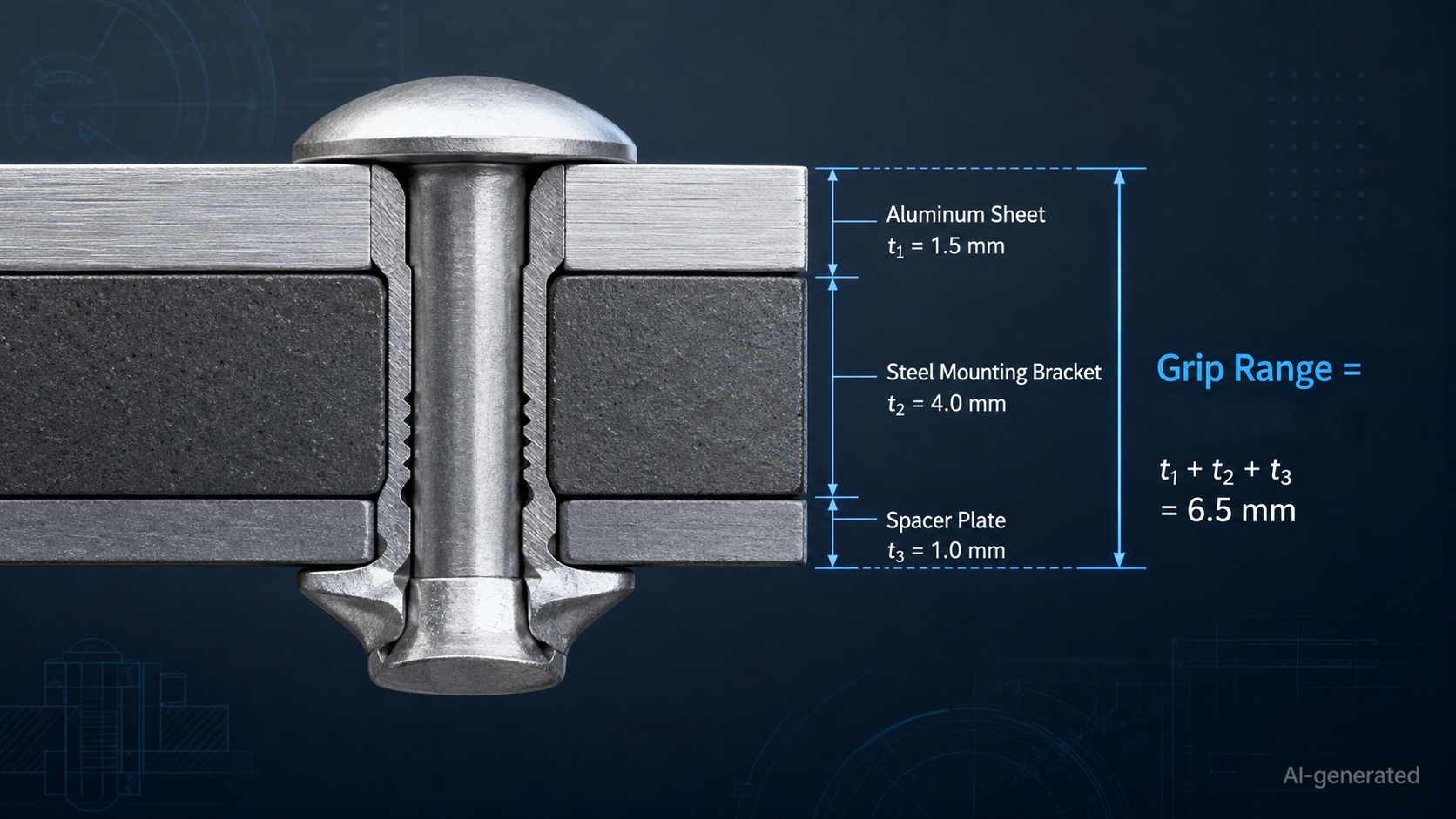
Blind rivet grip range is the total thickness of material that the rivet is designed to clamp correctly.
Some product specifications use the term riveting range instead. In normal selection work, both terms describe the acceptable combined thickness of the material stack.
For example, a rivet marked with a grip range of:
2.0–4.0 mm
is intended to join material layers whose total thickness falls between 2.0 and 4.0 mm.
Grip range does not refer to:
· The thickness of only the front sheet
· The thickness of only the rear sheet
· The diameter of the rivet
· The full length of the rivet body
· The amount of mandrel visible before installation
It refers to the entire clamped stack.
GESIPA defines grip range as the total combined material thickness that a blind rivet can securely join.
How to Calculate Total Grip Thickness
Add together every layer that will be clamped between the factory head and the blind-side closing head.
For example:
| Joint layer | Thickness |
| Outer sheet | 1.2 mm |
| Mounting bracket | 2.0 mm |
| Spacer plate | 0.8 mm |
| Total grip thickness | 4.0 mm |
The selected blind rivet must include 4.0 mm within its published grip range.
A rivet with a grip range of 2.0–4.0 mm may be suitable.
A rivet with a range of 0.5–3.0 mm is too short for the joint, even if its body can physically be pushed through the hole.
Include Every Layer That Affects the Stack
Depending on the assembly, the total thickness may include:
· Multiple sheet-metal panels
· Brackets
· Washers
· Reinforcement plates
· Gaskets
· Spacers
· Surface layers
· Folded sheet sections
Paint and thin plating are usually not treated as major structural layers, but thick coatings, soft gaskets or compressible materials may affect the installed joint. Where compression or relaxation is possible, the assembly should be tested rather than sized from nominal dimensions alone.
4. What Happens When the Grip Range Is Wrong?
Grip range has a direct effect on how the blind-side closing head forms.
A rivet may enter the hole perfectly and still produce a poor joint if the material stack falls outside the specified range.
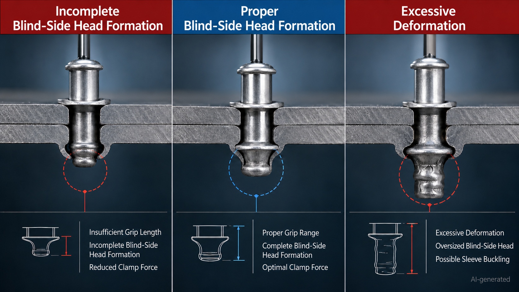
When the Rivet Is Too Short
If the joint thickness exceeds the maximum grip range, there may not be enough deformable rivet body behind the material.
Possible results include:
· Incomplete blind-side head formation
· Low clamping force
· Premature mandrel breakage
· A loose joint
· Reduced tensile performance
· Poor resistance to vibration
· Rivet pull-out
In severe cases, the rivet may appear to have set because the mandrel snapped, while the joint remains loose. The sound effect worked; the fastening did not.
When the Rivet Is Too Long
If the joint thickness is below the minimum grip range, too much rivet body may remain available for deformation.
Possible results include:
· Excessive blind-side projection
· Irregular closing-head formation
· Reduced clamp consistency
· Rivet body buckling
· Incomplete hole filling
· A loose or flexible joint
· Interference with internal components
A longer rivet is not a universal safety margin. Blind rivets are designed to form within a defined thickness range.
Choosing Near a Grip-Range Boundary
When the measured joint thickness is very close to the minimum or maximum listed value, consider:
· Material thickness tolerance
· Coating thickness
· Part-to-part variation
· Burrs
· Surface flatness
· Compression of soft layers
· Production measurement accuracy
For repeated production, measure several actual assemblies rather than relying only on nominal CAD dimensions.
5. Blind Rivet Length vs Grip Range
Body length and grip range are related, but they are not the same parameter.
Body Length
Blind rivet body length is generally measured from beneath the factory head to the end of the tubular body.
Grip Range
Grip range describes the material thickness that the rivet can clamp correctly after installation.
The body must be longer than the material stack because part of the rivet must extend beyond the rear surface and deform into the closing head.
A Useful Estimation Formula
For some standard blind rivets, a practical preliminary estimate is:
Rivet body length ≈ total grip thickness + rivet diameter
For example, if two 3 mm sheets are joined with a 4 mm blind rivet:
· Total grip thickness: 3 mm + 3 mm = 6 mm
· Rivet diameter: 4 mm
· Estimated body length: 6 mm + 4 mm = 10 mm
GESIPA presents this calculation as a practical method for estimating the appropriate length of a standard blind rivet.
However, this is an estimation method—not a replacement for the manufacturer’s grip-range table.
Different blind rivet designs form differently. Multi-grip, peel, bulb, structural and closed-end rivets may not follow the same simple relationship.
The final selection should always be confirmed against the exact product specification.
6. How to Choose the Correct Blind Rivet Hole Size
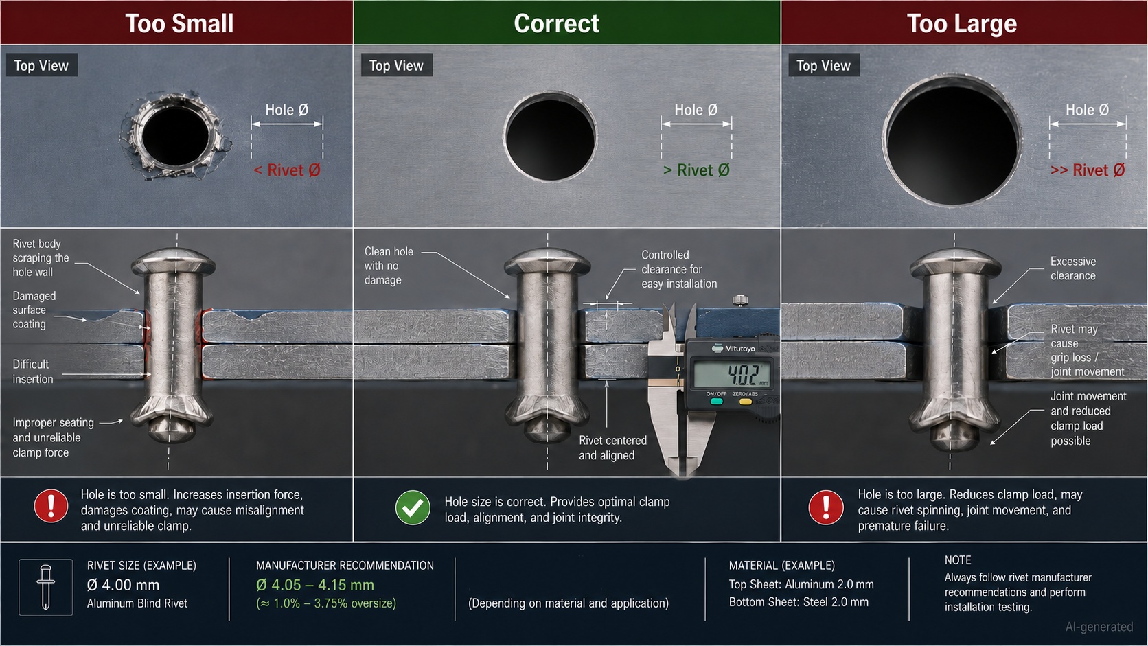
The prepared hole must be large enough for the rivet body to enter without damage, but small enough to support correct setting and hole filling.
Why the Hole Is Slightly Larger Than the Rivet
A blind rivet usually requires a hole slightly larger than its nominal body diameter.
For a standard rivet, the difference may be small. GESIPA gives an illustrative recommendation of a hole approximately 0.1 mm larger than the rivet diameter, such as a 4.9 mm hole for a 4.8 mm rivet. Actual requirements must still be taken from the selected rivet’s product data.
Published JLCMC specifications similarly list a recommended hole-diameter range for each blind rivet diameter rather than assuming that the hole and rivet are exactly the same size.
Problems Caused by an Undersized Hole
A hole that is too small may cause:
· Difficulty inserting the rivet
· Damage to coatings or plating
· Scraping of the rivet body
· Rivet misalignment
· Distortion of thin sheet
· Installation delays
Forcing the rivet into an undersized hole is not precision assembly. It is an early warning that the hole process needs attention.
Problems Caused by an Oversized Hole
A hole that is too large may cause:
· Rivet spinning
· Poor centering
· Reduced hole filling
· Uneven load distribution
· Joint movement
· Low clamp consistency
· Visible gaps around the head
· Reduced fatigue performance
Stanley Engineered Fastening notes that hole size should match the rivet specification closely and identifies grip range as the total material thickness the rivet is designed to clamp.
Hole Shape and Alignment Matter Too
Correct diameter alone is not enough.
Check that the hole is:
· Round
· Perpendicular to the surface
· Free from heavy burrs
· Aligned through all layers
· Free from cracks
· Clear of loose chips
· Not distorted by punching or drilling
Misaligned holes can force the rivet body sideways and interfere with blind-side formation.
Where several layers are drilled separately, use appropriate locating or clamping methods to prevent the parts from shifting during hole preparation.
7. Head Diameter, Edge Distance and Rivet Spacing
Blind rivet selection also depends on the amount of material around the hole.
Head Diameter
The factory head must distribute load across the accessible surface without pulling through or crushing the material.
A standard dome head is suitable for many metal-sheet applications.
A large-flange head may be more appropriate for:
· Thin sheet
· Plastic
· Composite panels
· Soft material
· Slightly enlarged holes
· Joints requiring a wider bearing area
Large-flange blind rivets provide a broader contact surface, helping reduce tearing in thin, soft or brittle materials, although they do not replace accurate hole preparation.
Edge Distance
Edge distance is the distance from the center of the rivet hole to the nearest free edge of the material.
If the hole is too close to an edge, the remaining material may:
· Tear
· Crack
· Deform
· Bend outward
· Fail under shear or peel load
There is no single edge-distance value suitable for every blind rivet and material combination. The correct distance depends on rivet diameter, workpiece material, sheet thickness, load direction and joint design.
Use the applicable design requirements and validate heavily loaded joints.
Rivet Spacing
Spacing affects how load is shared between several rivets.
Rivets placed too close together may weaken the material between holes. Rivets placed too far apart may allow sheets to separate, flex, vibrate or leak between fastening points.
When designing a rivet pattern, consider:
· Applied load
· Panel stiffness
· Material thickness
· Joint overlap
· Vibration
· Sealing requirements
· Manufacturing tolerance
Do not simply place as many rivets as the CAD pattern tool can fit. More holes do not automatically create a stronger panel.
8. Tensile and Shear Strength in Blind Rivet Selection
Once diameter and grip range are understood, check whether the rivet can carry the expected load.
Shear Load
Shear load acts across the rivet body and tries to slide the joined sheets relative to each other.
Examples include:
· A bracket supporting a vertical component
· A cover resisting lateral vibration
· Two overlapping panels carrying an in-plane load
Tensile Load
Tensile load acts along the rivet axis and tries to pull the materials apart.
Examples include:
· A panel being pulled away from a frame
· Internal pressure acting on a cover
· A bracket loaded perpendicular to the mounting surface
Real Joints Often See Combined Loads
A machine cover may experience:
· Shear from its own weight
· Tension from vibration
· Peel at the sheet edge
· Repeated fatigue loading
· Occasional impact during maintenance
For that reason, blind rivet selection should not be based on only one idealized load direction.
JLCMC blind rivet product data includes minimum tensile and minimum shear load values, allowing engineers and purchasing teams to compare mechanical performance alongside diameter, hole size and riveting range.
Do Not Compare Materials by Diameter Alone
A 4 mm stainless steel blind rivet may have a different rating from a 4 mm aluminum blind rivet.
Performance can also vary with:
· Open-end or closed-end construction
· Mandrel retention
· Structural or non-structural design
· Body alloy
· Mandrel alloy
· Head geometry
· Manufacturer tolerances
For a detailed comparison of corrosion resistance, weight, strength and installation force, refer to the supporting guide on aluminum vs steel vs stainless steel blind rivets.
9. Practical Blind Rivet Size Selection Examples
The following examples illustrate the selection process. They are not substitutes for product-specific technical data.
Example 1: Electrical Enclosure Panel
An aluminum enclosure panel is attached to a steel internal bracket.
· Aluminum panel: 1.5 mm
· Steel bracket: 2.0 mm
· Total grip thickness: 3.5 mm
Selection process:
1.Find a blind rivet with a grip range that includes 3.5 mm.
2.Choose a diameter based on the expected load and available edge distance.
3.Verify the recommended hole diameter.
4.Check material compatibility between the rivet, aluminum panel and steel bracket.
5.Confirm that the tool can set the selected body and mandrel materials.
6.Review tensile and shear ratings.
A rivet marked for a 3–5 mm grip range may be appropriate from a thickness standpoint. The final choice still depends on the specific product data and joint environment.
Example 2: Machine Guard with Three Layers
A machine guard is assembled from:
· Outer sheet: 1.0 mm
· Reinforcement strip: 1.5 mm
· Mounting flange: 2.0 mm
Total grip thickness:
1.0 + 1.5 + 2.0 = 4.5 mm
A rivet with a maximum grip of 4.0 mm is too short.
A rivet covering 4.0–6.0 mm may fit the joint, provided that the selected series defines 4.5 mm within its acceptable range.
The designer should also check whether the reinforcement strip creates any local gap. A nominal 4.5 mm stack that is not tightly assembled may behave like a thicker joint during setting.
Example 3: Plastic Cover on a Metal Frame
A plastic cover is attached to a steel frame.
· Plastic cover: 2.5 mm
· Steel frame: 1.5 mm
· Total grip thickness: 4.0 mm
In addition to choosing a grip range that includes 4.0 mm, consider:
· A larger factory head to reduce surface pressure
· A peel or load-spreading blind-side design
· Lower setting force
· Plastic creep and temperature
· Hole clearance
· Risk of cracking
The grip range may be correct while the rivet type is still wrong. Size and design must be considered together.
Example 4: Variable Sheet Thickness in Production
A product family uses joint thicknesses of:
· 2.8 mm
· 3.6 mm
· 4.4 mm
A multi-grip blind rivet may cover all three assemblies and simplify inventory.
Some multi-grip products can replace several standard grip lengths and provide controlled hole filling, but their published range and load ratings must still be checked.
The inventory benefit is useful only when the rivet performs correctly in every joint variation.
10. Common Blind Rivet Sizing Mistakes
Choosing by Body Length Alone
A rivet may look long enough while its specified grip range is unsuitable.
Always select from the published grip range.
Measuring Only One Sheet
Grip range applies to the total joint thickness.
Add every clamped layer.
Assuming the Hole Equals the Rivet Diameter
The recommended hole is normally slightly larger than the nominal body diameter.
Use the product specification.
Using an Oversized Hole to Fix Misalignment
An enlarged hole may make assembly easier but reduce joint consistency and allow spinning or movement.
Correct the hole-position or fixture problem instead.
Selecting the Largest Diameter Available
A larger hole may weaken a narrow flange or leave insufficient edge distance.
Choose diameter from load and joint-design requirements.
Ignoring Material Tolerance
Nominal sheet thickness is not always the same as actual stack thickness.
Measure representative production parts.
Treating a Longer Rivet as Safer
Excess length can produce poor deformation and low clamp consistency.
Stay within the stated grip range.
Ignoring Tool Capacity
Larger diameters and stronger materials require more pulling force.
Confirm that the tool and nosepiece are suitable before releasing the rivet to production.
Forgetting Blind-Side Clearance
The rivet body must have enough space behind the joint to form its closing head.
Check for nearby:
· Wiring
· Circuit boards
· Sensors
· Insulation
· Internal ribs
· Folded sheet walls
· Moving parts
A one-sided fastener still needs room on its blind side. It simply does not need a wrench there.
11. Blind Rivet Size Selection Checklist
Before ordering or installing a blind rivet, confirm the following:
| Selection item | What to check |
| Base materials | Steel, stainless steel, aluminum, plastic or mixed materials |
| Total joint thickness | Sum of all clamped layers |
| Grip range | Must include the measured total thickness |
| Rivet diameter | Suitable for load, space and surrounding material |
| Hole diameter | Matches the selected product specification |
| Hole condition | Round, aligned, clean and deburred |
| Body length | Consistent with the specified grip range |
| Head style | Dome, large flange or countersunk |
| Tensile rating | Suitable for axial separation loads |
| Shear rating | Suitable for sliding loads |
| Edge distance | Enough material remains around the hole |
| Rivet spacing | Supports the panel and distributes load |
| Blind-side clearance | Enough space for closing-head formation |
| Rivet material | Compatible with strength and corrosion requirements |
| Tool capacity | Correct nosepiece, diameter range and pulling force |
For JLCMC products, reviewing the technical drawing and specification table before ordering helps align the blind rivet diameter, hole diameter, riveting range and load performance with the actual assembly.
Frequently Asked Questions
What Is the Most Important Blind Rivet Size?
There is no single most important dimension. Diameter, grip range and recommended hole diameter must work together.
In most selection errors, however, incorrect grip range is the reason a rivet that “looks right” forms a poor joint.
How Do I Measure Blind Rivet Grip Range?
Measure the total thickness of every material layer the rivet will clamp.
Do not include the projecting mandrel or the free space behind the joint.
Should Blind Rivet Length Equal Material Thickness?
No. The body must extend beyond the material so it can deform and form a closing head.
Select from the manufacturer’s grip-range table rather than matching body length directly to sheet thickness.
Can I Use a Blind Rivet That Is Slightly Too Long?
A rivet should not be selected outside its published grip range. Too much free body length can cause irregular deformation, poor hole filling or reduced clamping.
What Drill Size Should I Use for a Blind Rivet?
Use the recommended hole diameter in the product specification.
The hole is usually slightly larger than the rivet body, but there is no universal drill size for every product.
Does a Larger Blind Rivet Hold More Weight?
A larger diameter may provide greater capacity within a comparable product family, but joint strength also depends on material, rivet design, grip condition, hole quality, load direction and the strength of the workpiece.
What Is the Difference Between Grip Range and Riveting Range?
They are commonly used to describe the same selection parameter: the combined thickness of material that the blind rivet is designed to clamp.
Can One Blind Rivet Size Cover Several Material Thicknesses?
Yes, when all thicknesses fall within the published grip range.
Multi-grip blind rivets are specifically designed to accommodate a wider thickness range and may reduce the number of rivet lengths needed in production.
Conclusion
Choosing the correct blind rivet size starts with the joint—not with the rivet tray.
Measure the full material stack, select a grip range that includes that thickness, choose a diameter supported by the required tensile and shear performance, and prepare the hole according to the exact product specification.
Then verify the details that are easy to overlook:
· Head diameter
· Edge distance
· Rivet spacing
· Material compatibility
· Blind-side clearance
· Installation-tool capacity
A blind rivet that is too short may not form a complete closing head. One that is too long may clamp inconsistently. An oversized hole may allow the rivet to spin, while an unnecessarily large diameter may weaken the surrounding sheet.
The right blind rivet should fit the hole cleanly, remain within its specified grip range, form consistently and meet the mechanical demands of the assembly.
Engineers and purchasing teams can use the specifications available through the JLCMC Rivets category to compare blind rivet diameter, hole requirements, riveting range, body material and minimum tensile and shear loads before placing the fastener into a sheet-metal or mechatronic design.
Popular Articles
Keep Learning
Threaded Standoff Guide: Types, Sizes, Materials and Applications
Key Takeaways Thread configuration first: Choose female-female, male-female or male-male based on how both sides of the assembly attach — thread config is the most practical way to classify a threaded standoff. Body length is the critical dimension: Standoff length refers to the distance between supporting faces, not total physical length. Reading the wrong length causes incorrect mounting height or screw bottoming. Material affects more than strength: Brass, stainless steel, carbon steel, aluminum an......
How to Choose a Threaded Standoff for PCB and Mechatronic Assemblies
Key Takeaways Select the right configuration: Choose male-female, female-female, or male-male thread configurations based on the two mating interfaces and the intended assembly sequence. Treat height as a tolerance stack: Standoff body length must satisfy clearance, electrical, thermal, and connector requirements across the full tolerance range, not just the nominal dimension. Verify thread engagement: Check male thread length against tapped-hole depth and upper screw length against usable female thre......
Drawer Slide Selection Guide for Equipment Trays: Sizing, Load Calculation & Locking
Key Takeaways Gross Load First: Calculate the moving assembly's gross load, including the tray, brackets, equipment and attached accessories. Travel, Not Rail Length: Specify the actual travel needed for service access; nominal rail length alone does not establish that travel. Know Your Lock: Distinguish a positive lock, a detent, a soft-close feature and a disconnect mechanism. Three Independent Checks: Treat slide capacity, mounting-bracket strength and cabinet tipping resistance as separate checks.......
Threaded Standoff vs Spacer: What Is the Difference?
Key Takeaways Threaded standoffs provide both spacing and threaded attachment points, making them ideal for modular assemblies and PCBs. Spacers are unthreaded sleeves that work with through-bolts to maintain gaps in clamped assemblies, offering a simpler and more economical solution. The right choice depends on the load path, assembly sequence, material, and service environment - not just appearance or catalog naming. A threaded standoff and a spacer can look almost identical on a workbench. Both cre......
Ball Nose End Mill Stepover: Scallop Height and Effective Diameter
Key Takeaways Geometric Control: Stepover directly controls geometric scallop height, but it does not automatically guarantee a measured Ra value. Cusp Height Formula: For a ball radius $R$ and pass spacing $s$ on a flat surface, the ideal cusp height is $h = R - \sqrt{R^2 - \frac{s^2}{4}}$. Tool Radius Advantage: A larger ball can use wider spacing for the same ideal cusp, provided it can reach the required geometry without gouging. Effective Diameter: The active cutting diameter near the tool tip ca......
Manual SMT Stencil Printer Sizing: Print Area, PCB Support and Frame Fit
Key Takeaways Different dimensions: Worktable size, effective print area, board envelope, and stencil frame size are different dimensions. Check the full pattern: Check the whole aperture pattern in its intended orientation, including clearance for the printing stroke. Thickness is not enough: A compatible board thickness does not prove that a populated underside or a support fixture will fit. Support and contact: Stable support and close stencil-to-board contact are necessary for a repeatable printin......