Main Types of Servo Motors: AC, DC, and Everything in Between
11 min
- 1. Introduction
- 2. What are the different types of servo motors?
- 3. Other Classification Methods: Classification by Mechanical Construction
- 4. Other Classification Methods: Classification by Performance Specifications
- 5. Comprehensive Servo Motor Comparison Matrix
- 6. Selection Guide: How to Choose the Right Servo Motor
- 7. Frequently Asked Questions (FAQ)
- 8. Conclusion
1. Introduction
By leveraging closed-loop feedback to precisely control position, velocity, and torque, servo motors serve as the backbone of modern automation. Yet, application success hinges on matching the right architecture to your load requirements—a task made challenging by the sheer variety of servo motor types available today.
In this article, we map motor technology to application requirements through a practical taxonomy covering electrical topology, mechanical construction, performance specifications, and selection logic—helping engineers make faster, more accurate decisions.
2. What are the different types of servo motors?
Different types of servo motors are split primarily by power supply—DC versus AC—then by commutation method and rotor construction. This classification determines driving electronics, maintenance schedules, and thermal behavior.
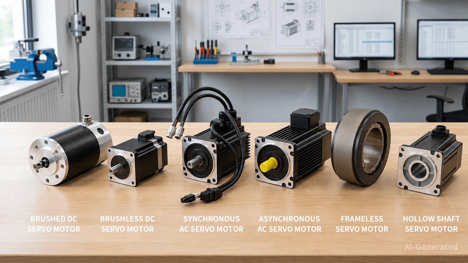
Fig. 1: The image lists 6 common types of servo motors: DC (brushed and brushless), AC (synchronous and asynchronous), and specialized types, such as frameless and hollow-shaft servo motors.
2.1 DC Servo Motors
DC servo motors operate from low-voltage supplies or battery buses. They are divided into brushed and brushless architectures, with the latter dominating new designs due to longevity advantages.
2.1.1 Brushed DC Servos
Brushed units remain relevant where periodic maintenance is acceptable and drive simplicity outweighs longevity.
Working Principle: Brushed DC servos use mechanical commutation via carbon brushes on a copper commutator. Current through armature windings generates torque proportional to current. Position feedback closes the loop through encoders or potentiometers. Brush wear can lead to contamination and limit the overall service life, with the extent of wear depending heavily on current density, operating speed, and operating environment.
Applications: These servos fit cost-sensitive positioning: small CNC spindle positioning, automotive HVAC flaps, and educational equipment. Where maintenance access exists and duty cycles remain intermittent, single-quadrant drive simplicity outweighs brush replacement.
2.1.2 Brushless DC Servos (BLDC)
BLDC designs replace mechanical wear with electronic commutation, trading higher drive complexity for extended service intervals.
Working Principle: BLDC servos use electronic switching driven by rotor position sensors or sensorless back-EMF detection. Three-phase stator windings generate a rotating magnetic field that pulls permanent-magnet rotors. This eliminates brush friction, raises efficiency to 85–92%, and improves service life. Low-speed torque ripple requires advanced commutation algorithms.
Applications: BLDC servos power gimbal systems, battery-powered AGVs, medical pumps, and portable automation. High power density and low EMI suit compact, high-reliability installations. The trade-off is complex drive electronics and higher initial cost.
The split between brushed and brushless defines the maintenance boundary for low-voltage motion. Brushed wins on upfront cost; BLDC wins on service intervals. Voltage limits below 48VDC typically restrict DC servos to sub-kilowatt applications.
2.2 AC Servo Motors
AC servos are powered by servo drives, which convert AC power into controlled three-phase current for the motor, avoiding the constraints of low-voltage DC power supplies. They are broadly classified into synchronous permanent-magnet and asynchronous induction types.
2.2.1 Synchronous AC Servo Motors (Permanent Magnet / PMSM)
PMSM types represent the default for precision industrial positioning. Their rotor field comes from permanent magnets rather than induced current.
Working Principle: PMSM servos use rotor magnets synchronized to a variable-frequency stator field. Vector control decouples torque and flux components, enabling sub-millisecond response and ±0.01% speed regulation. The absence of rotor current losses can enable efficiencies in the 93–96% range under certain operating conditions. Thermal management must respect magnet material limits under overload.
Applications: PMSM servos power CNC machining centers, robotic arms, semiconductor handling, and high-speed packaging. The best servo motor for robotics typically falls here due to dynamic stiffness and trajectory following. Integrated servo motor variants combine drive, motor, and encoder into one housing.
2.2.2 Asynchronous AC Servo Motors
Induction servos use slip between the stator field and squirrel-cage rotor to generate torque. No rotor magnets reduce material cost and eliminate demagnetization failures.
Working Principle: Asynchronous servos induce rotor current through slip between the rotating stator field and squirrel-cage rotor. Vector control enables adequate performance, but efficiency drops to 75–85%, and rotor thermal management becomes critical under sustained low-speed high-torque operation.
Applications: Induction servos handle high-inertia loads: large conveyors, metal rolling mills, and pumps where absolute precision is secondary to ruggedness. They tolerate wider temperature swings and vibration better than magnet-bearing alternatives.
AC selection defaults to PMSM for precision and efficiency. Induction types retain value in harsh environments where magnet thermal sensitivity outweighs efficiency penalties.
3. Other Classification Methods: Classification by Mechanical Construction
Mechanical form factor often overrides electrical topology in tight integration. Rotary, linear, frameless, and hollow-shaft variants solve distinct mounting and transmission challenges.
3.1 Rotary Servo Motors
Rotary servos remain the baseline. Their shaft output, bearings, and feedback mounting follow standards most builders understand.
Working Principle: Rotary servos convert energy to rotational motion through standard shaft output. Ball bearings support radial and axial loads. Encoder resolution ranges from 17-bit to 23-bit absolute. Gearboxes multiply torque when direct-drive proves insufficient. Backlash remains the primary precision limitation.
Tips: For a deeper look at backlash and its impact on precision, read our guide "Gear Backlash Causes, Effects, and Control in Gear Systems."
Applications: Rotary types cover most automation: CNC axes, robotic joints, packaging machinery, and printing presses. They represent the typical servo configuration engineers encounter first.
3.2 Linear Servo Motors
Linear servos eliminate rotary-to-linear conversion by unrolling the stator into a track while the forcer travels along it.
Working Principle: Linear servos remove backlash, screw whip, and mechanical resonance through direct drive. High-end systems can achieve repeatability below ±1 µm under appropriate conditions. The exposed magnetic track attracts ferrous debris and requires sealed environments.
Applications: Semiconductor bonders, high-speed pick-and-place, precision grinding, and laser cutting use linear servos. The best servo motor for robotic arm Cartesian modules often employs linear motors for Z-axis motion.
3.3 Frameless Servo Motors
Frameless servos ship as separate rotor and stator assemblies without bearings, housings, or feedback. The builder integrates these into existing structures.
Working Principle: Frameless servos minimize axial length, reduce moving mass, and eliminate couplings. Thermal management becomes the designer's responsibility—stator heat must conduct into the host structure.
Applications: Direct-drive rotary tables, surgical robots, precision gimbals, and compact machinery use frameless designs. Where every gram and millimeter counts, integration provides torque density unachievable with housed motors.
3.4 Hollow Shaft Servo Motors
Hollow-shaft servos feature a central bore through the rotor axis. Cables, pneumatics, or coolant route through the center.
Working Principle: Hollow-shaft servos simplify cable management and reduce swept volume. The bore diameter trades against torque density—larger bores require thicker magnetic back irons.
Applications: Robotic wrists, rotary indexers, and packaging turrets benefit from hollow-shaft geometry. Running utilities through the axis prevents cable wrap and reduces maintenance from flexing harnesses.
Mechanical classification addresses integration physics. Rotary covers general duty. Linear removes transmission compliance. Frameless minimizes mass. Hollow-shaft solves routing. The wrong form factor creates more engineering debt than the wrong motor type.
4. Other Classification Methods: Classification by Performance Specifications
Performance specifications override taxonomy in final selection. Frame size, torque, voltage, speed, and brake configuration interact non-linearly.
| Parameter | Servo Motor Types | Principle | Applications |
| Frame Size | Micro (<40 mm): Limited thermal mass | High pole count | Medical devices, optical stages |
| Large (>180 mm): Liquid cooling possible | Interior PM or induction | Steel mills, wind turbine pitch | |
| Torque | Low (<1 Nm): Low inertia | Short stack, small diameter | Portable equipment, small robotics |
| High (>50 Nm): Max magnetic loading | Long stack, large diameter, forced cooling | CNC spindles, heavy robotics | |
| Voltage | Low (<48V): SELV | Fewer turns, higher current | Battery vehicles, cobots |
| High (>400V): Mains rectification | More turns, lower current | Factory automation, large machines | |
| Speed | Low (<1000 RPM): High pole count | Direct drive | Indexing tables, conveyors |
| Standard (2000-5000 RPM): Medium pole count | Moderate pole count, closed-loop control | Robotics, machine tools, automation | |
| High (>6000 RPM): Low pole count | Field weakening | Spindles, centrifuges | |
| Brake | Brake: Spring-applied, electrically released | Fail-safe holding | Vertical axes, gantries |
| Non-Brake: Shorter length | Controller holding torque | Horizontal motion |
A micro frame at high voltage behaves differently than a large frame at low voltage. Brake selection often gets decided last but determines safety architecture.
5. Comprehensive Servo Motor Comparison Matrix
Cross-category comparison cuts through catalog noise. The matrix below consolidates efficiency, cost, speed, maintenance, and feedback requirements across all servo types discussed. Use it to quickly disqualify unsuitable options before diving into datasheets.
| Type | Efficiency | Cost | Max Speed | Maintenance | Feedback | Load Capacity |
| Brushed DC | 65–75% | $15 to over $500 | 4,000 RPM | High (brushes) | Encoder/Pot | Low |
| BLDC | 85–92% | $60 and $550+ | 10,000+ RPM | Low | Hall + Encoder | Medium |
| PMSM AC | 93–96% | $65 to over $4,400 | 6,000 RPM | Minimal | Resolver/Optical | High |
| Induction AC | 75–85% | $120 to over $3,000 | 8,000 RPM | Low | Encoder | Very High |
| Linear | 90–95% | $15 and $300 | 5 m/s | Minimal | Optical/Magnetic | Medium |
| Frameless | 90–95% | $91 and $4,556 | 3,000 RPM | Minimal | Custom | High |
| Hollow Shaft | 90–95% | $63 to over $14,700 | 5,000 RPM | Minimal | Encoder | Medium |
These figures provide a snapshot, but static comparisons do not account for duty cycles, environmental stress, or integration constraints. The next section translates these benchmarks into an actionable selection workflow.
6. Selection Guide: How to Choose the Right Servo Motor
Selecting a servo motor is best handled through a systematic decision framework: power source first, followed by mechanical constraints, dynamic performance requirements, and environmental conditions.
Step 1: Define Power Source
Battery or SELV systems constrain choices to DC or low-voltage AC. Mains-powered equipment opens full AC options. Voltage availability eliminates half the catalog immediately.
Step 2: Determine Motion Type
Rotary motion with gearbox compatibility favors standard rotary servos. Direct linear motion points to linear motors. Rotary direct-drive with minimal axial length suggests frameless.
Step 3: Quantify Load Dynamics
Calculate peak torque, continuous torque, and speed. As a general starting point, keep load-to-rotor inertia within roughly 10:1 for PMSM and 5:1 for brushed DC, depending on the application and control system. Linear motors require moving mass and acceleration force rather than torque.
Step 4: Assess the Environment
Temperature extremes, washdown, vacuum, or explosive atmospheres filter housing materials, sealing ratings, and cooling. Induction motors tolerate dirt better than precision encoders.
Step 5: Evaluate Total Cost of Ownership
Include driving electronics, cables, filters, and cooling. BLDC and PMSM carry higher upfront costs but lower maintenance. Brushed DC and induction cost less initially but consume more energy or need service.
Selection errors usually stem from optimizing purchase price over integration cost. Match the servo type to actual duty cycle and environmental stress, not specification maximums.
7. Frequently Asked Questions (FAQ)
Q: What is the most common servo motor type in CNC machines?
Synchronous AC (PMSM) servos dominate CNC. They deliver dynamic response, stiffness, and thermal stability for interpolated multi-axis contouring. The servo motor used in CNC machine tools typically operates at 200–400V with optical encoders exceeding 20-bit resolution.
Q: Which servo motor works best for robotics?
PMSM AC servos and frameless torque motors lead robotic applications. Six-axis arms need high torque density with low rotor inertia. The best servo motor for robotics balances peak torque, continuous duty, and compact packaging. Integrated servo motor units simplify joint wiring.
Q: How do AC and DC servos differ in control complexity?
DC servos need current and position loops with simple PWM. AC servos require vector control algorithms that decouple flux and torque. Modern drives handle this internally, but tuning AC loops demands more parameter knowledge.
Q: When should I choose linear over rotary servo?
Choose linear servos when backlash, compliance, or wear limits precision. Applications requiring ±1 µm repeatability or accelerations above 5g justify the cost. Rotary servos with ball screws suffice for general positioning.
Q: Are brushless motors always better than brushed?
Not universally. Brushed DC servos remain viable for disposable equipment, low duty cycles, or educational use where simplicity trumps longevity. BLDC wins in continuous operation and clean environments.
8. Conclusion
Servo motor taxonomy provides a framework, but critical engineering happens at the intersection of thermal management, control architecture, and mechanical integration. AC synchronous types solve most precision industrial problems. DC variants excel in portable and cost-constrained systems. Linear, frameless, and hollow-shaft form factors address geometric challenges standard rotary motors cannot.
At JLCMC, your trusted factory automation supplier, you can find various servo motor types, especially AC servo motors with integrated designs and optional brakes. We also provide matching drives, cables, power supplies, and PLCs for a seamless setup. Contact our professional engineering team now to compare specifications and select the ideal servo type for your next build.
Keep Learning
Different-Wire Stepper Motors Wiring & Diagrams Explained
The number of wires coming from a stepper motor tells you how many winding terminals are accessible in the motor, but it does not, by itself, determine the motor type or how the motor should be driven. The internal winding configuration determines which wiring methods are possible, including bipolar, unipolar, series, and parallel connections. This guide explains how a 4 wire stepper motor, 5 wire stepper motor, 6 wire stepper motor, and 8 wire stepper motor are configured, how to identify their windi......
How to Choose a Shaft Coupling: Rigid vs Beam vs Jaw vs Universal Joint
Key Takeaways Shaft Coupling Basics: A shaft coupling transmits torque between driving and driven shafts while accommodating misalignment, vibration, and thermal expansion. The core choice is between rigid (zero flexibility, maximum torque density) and flexible (misalignment-tolerant, vibration-damping) designs. Four Primary Types: Rigid couplings offer zero backlash but require perfect alignment; helical beam couplings provide precision motion for light-duty drives; jaw couplings deliver versatile vi......
Roller Chain Size Chart: ANSI and BS Sizes in mm and Inches
Key Takeaways Identify the chain series first: ANSI and BS-series size codes belong to different dimensional families; changing the units does not change the chain type. Check four details together: Pitch, roller diameter, inner width and number of rows. Matching pitch alone is not enough to choose a replacement. Use the millimeter columns for comparison: Inch equivalents appear beside them, so there is no need to interpret two units in one cell. Count the gaps when measuring pitch: Six consecutive pi......
How to Choose Between Closed-Loop and Open-Loop Stepper Motors
People need the right motor for machine projects. Picking between a closed-loop and open-loop stepper motor shapes machine accuracy and total cost. You can build simple 3D printers with open-loop drives. You can run fast industrial equipment with closed-loop systems. This guide helps you pick the correct motor for your build. Key Takeaways Open-loop stepper systems operate without position feedback, while closed-loop systems use an encoder to monitor actual shaft position. Open-loop systems cannot det......
What Are Pillow Block Bearings? Definition, Working Principle & Applications
Key Takeaways A pillow block bearing is a self-contained bearing unit that combines a rolling-element bearing insert with a rigid housing, designed for shaft support on a flat mounting surface with the shaft axis parallel to the mounting plane. The housing provides structural alignment and load distribution, while the bearing insert handles radial and limited axial loads. Common locking mechanisms include set screws, eccentric collars, and adapter sleeves; each suits different shaft tolerances, vibrat......
Main Types of Servo Motors: AC, DC, and Everything in Between
1. Introduction By leveraging closed-loop feedback to precisely control position, velocity, and torque, servo motors serve as the backbone of modern automation. Yet, application success hinges on matching the right architecture to your load requirements—a task made challenging by the sheer variety of servo motor types available today. In this article, we map motor technology to application requirements through a practical taxonomy covering electrical topology, mechanical construction, performance spec......